EP3672741B1 - Antriebssystem und profiliermodul für eine profilieranlage - Google Patents
Antriebssystem und profiliermodul für eine profilieranlage Download PDFInfo
- Publication number
- EP3672741B1 EP3672741B1 EP19783032.6A EP19783032A EP3672741B1 EP 3672741 B1 EP3672741 B1 EP 3672741B1 EP 19783032 A EP19783032 A EP 19783032A EP 3672741 B1 EP3672741 B1 EP 3672741B1
- Authority
- EP
- European Patent Office
- Prior art keywords
- module
- roller
- rollers
- modules
- profiling
- Prior art date
- Legal status (The legal status is an assumption and is not a legal conclusion. Google has not performed a legal analysis and makes no representation as to the accuracy of the status listed.)
- Active
Links
- 238000009434 installation Methods 0.000 title description 3
- 230000005540 biological transmission Effects 0.000 claims description 28
- 230000008878 coupling Effects 0.000 claims description 6
- 238000010168 coupling process Methods 0.000 claims description 6
- 238000005859 coupling reaction Methods 0.000 claims description 6
- 238000007493 shaping process Methods 0.000 claims description 5
- 239000002184 metal Substances 0.000 claims description 3
- 125000006850 spacer group Chemical group 0.000 claims description 3
- 238000004519 manufacturing process Methods 0.000 description 5
- 239000000314 lubricant Substances 0.000 description 2
- 238000003860 storage Methods 0.000 description 2
- 230000006978 adaptation Effects 0.000 description 1
- 230000001419 dependent effect Effects 0.000 description 1
- 230000010354 integration Effects 0.000 description 1
- 239000000463 material Substances 0.000 description 1
- 238000005259 measurement Methods 0.000 description 1
- 238000000034 method Methods 0.000 description 1
- 238000005192 partition Methods 0.000 description 1
- 238000004904 shortening Methods 0.000 description 1
Images

Classifications
-
- B—PERFORMING OPERATIONS; TRANSPORTING
- B21—MECHANICAL METAL-WORKING WITHOUT ESSENTIALLY REMOVING MATERIAL; PUNCHING METAL
- B21D—WORKING OR PROCESSING OF SHEET METAL OR METAL TUBES, RODS OR PROFILES WITHOUT ESSENTIALLY REMOVING MATERIAL; PUNCHING METAL
- B21D5/00—Bending sheet metal along straight lines, e.g. to form simple curves
- B21D5/06—Bending sheet metal along straight lines, e.g. to form simple curves by drawing procedure making use of dies or forming-rollers, e.g. making profiles
- B21D5/08—Bending sheet metal along straight lines, e.g. to form simple curves by drawing procedure making use of dies or forming-rollers, e.g. making profiles making use of forming-rollers
-
- B—PERFORMING OPERATIONS; TRANSPORTING
- B21—MECHANICAL METAL-WORKING WITHOUT ESSENTIALLY REMOVING MATERIAL; PUNCHING METAL
- B21D—WORKING OR PROCESSING OF SHEET METAL OR METAL TUBES, RODS OR PROFILES WITHOUT ESSENTIALLY REMOVING MATERIAL; PUNCHING METAL
- B21D5/00—Bending sheet metal along straight lines, e.g. to form simple curves
- B21D5/06—Bending sheet metal along straight lines, e.g. to form simple curves by drawing procedure making use of dies or forming-rollers, e.g. making profiles
- B21D5/10—Bending sheet metal along straight lines, e.g. to form simple curves by drawing procedure making use of dies or forming-rollers, e.g. making profiles for making tubes
- B21D5/12—Bending sheet metal along straight lines, e.g. to form simple curves by drawing procedure making use of dies or forming-rollers, e.g. making profiles for making tubes making use of forming-rollers
Definitions
- the present invention relates to a drive system for a profiling system for longitudinally shaping a metal strip or an initial profile into a profile or tube by means of a plurality of roller forming tools in the form of top rollers and bottom rollers, the top rollers being driven together and the bottom rollers being driven together.
- the invention also relates to a profiling module with such a drive system.
- Such a drive system for profiling systems is known, with drive means for a common drive of the upper rollers or lower rollers being arranged in an elongated cuboid housing and having a transmission input shaft on the longitudinal side of the housing opposite the upper rollers or lower rollers, and the drive means via a coupling via a common one Gearboxes can be driven with a drive motor.
- the spindles of the upper and lower rollers intervene directly in the drive means as an output shaft.
- This type of drive systems are designed in different lengths depending on the length and type of deformation of the objects to be deformed.
- the jointly driven upper rollers and lower rollers are driven by a motor and a common transmission, so that when the Costly adjustments result.
- such systems cannot simply be extended or shortened in length.
- the present invention is therefore based on the object of proposing a drive system that is suitable for a profiling system and, in particular, can be integrated into a profiling module and can be varied in a simple manner with regard to the length or the drive, depending on the user's wishes, with the integration into a profiling module, a profiling system of any length can be created depending on the choice.
- the drive system has gear output shafts for upper rollers and lower rollers, which are each mounted in an upper roller module or a lower roller module with an elongated cuboid housing.
- the respective roller module with which the upper roller module and the lower roller module are jointly referred to below, there are drive means for a common drive of the gear output shafts mounted in the roller module for the roller forming tools.
- the drive means in the cuboid housing can be designed in various ways, for example via a drive shaft with gear wheels for driving the individual gear output shafts for the roller forming tools or preferably via a chain of gear wheels directly on the gear output shafts for the roller forming tools.
- the roller modules thus have transmission output shafts protruding from the housing on one longitudinal side of the cuboid housing and openings for at least one transmission input shaft on the opposite side.
- This transmission input shaft can already be firmly integrated in the housing and protrude from the housing or can also be inserted into the corresponding opening when the motor drive is connected.
- the roller modules can each be arranged one above the other and detachably connected as a unit and can be arranged one on top of the other (upper roller module and lower roller module) and next to one another (lower roller module next to lower roller module or upper roller module next to upper roller module).
- the drive of one or more top roller modules can be operated separately from the drive of one or more top roller modules via corresponding clutches that are either plugged onto the outside of the gearbox input shaft or have an independent gearbox input shaft inserted into the opening of the housing several sub-roll modules can be realized. This makes it possible, depending on the requirements, to configure the drive unit in a simple manner and to provide it with only one drive or with a separate drive for the top rollers or the bottom rollers, which allows the roller forming tools to be optimally coordinated with one another.
- the respective roller modules i.e. all upper roller modules and all lower roller modules, can each be connected to a module connecting element that can be arranged outside the respective roller module.
- This can be more than two role modules.
- roller modules of different lengths or different roller modules with different spacings for the roller forming tools can be equipped.
- the roller modules have connecting shafts that protrude from the housing or are contained in the module connecting element and are inserted into openings provided for this purpose in the housing.
- roll modules can be provided in a profiling module that correspond approximately to half the width of the profiling module, so that the profiling module can be operated either with only one top roll module and one bottom roll module or with two top roll modules and two bottom roll modules.
- a further roller module can thus be connected in a driving manner in a simple manner through the upper roller module or lower roller module lying on one level.
- An appropriately equipped gear is located in the module connecting element.
- connection element is made from top roller module to top roller module or bottom roller module to bottom roller module.
- a corresponding configured module connection unit which can be arranged outside the respective housing of the roller module, an upper roller module can be connected to a lower roller module on the drive side. This is also done in such a way that it can either be plugged into the opening of the module housing from the outside, provided with corresponding connecting shafts, or conversely, it can be plugged onto connecting shafts protruding from the openings.
- a module connection unit is required when the upper roller modules and the lower roller modules are to be driven with only one drive unit and not separately from one another. If only one upper roller module and one lower roller module are used, the module connection element can be used as a module connection unit. This structure also enables the drive system to be configured easily in accordance with the wishes of the user.
- the top roller module with the gearbox input shaft also being able to be used as a bottom roller module and the top roller module without a gearbox input shaft also being able to be used as a bottom roller module.
- the individual roller modules are designed identically, so that an upper roller module can easily be operated as a lower roller module and vice versa.
- each roller module contains at least one opening to insert a transmission input shaft or already has a transmission input shaft. All roller modules are thus designed identically and differ only in that the corresponding opening in the housing on the side facing the drive is either closed or have transmission input shafts. It is the same with connecting shafts between the roller modules. This considerably simplifies production and reduces the costs for such a system.
- the roller modules can expediently be connected to one another via plug connections and can be fixed to one another. This can be done, for example, through openings provided in the housing and arranged on the top and bottom, through which connecting rods can be pushed, by means of which the roller modules can be screwed via corresponding threads provided on the connecting rods.
- This profiling module according to the invention for a profiling system is characterized by a drive system described above and is adapted to be able to implement a profiling system that can be adjusted depending on the application, in particular in length but also with regard to the roll forming tools, by stringing together a plurality of such profiling modules.
- a profiling module contains two upper roller modules arranged in one plane and two lower roller modules arranged in a plane below the upper roller modules, each of which is provided with a module connection element for the drive connection of the two upper roller modules and the two lower roller modules.
- a roll module size can be realized that is suitable for a profiling module that can be transported with a conventional truck.
- the use of two roller modules each also allows the removal of an upper roller module and a lower roller module if necessary, if a shortening or a change in the distances between the roller forming tools is necessary.
- a modular system for any number of profiling modules can be provided due to the resulting roll module size.
- the upper roller modules and the lower roller modules can be increased with the aid of spacer units and thus the vertical distance between the transmission output shafts between the upper roller module and the lower roller module can be increased individually.
- the upper roller modules and the lower roller modules are advantageously motor-driven and controllable separately from one another, so that the requirements of the profiling material can be optimally addressed.
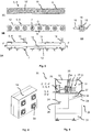
- Figure 1 shows the drive system 1 with two servomotors 2, 2 'in the exemplary game, which drive roller modules 5, 5', 6, 6 'via a motor gear 3, 3' and a coupling 4, 4 '.
- the upper roller modules 5, 5 ' are driven by the motor 2 and the lower roller modules 6, 6' are driven by the motor 2 '.
- the upper roller module 5 ' is shown removed from its operating position in this illustration.
- the role modules 5, 5 ', 6, 6' are further explained below in connection with the Figures 2 and 3 explained.
- the roller modules 5, 5 ', 6, 6' have an elongated housing 8 in which the in Figure 3 drive means shown are housed.
- the longitudinal housing side 13 on the drive side has non-visible openings from which, in this exemplary embodiment, the transmission input shaft 15 protrude for attachment to the clutch 4, 4 '.
- the housing 8 has transmission output shafts 7 which can be non-positively connected via intermediate pieces (not shown) in the usual manner to the corresponding roll forming tools, which are also not shown.
- a connecting shaft 16 protrudes from the housing 8 and is arranged as an extension of the corresponding transmission output shaft 7.
- the connecting shaft 16 can also be the transmission output shaft 7 at the same time.
- the connecting shaft 16 is used to couple a module connecting element 9, 9 'in order to drive the upper roller modules 5, 5' or the lower roller modules 6, 6 'to one another in this way.
- the connecting shaft 16 protrudes from the housing 8 and is inserted into a corresponding opening 29 in the respective module connecting element 9, 9 ′.
- the connecting shaft 16 is arranged in the module connecting element 9, 9 ′.
- the upper roller modules 5, 5 ' are firmly connected to the lower roller modules 6, 6' by means of screw connections via connecting pins 10, which are provided through openings 11 in the housings 8 of the roller modules 5, 5 ', 6, 6'.
- FIG. 2 shows the roller modules 5, 5 ', 6, 6' already explained above and the module connecting elements 9, 9 '.
- the figures show the housing 8 with the housing tops 14 and the openings 11 for the connecting pins 10, which can be pushed through the housing 8.
- the transmission input shaft 15 protruding from the housing 8 and the connecting shaft 16 in the upper roller module 5 and the lower roller module 6 can be seen.
- the upper roller module 5 'and the lower roller module 6' only have the connecting shaft 16 for coupling to the corresponding driven upper roller module 5 or lower roller module 6.
- there are thus two different roller modules the upper roller module with the lower roller module 6 or the upper roller module 5 'with the lower roller module 6' being easily exchanged.
- the roller modules 5, 5 ', 6, 6' are basically constructed in the same way, and are either closed by closing the respective opening provided in the longitudinal side 13 of the housing or by inserting gear input shafts 15 or connecting shaft 16 with regard to the use of the respective roller module 5, 5 ' , 6, 6 'set.
- the module connecting elements 9, 9 ' have gear wheels (not shown) inside for transmitting the drive forces between the upper roller modules 5, 5' and lower roller modules 6, 6 '.
- FIG 3 shows in the Figures 3A to 3D the elements already described above again in detail a roller module 5, 6 (in this exemplary embodiment) as it can, however, also be used for the roller modules 5 ', 6'.
- the transmission output shafts 7 are rotated by means of gear wheels 18 arranged next to one another in the housing 8 and arranged on the transmission output shafts 7, only one gear wheel 18 ′ being driven via the transmission input shaft 15 becomes.
- spacing elements not shown
- the drive system in Figure 1 uses two motors 2, 2 '. In principle, it is also possible to operate the drive system with just one drive motor, with the arrangement as in Figure 1 or in Figure 2 shown, on the connecting shafts 16 an in Figure 4
- the module connection unit 19 shown with four openings 30 with a connecting gear arranged therein is attached, so that the drive in this embodiment according to FIG Figure 1 takes place only with the motor 2 via the top roller module 5 for all other roller modules 5, 6, 6 '. If only one upper roller module 5 and one lower roller module 6 or one lower roller module 6 ′ is used in a drive with the motor 2, a module connection element 9, 9 ′ can be used instead of the module connection unit 19.
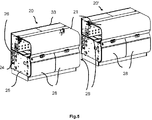
- FIG. 5 shows, in perspective, two profiling modules 20, 20 ', in which such a drive system as shown in FIGS Figures 1 to 4 is shown, is integrated and which have the same structure.
- Each profiling module 20, 20 ' can be seen to have a cover hood 21 via which the transmission output shafts for coupling the schematically illustrated roll forming tools 17 and the area in which the forming takes place are accessible.
- the covering hood 21 serves to cover a work / production area 22 and is articulated to a housing 33 surrounding the drive area 23.
- the drive area 23, in which the motors 2, 2 ', motor gears 3, 3' and clutch 4, 4 'and the drive system 1 are accommodated, is arranged behind it as seen from the operator's side.
- the roller modules 5, 5 'and 6, 6' are located in the drive area 23 and the roller forming tools 17 that can be connected to the roller modules are located in the work / production area 22 and are passed through the partition 35 via intermediate pieces 34 from the gear output shafts 7 of the roller modules 5, 5 'or 6, 6' driven.
- the profiling module 20 also has a supply area 24 below the work / production area 22 and the drive area 23 for laying cables with structured duct systems for separate laying of lines and hoses. In front of it there is a storage area 25 for additional accessories such as, for example, lubricant devices in the form of a lubricant pan 27, a computer system for recording measurement data, etc. Underneath there is an installation and transport area 31.
- a drawer 28 and also a folding compartment 32 are provided as a tool storage area in this area.
- the profiling modules 20, which are independent operational units, can be connected to a system control (not shown) and selected via a program, can be connected to other profiling modules 20 on both sides and inserted into the profiling system or easily removed from it.
Description
- Die vorliegende Erfindung betrifft ein Antriebssystem für ein Profilieranlage zum Längsformen eines Metallbandes oder eines Ausgangsprofils in ein Profil oder Rohr mittels einer Mehrzahl von Rollenumformwerkzeugen in Form von Oberrollen und Unterrollen, wobei die Oberrollen gemeinsam angetrieben sind und die Unterrollen gemeinsam angetrieben sind. Die Erfindung betrifft außerdem ein Profiliermodul mit einem derartigen Antriebssystem.
- Aus der
US 4 831 857 A ist ein derartiges Antriebssystem für Profilieranlagen bekannt, wobei in einem länglichen quaderförmigen Gehäuse Antriebsmittel für einen gemeinsamen Antrieb der Oberrollen bzw. Unterrollen angeordnet sind und das auf der den Oberrollen bzw. Unterrollen gegenüberliegenden Gehäuselängsseite eine Getriebeeingangswelle aufweist, und die Antriebsmittel über eine Kupplung über ein gemeinsames Getriebe mit einem Antriebsmotor antreibbar sind. Die Spindeln der Oberrollen und Unterrollen greifen dabei direkt in die Antriebsmittel als Abgangswelle ein. Diese Art von Antriebssystemen werden je nach Länge und Art der Verformungen der zu verformenden Gegenstände in unterschiedlicher Länge ausgebildet. In der Regel werden die jeweils gemeinsam angetriebenen Oberrollen und Unterrollen über einen Motor und ein gemeinsames Getriebe angetrieben, so dass sich bei einer Veränderung des Profils aufwändige Anpassungen ergeben. Darüber hinaus sind derartige Anlagen nicht einfach in der Länge erweiterbar oder verkürzbar. - Der vorliegenden Erfindung liegt daher die Aufgabe zugrunde, ein Antriebssystem vorzuschlagen, das für eine Profilieranlage geeignet ist und insbesondere in einem Profiliermodul integrierbar und je nach Wunsch des Benutzers auf einfache Weise hinsichtlich der Länge oder des Antriebs variierbar ist, wobei durch die Integration in ein Profiliermodul eine Profilieranlage mit beliebiger Länge je nach Wahl erstellbar ist.
- Diese Aufgabe wird erfindungsgemäß durch ein Antriebssystem mit den Merkmalen des Anspruchs 1 sowie ein Anlagenmodul mit den Merkmalen des Anspruchs 6 gelöst. Weitere vorteilhafte Ausgestaltungen sind den jeweiligen rückbezogenen Unteransprüchen zu entnehmen.
- Danach weist das Antriebssystem Getriebeabgangswellen für Oberrollen und Unterrollen auf, die jeweils in einem Oberrollenmodul bzw. einem Unterrollenmodul mit einem länglichen quaderförmigen Gehäuse gelagert sind. In dem jeweiligen Rollenmodul, mit dem nachfolgend das Oberrollenmodul und das Unterrollenmodul gemeinsam bezeichnet werden, befinden sich Antriebsmittel für einen gemeinsamen Antrieb der in dem Rollenmodul gelagerten Getriebeabgangswellen für die Rollenumformwerkzeuge. Die Antriebsmittel in dem quaderförmigen Gehäuse können dabei auf verschiedene Art und Weise, beispielsweise über eine Antriebswelle mit Zahnrädern für den Antrieb der einzelnen Getriebeabgangswellen fürdie Rollen umformwerkzeuge oder auch bevorzugt über eine Kette von Zahnrädern direkt auf den Getriebeabgangswellen für die Rollenumformwerkzeuge ausgebildet sein. Die Rollenmodule weisen damit auf einer Längsseite des quaderförmigen Gehäuses aus dem Gehäuse herausragende Getriebeabgangswellen und auf der gegenüberliegenden Seite Öffnungen für mindestens eine Getriebeeingangswelle auf. Diese Getriebeeingangswelle kann bereits fest in dem Gehäuse integriert sein und aus dem Gehäuse herausragen oder auch beim Anschluss des motorischen Antriebs in die entsprechende Öffnung eingesteckt werden. Die Rollenmodule sind jeweils als Einheit übereinander anordenbar und lösbar verbindbar und können aufeinander (Oberrollenmodul und Unterrollenmodul) und nebeneinander (Unterrollenmodul neben Unterrollenmodul bzw. Oberrollenmodul neben Oberrollenmodul) angeordnet werden. Über entsprechende Kupplungen, die außen entweder auf die Getriebeeingangswelle aufgesteckt oder eine eigenständige Getriebeeingangswelle aufweisend in die Öffnung des Gehäuses eingesteckt werden, kann der Antrieb eines oder mehrerer Oberrollenmodule getrennt vom Antrieb eines oder mehrerer Unterrollenmodule realisiert werden. Damit ist es möglich, je nach Anforderung auf einfache Weise die Antriebseinheit zu konfigurieren und mit nur einem Antrieb oder mit getrenntem Antrieb für die Oberrollen bzw. die Unterrollen zu versehen, was die Möglichkeit einräumt, die Rollenformwerkzeuge optimal aufeinander abzustimmen.
- Gemäß einer bevorzugten Ausbildungsform können die jeweiligen Rollenmodule, d.h. alle Oberrollenmodule und alle Unterrollenmodule, mit je einem außerhalb des jeweiligen Rollenmoduls anordenbaren Modulverbindungselement verbunden werden. Dies können mehr als zwei Rollenmodule sein. Damit können in einer Profilieranlage oder bevorzugt nur in einem Profiliermodul je nach Anwendungsfall und Wunsch des Benutzers mit unterschiedlich langen Rollenmodulen oder unterschiedlichen Rollenmodulen mit unterschiedlichen Abständen für die Rollenumformwerkzeuge ausgestattet werden. Hierzu weisen die Rollenmodule Verbindungswellen auf, die aus dem Gehäuse herausragen oder im Modulverbindungselement enthalten sind und in dafür vorgesehene Öffnungen im Gehäuse eingesteckt werden. So können beispielsweise in einem Profiliermodul Rollenmodule vorgesehen sein, die ungefähr der Hälfte der Breite des Profiliermoduls entsprechen, so dass das Profiliermodul entweder mit nur einem Oberrollenmodul und einem Unterrollenmodul oder mit zwei Oberrollenmodulen und zwei Unterrollenmodulen betrieben werden kann. Generell ist es auch möglich, mehr als zwei Rollenmodule übereinander anzuordnen. Durch das Modulverbindungselement und die Verbindungswellen kann somit auf einfache Weise ein weiteres Rollenmodul durch das auf einer Ebene liegende Oberrollenmodul bzw. Unterrollenmodul antriebsmäßig verbunden werden. In dem Modulverbindungselement befinden sich ein entsprechend ausgestattetes Getriebe. Durch Einbringung von Abstandselementen kann der Abstand zwischen den Getriebeabgangswellen für die Oberrollen zu den Getriebeabgangswellen für die Unterrollen variabel angepasst werden.
- Bei dem vorstehend beschriebenen Verbindungselement erfolgt die Verbindung von Oberrollenmodul zu Oberrollenmodul bzw. Unterrollenmodul zu Unterrollenmodul. Mit seiner bevorzugten Ausbildung kann durch eine entsprechend ausgestaltete außerhalb des jeweiligen Gehäuses des Rollenmoduls anordenbare Modulverbindungseinheit ein Oberrollenmodul mit einem Unterrollenmodul antriebsseitig verbunden werden. Dies erfolgt ebenfalls derart, dass es von außen, entweder mit entsprechenden Verbindungswellenwellen versehen in die Öffnung des Modulgehäuse einsteckbar ist oder umgekehrt auf aus den Öffnungen herausragenden Verbindungswellen aufsteckbar ist. Eine derartige Modulverbindungseinheit ist dann erforderlich, wenn die Oberrollenmodule und die Unterrollenmodule mit nur einer Antriebseinheit und nicht getrennt voneinander angetrieben werden sollen. Bei der Verwendung von nur einem Oberrollenmodul und einem Unterrollenmodul kann das Modulverbindungselement als Modulverbindungseinheit eingesetzt werden. Auch dieser Aufbau ermöglicht die einfache Konfigurierbarkeit des Antriebssystems entsprechend den Wünschen des Benutzers.
- Grundsätzlich sind mit dieser Ausgestaltung nur zwei verschiedene Rollenmodule erforderlich, wobei das Oberrollenmodul mit der Getriebeeingangswelle auch als Unterrollenmodul und das Oberrollenmodul ohne Getriebeeingangswelle auch als Unterrollenmodul verwendet werden kann. Gemäß einer besonders bevorzugten Ausgestaltung sind die einzelnen Rollenmodule identisch ausgebildet, so dass ein Oberrollenmodul ohne weiteres als Unterrollenmodul betrieben werden kann und umgekehrt. Hierzu enthält jedes Rollenmodul mindestes eine Öffnung, um eine Getriebeeingangswelle einzustecken oder weist bereits eine Getriebeeingangswelle auf. Alle Rollenmodule sind somit baugleich ausgestaltet und unterscheiden sich nur dadurch, dass die entsprechende Öffnung im Gehäuse auf der dem Antrieb zugewandten Seite entweder verschlossen ist oder Getriebeeingangswellen aufweisen. Genauso verhält es sich mit Verbindungswellen zwischen den Rollenmodulen. Dies vereinfacht erheblich die Herstellung und reduziert die Kosten für eine derartige Anlage.
- Zweckmäßigerweise sind die Rollenmodule über Steckverbindungen miteinander verbindbar und aneinander fixierbar. Dies kann beispielsweise durch in dem Gehäuse vorgesehenen und auf der Oberseite und Unterseite angeordneten Öffnungen erfolgen, durch die Verbindungsstangen durchsteckbar sind, mittels denen die Rollenmodule über entsprechende an den Verbindungsstangen vorgesehene Gewinde verschraubbar sind.
- Diese erfindungsgemäße Profiliermodul für eine Profilieranlage zeichnet sich durch ein vorstehend beschriebenes Antriebssystem aus und ist angepasst, durch aneinanderreihen einer Mehrzahl derartiger Profiliermodule eine je nach Anwendungsfall insbesondere in der Länge aber auch bezüglich der Rollenumformwerkzeuge anpassbare Profilieranlage realisieren zu können.
- Gemäß einer besonders bevorzugten Ausgestaltung befinden sich in einem Profiliermodul zwei in einer Ebene angeordnete Oberrollenmodule und zwei in einer Ebene unterhalb der Oberrollenmodule angeordnete Unterrollenmodule, die jeweils mit einem Modulverbindungselement für die Antriebsverbindung der beiden Oberrollenmodule und der beiden Unterrollenmodule versehen sind. Damit kann zum einen eine Rollenmodulgröße realisiert werden, die für ein Profiliermodul geeignet ist, das mit einem üblichen LKW transportiert werden kann. Zum anderen erlaubt die Verwendung von jeweils zwei Rollenmodulen auch bei Bedarf die Entfernung von einem Oberrollenmodul und einem Unterrollenmodul, wenn eine Verkürzung oder eine Änderung der Rollenumformwerkzeugabstände notwendig ist. Zudem kann durch die dadurch entstehende Rollenmodulgröße ein Baukastensystem für eine beliebige Anzahl von Profiliermodulen bereitgestellt werden.
- In einer bevorzugten Ausbildung des Profiliermoduls sind die Oberrollenmodule und die Unterrollenmodule mit Hilfe von Abstandeinheiten erhöhbar und somit der vertikale Abstand der Getriebeabgangswellen zwischen Oberrollenmodul und Unterrollenmodul zueinander individuell vergrößert werden kann.
- Vorteilhafterweise sind bei dem Profiliermodul die Oberrollenmodule und die Unterrollenmodule getrennt voneinander motorisch angetrieben und steuerbar, so dass damit optimal auf die Bedürfnisse des profilierenden Materials eingegangen werden kann.
- Mit der Erfindung ist es somit möglich, ein modular aufgebautes Antriebssystem sowie eine modular aufgebaute Profilieranlage aus entsprechend ausgestalteten Profiliermodulen zur Verfügung zu stellen, die eine Anpassung an die Bedürfnisse des Benutzers auf eine einfache und kostengünstige Art und Weise ermöglicht. Die vorstehend in der Beschreibung genannten Merkmale und Merkmalskombinationen sowie nachfolgend in der Figurenbeschreibung genannten und/oder in den Figuren alleine gezeigten Merkmale und Merkmalskombinationen sind nicht nur in der jeweils angegebenen Kombination, sondern auch in anderen Kombinationen oder in Alleinstellungen verwendbar. Zur Ausführung der Erfindung müssen nicht alle Merkmale des Anspruchs 1 bzw. des Anspruchs 6 verwirklicht sein. Auch können Einzelmerkmale der unabhängigen oder nebengeordneten Ansprüche durch andere offenbarte Merkmale oder Merkmalskombinationen ersetzt werden. Sämtliche aus den Ansprüchen, der Beschreibung oder der Zeichnung hervorgehende Merkmale und/oder Vorteile einschließlich konstruktiver Einzelheiten, räumlich Anordnungen und Verfahrensschritte können sowohl für sich als auch in verschiedenen Kombinationen erfindungswesentlich sein. In den Figuren werden gleiche oder ähnliche Bauteile mit gleichen oder ähnlichen Bezugszeichen gekennzeichnet. Es stellen dar:
- Figur 1
- die perspektivische Ansicht eines Antriebssystems;
- Figur 2
- die perspektivische Ansicht der Rollenmodule mit Modulverbindungselementen;
- Figur 3
- ein Rollenmodul in der Draufsicht (
Figur 3A ), in einer Seitenansicht mit Blick auf die Getriebeabgangswellen für die Rollenumformwerkzeuge (Figur 3B ), eine Schnittdarstellung im Längsschnitt entlang der Linie F-F vonFigur 3A (Figur 3C ) und eine Querschnittsdarstellung entlang der Linie G-G vonFigur 3B (Figur 3D ); - Figur 4
- die in Relation zu
Figur 2 stark vergrößerte perspektivische Ansicht einer Modulverbindungseinheit; - Figur 5
- die perspektivische Ansicht von zwei Profilanlagenmodulen; und
- Figur 6
- die schematische Querschnittdarstellung eines Profiliermoduls.
-
Figur 1 zeigt das Antriebssystem 1 mit in dem Ausführungsspiel zwei Servomotoren 2, 2' die über ein Motorgetriebe 3, 3' und einer Kupplung 4, 4' Rollenmodule 5, 5', 6, 6' antreiben. In dieser Anordnung werden die Oberrollenmodule 5, 5' von dem Motor 2 und die Unterrollenmodule 6, 6' von dem Motor 2' angetrieben. Zur Veranschaulichung ist in dieser Darstellung das Oberrollenmodul 5' aus seiner Betriebsposition entfernt dargestellt. Die Rollenmodule 5, 5', 6, 6' werden nachfolgend noch weiter im Zusammenhang mit denFiguren 2 und3 erläutert. Die Rollenmodule 5, 5', 6, 6' weisen ein längliches Gehäuse 8 auf, in dem die inFigur 3 gezeigten Antriebsmittel untergebracht sind. Die antriebsseitige Gehäuselängsseite 13 weist nicht sichtbare Öffnungen auf, aus denen in diesem Ausführungsbeispiel die Getriebeeingangswelle 15 zum Aufstecken auf die Kupplung 4, 4' herausragen. Des Weiteren weist das Gehäuse 8 auf der gegenüberliegenden Gehäuselängsseite 12 Getriebeabgangswellen 7 auf, die über nicht dargestellte Zwischenstücke in üblicher Art und Weise mit den ebenfalls nicht dargestellten entsprechenden Rollenumformwerkzeugen kraftschlüssig verbindbar sind. Im Bereich eines stirnseitigen Endes des Gehäuses 8 ragt aus dem Gehäuse 8 eine Verbindungswelle 16 heraus, die in Verlängerung der entsprechenden Getriebeabgangswelle 7 angeordnet ist. Die Verbindungswelle 16 kann dabei auch gleichzeitig die Getriebeabgangswelle 7 sein. Die Verbindungswelle 16 dient zur Kupplung eines Modulverbindungselements 9, 9', um die Oberrollenmodule 5, 5' bzw. die Unterrollenmodule 6, 6 'auf diese Art und Weise antriebsmäßig miteinander zu verbinden. In dem Ausführungsbeispiel ragt die Verbindungswelle 16 aus dem Gehäuse 8 heraus und wird in eine entsprechende Öffnung 29 in dem jeweiligen Modulverbindungselement 9, 9' eingesteckt. Genauso gut kann es jedoch auch umgekehrt sein, so dass die Verbindungswelle 16 in dem Modulverbindungselement 9, 9' angeordnet ist. Wie ausFigur 1 weiter ersichtlich, werden die Oberrollenmodule 5, 5' über Verbindungsstifte 10, die durch Öffnungen 11 in den Gehäusen 8 der Rollenmodule 5, 5', 6, 6' vorgesehen sind, mit den Unterrollenmodulen 6, 6' miteinanderfest über Schraubverbindungen verbunden. -
Figur 2 zeigt die vorstehend bereits erläuterten Rollenmodule 5, 5', 6, 6' sowie die Modulverbindungselemente 9, 9'. Die Figuren zeigen die Gehäuse 8 mit den Gehäuseoberseiten 14 und den Öffnungen 11 für die Verbindungsstifte 10, die durch die Gehäuse 8 durchgesteckt werden können. Des Weiteren ersichtlich ist die aus dem Gehäuse 8 herausragende Getriebeeingangswelle 15 und die Verbindungswelle 16 bei dem Oberrollenmodul 5 und dem Unterrollenmodul 6. Das Oberrollenmodul 5' und das Unterrollenmodul 6' weisen in diesem Ausführungsbeispiel nur die Verbindungswelle 16 zum Ankuppeln an das entsprechende angetriebene Oberrollenmodul 5 bzw. Unterrollenmodul 6 auf. Bei dieser Ausführungsform gibt es somit zwei unterschiedliche Rollenmodule, wobei ohne weiteres das Oberrollenmodul mit dem Unterrollenmodul 6 bzw. das Oberrollenmodul 5' mit dem Unterrollenmodul 6' ausgetauscht werden kann. Dies ermöglicht eine hohe Flexibilität bei der Herstellung einer derartigen Anlage. Die Rollenmodule 5, 5', 6, 6' sind grundsätzlich vollständig baugleich aufgebaut, und werden entweder durch Verschließen der in der Gehäuselängsseite 13 vorgesehenen jeweiligen Öffnung oder durch Einstecken von Getriebeeingangswellen 15 bzw. Verbindungswelle 16 hinsichtlich der Verwendung des jeweiligen Rollenmoduls 5, 5', 6, 6' festgelegt. Die Modulverbindungselemente 9, 9' weisen im Inneren nicht dargestellte Zahnräder zur Übertragung der Antriebskräfte zwischen den Oberrollenmodulen 5, 5' bzw. Unterrollenmodulen 6, 6'. -
Figur 3 zeigt in denFiguren 3A bis 3D die bereits vorstehend beschriebenen Elemente noch einmal im Detail ein Rollenmodul 5, 6 (in diesem Ausführungsbeispiel) wie es jedoch auch für die Rollenmodule 5', 6' verwendet werden kann. Die Getriebeabgangswellen 7 werden über in dem Gehäuse 8 nebeneinander angeordnete auf den Getriebeabgangswellen 7 angeordnete Zahnräder 18 gedreht, wobei nur ein Zahnrad 18' über die Getriebeeingangswelle 15 angetrieben wird. Durch Einbringung von nicht dargestellten Abstandselementen zwischen den Oberrollenmodulen 5, 5' und Unterrollenmodulen 6, 6' kann der Abstand zwischen den Getriebeabgangswellen 15 für die Oberrollen zu den Getriebeabgangswellen 15 für die Unterrollen variabel angepasst werden. - Das Antriebssystem in
Figur 1 verwendet zwei Motoren 2, 2'. Grundsätzlich ist es auch möglich, das Antriebssystem mir nur einem Antriebsmotor zu betreiben, wobei bei der Anordnung wie inFigur 1 oder inFigur 2 dargestellt, auf die Verbindungswellen 16 eine inFigur 4 gezeigte Modulverbindungseinheit 19 mit vier Öffnungen 30 mit einem darin angeordneten Verbindungsgetriebe aufgesteckt wird, so dass der Antrieb in diesem Ausführungsbeispiel gemäßFigur 1 nur mit dem Motor 2 über das Oberrollenmodul 5 für alle anderen Rollenmodule 5, 6, 6' erfolgt. Sofern nur ein Oberrollenmodul 5 und ein Unterrollenmodul 6 oder ein Unterrollenmodul 6' bei einem Antrieb mit dem Motor 2 verwendet wird, kann ein Modulverbindungselement 9, 9' statt der Modulverbindungseinheit 19 verwendet werden. -
Figur 5 zeigt perspektivisch zwei Profiliermodule 20, 20', in deren ein derartiges Antriebssystem, wie es in denFiguren 1 bis 4 dargestellt ist, integriert ist und die gleich aufgebaut sind. Wie ausFigur 6 ersichtlich weist jedes Profiliermodul 20, 20' eine Abdeckhaube 21 auf, über die die Getriebeabgangswellen zum Ankuppeln von schematisch dargestellten Rollenformwerkzeugen 17 und der Bereich in dem die Umformung stattfindet, zugänglich sind. Die Abdeckhaube 21 dient der Abdeckung eines Arbeits-/Produktionsbereiches 22 und ist an ein den Antriebsbereich 23 umschließendes Gehäuse 33 angelenkt. Von der Bedienerseite gesehen dahinter angeordnet, ist der Antriebsbereich 23, in dem die Motoren 2, 2', Motorgetriebe 3, 3' und Kupplung 4, 4' sowie das Antriebssystem 1 untergebracht. Die Rollenmodule 5, 5' bzw. 6, 6' befinden sich in dem Antriebsbereich 23 und die an die Rollenmodule anschließbaren Rollenumformwerkzeuge 17 befinden sich im Arbeits-/Produktionsbereich 22 und werden durch die Trennwand 35 hindurch über Zwischenstücke 34 von den Getriebeabgangswellen 7 der Rollenmodule 5, 5' bzw. 6, 6'angetrieben. Das Profiliermodul 20 weist außerdem unter dem Arbeits-/Produktionsbereich 22 und dem Antriebsbereich 23 einen Versorgungsbereich 24 für die Verlegung von Kabeln mit strukturierten Kanalsystemen für getrennte Leitungsverlegung und Schläuche. Davor befindet sich ein Staubereich 25 für zusätzliches Zubehör wie z.B. Schmiermitteleinrichtungen in Form einer Schmiermittelwanne 27, Rechnersystem für Messdatenerfassung usw. auf. Darunter befindet sich ein Aufstell- und Transportbereich 31. Bei dem Ausführungsbeispiel ist in diesem Bereich eine Schublade 28 und auch noch eine Klappfach 32 als Werkzeugablage vorgesehen. An der Stirnseite 26 können die Profiliermodule 20, die selbstständige betriebsfähige Einheiten sind, an eine nicht dargestellte Systemsteuerung anschließbar und über ein Programm auswählbar sind, beidseitig mit anderen Profiliermodulen 20 verbunden werden und in die Profilieranlage eingefügt oder ohne weiteres aus dieser entnommen werden.
Claims (9)
- Antriebssystem (1) für eine Profilieranlage zum Längsformen eines Metallbandes oder eines Ausgangsprofils in ein Profil oder Rohr mittels einer Mehrzahl von Rollenumformwerkzeugen (17) in Form von Oberrollen und Unterrollen, wobei die Oberrollen gemeinsam angetrieben sind und die Unterrollen gemeinsam angetrieben sind, wobei mindestens ein Oberrollenmodul (5, 5') und mindestens ein Unterrollenmodul (6, 6') mit einem länglichen quaderförmigen Gehäuse (8) mit darin befindlichen Antriebsmittel (18) für einen gemeinsamen Antrieb der Oberrollen bzw. Unterrollen durch Getriebeabgangswellen (7, 7') für die Oberrollen bzw. die Unterrollen, die jeweils in dem mindestens einen Oberrollenmodul (5, 5') und dem mindestens einen Unterrollenmodul (6, 6') gelagert sind und aus einer Gehäuselängsseite (12) herausragen, und das auf der den Oberrollen bzw. Unterrollen gegenüberliegenden Gehäuselängsseite (13) eine Getriebeeingangswelle (15) aufweist, wobei das mindestens eine Oberrollenmodul (5, 5') und das mindestens eine Unterrollenmodul (6, 6') jeweils als Einheit übereinander anordenbar und lösbar verbindbar sind und die Getriebeabgangswellen (7, 7') für die Oberrollen und die Unterrollen über eine Kupplung (4) über ein gemeinsames Getriebe (3) mit einem Antriebsmotor (2) oder getrennt voneinander mit jeweils zugeordnetem Kupplung (4, 4'), Getriebe (3, 3') und Antriebsmotor (2, 2') antreibbar sind.
- Antriebssystem (1) nach Anspruch 1, gekennzeichnet durch ein außerhalb des jeweiligen Rollenmoduls (5, 5'; 6, 6') anordenbares Modulverbindungselement (9, 9') mit dem die jeweiligen Getriebeabgangswellen (7') eines ersten Oberrollenmoduls (5) bzw. Unterrollenmoduls (6) antriebsseitig mit den Getriebeabgangswellen (7') eines weiteren Oberrollenmoduls (5') bzw. Unterrollenmoduls (6') verbindbar sind.
- Antriebssystem (1) nach Anspruch 1 oder Anspruch 2, gekennzeichnet durch eine außerhalb des jeweiligen Rollenmoduls (5, 5'; 6, 6') anordenbare Modulverbindungseinheit (19) mit der mindestens ein Oberrollenmodul (5, 5') mit einem Unterrollenmodul (6, 6') antriebsseitig verbindbar ist.
- Antriebssystem (1) nach einem der vorangegangenen Ansprüche, dadurch gekennzeichnet, dass das mindestens eine Oberrollenmodul (5, 5') und das mindestens eine Unterrollenmodul (6, 6') vom Aufbau und dem Gehäuse (8) identisch aufgebaut sind.
- Antriebssystem (1) nach einem der vorangegangenen Ansprüche, dadurch gekennzeichnet, dass das mindestens eine Oberrollenmodul (5, 5') und das mindestens eine Unterrollenmodul (6, 6') über Steckverbindungen (10) miteinander verbindbar und aneinander fixierbar sind.
- Profiliermodul (20) für eine Profilieranlage zum Längsformen eines Metallbandes oder eines Ausgangsprofil in ein Profil oder Rohr mittels einer Mehrzahl von Rollenumformwerkzeugen (17) in Form von Oberrollen und Unterrollen, wobei die Oberrollen gemeinsam angetrieben sind und die Unterrollen gemeinsam angetrieben sind, gekennzeichnet durch ein Antriebssystem (1) nach einem der vorangegangenen Ansprüche.
- Profiliermodul (20) nach Anspruch 6, dadurch gekennzeichnet, dass zwei in einer Ebene angeordnete Oberrollenmodule (5, 5') und zwei in einer Ebene unterhalb der Oberrollenmodule (5, 5') angeordnete Unterrollenmodule (6, 6'), die jeweils mit einem Modulverbindungselement (9, 9') für die Antriebsverbindung der beiden Oberrollenmodule (5, 5') und der beiden Unterrollenmodule (6, 6') versehen sind.
- Profiliermodul (20) nach Anspruch 7, dadurch gekennzeichnet, dass die Oberrollenmodule (5, 5') und die Unterrollenmodule (6, 6') getrennt voneinander motorisch angetrieben und steuerbar sind.
- Profiliermodul (20) nach einem der vorangegangenen Ansprüche 6 bis 8, dadurch gekennzeichnet, dass die Oberrollenmodule (5, 5') und die Unterrollenmodule (6, 6') mit Hilfe von Abstandeinheiten erhöhbar sind.
Priority Applications (1)
| Application Number | Priority Date | Filing Date | Title |
|---|---|---|---|
| PL19783032T PL3672741T3 (pl) | 2018-10-22 | 2019-10-08 | Układ napędowy i moduł profilujący do instalacji profilującej |
Applications Claiming Priority (2)
| Application Number | Priority Date | Filing Date | Title |
|---|---|---|---|
| EP18201776.4A EP3643420A1 (de) | 2018-10-22 | 2018-10-22 | Antriebssystem und profilieranlagenmodul für eine profilieranlage |
| PCT/EP2019/077173 WO2020083635A1 (de) | 2018-10-22 | 2019-10-08 | Antriebssystem und profiliermodul für eine profilieranlage |
Publications (2)
| Publication Number | Publication Date |
|---|---|
| EP3672741A1 EP3672741A1 (de) | 2020-07-01 |
| EP3672741B1 true EP3672741B1 (de) | 2021-05-05 |
Family
ID=63965257
Family Applications (2)
| Application Number | Title | Priority Date | Filing Date |
|---|---|---|---|
| EP18201776.4A Withdrawn EP3643420A1 (de) | 2018-10-22 | 2018-10-22 | Antriebssystem und profilieranlagenmodul für eine profilieranlage |
| EP19783032.6A Active EP3672741B1 (de) | 2018-10-22 | 2019-10-08 | Antriebssystem und profiliermodul für eine profilieranlage |
Family Applications Before (1)
| Application Number | Title | Priority Date | Filing Date |
|---|---|---|---|
| EP18201776.4A Withdrawn EP3643420A1 (de) | 2018-10-22 | 2018-10-22 | Antriebssystem und profilieranlagenmodul für eine profilieranlage |
Country Status (4)
| Country | Link |
|---|---|
| EP (2) | EP3643420A1 (de) |
| ES (1) | ES2887955T3 (de) |
| PL (1) | PL3672741T3 (de) |
| WO (1) | WO2020083635A1 (de) |
Family Cites Families (4)
| Publication number | Priority date | Publication date | Assignee | Title |
|---|---|---|---|---|
| US4831857A (en) * | 1988-03-18 | 1989-05-23 | Tishken Products Co. | Machine with quick disconnect between spindle drive train and power transmission |
| US6053022A (en) * | 1998-09-14 | 2000-04-25 | Morgan Construction Company | Modular rolling mill |
| AT515177B1 (de) * | 2013-12-10 | 2015-08-15 | Asmag Holding Gmbh | Antriebssystem sowie damit ausgerüstete Profilieranlage |
| CN203695670U (zh) * | 2014-02-20 | 2014-07-09 | 杭州一波机械有限公司 | C/z檩条互换生产线 |
-
2018
- 2018-10-22 EP EP18201776.4A patent/EP3643420A1/de not_active Withdrawn
-
2019
- 2019-10-08 EP EP19783032.6A patent/EP3672741B1/de active Active
- 2019-10-08 WO PCT/EP2019/077173 patent/WO2020083635A1/de unknown
- 2019-10-08 ES ES19783032T patent/ES2887955T3/es active Active
- 2019-10-08 PL PL19783032T patent/PL3672741T3/pl unknown
Also Published As
| Publication number | Publication date |
|---|---|
| WO2020083635A1 (de) | 2020-04-30 |
| EP3643420A1 (de) | 2020-04-29 |
| PL3672741T3 (pl) | 2021-12-13 |
| ES2887955T3 (es) | 2021-12-29 |
| EP3672741A1 (de) | 2020-07-01 |
Similar Documents
| Publication | Publication Date | Title |
|---|---|---|
| DE852326C (de) | Untersetzungsgetriebe | |
| DE69912646T2 (de) | Einstellbare schiene zum fördern von produkten | |
| DE102014205036A1 (de) | Endoskopisches Instrument zum Anschluss an einen Operationsroboter | |
| EP3122520A1 (de) | Roboterarm und montageset | |
| DE3234981C3 (de) | Stanz-Biege-Maschine zum Bearbeiten von Draht oder Band | |
| DE3917036A1 (de) | Luftdurchlassvorrichtung fuer belueftungsoeffnungen | |
| DE3224896C2 (de) | ||
| EP3137354A1 (de) | Betätigungsvorrichtung für eine elektromechanisch betätigbare fahrzeugbremse | |
| EP3918897A1 (de) | Dosiereinrichtung, insbesondere für eine drillmaschine | |
| DE202015105566U1 (de) | Lineares Stellglied | |
| EP3672741B1 (de) | Antriebssystem und profiliermodul für eine profilieranlage | |
| DE2707699B2 (de) | Zahnradgetriebe mit veränderbarer Übersetzung | |
| DE112013004544T5 (de) | Antriebseinheit für Kettenantriebe im Bergbau | |
| DE19835167A1 (de) | Führungsschiene für Geräte zur Beton- bzw. Gesteinsbearbeitung | |
| DE202013103426U1 (de) | Vorrichtung zur Erzeugung einer Bohrung in einem Werkstück oder eines Gewindes in einer Bohrung eines Werkstücks | |
| DE69824888T2 (de) | Fütterungsgitter | |
| EP0211188A1 (de) | Abdeckeinrichtung | |
| EP3643419B1 (de) | Profilieranlage mit profilieranlagenmodul | |
| EP0089074B1 (de) | Anordnung zum Trennen einzelner Leiter voneinander in einem Flachbandkabel | |
| DE20106862U1 (de) | Rotierende Stützstruktur für die Werkzeuge in einer Motorharke und dazugehörige Motorharke | |
| DE19637973B4 (de) | Gewinnungshobel mit höhenverstellbarem Firstmeißelträger | |
| EP3354610B1 (de) | Falzmaschine | |
| DE202017100411U1 (de) | Falzmaschine | |
| DE2623066A1 (de) | Antriebsstation fuer eine foerder- und gewinnungsanlage fuer bergbau-gewinnungsbetriebe | |
| EP2359714A1 (de) | Vorrichtung zur Positionierung eines Schubkastens auf Schubkastenführungen |
Legal Events
| Date | Code | Title | Description |
|---|---|---|---|
| STAA | Information on the status of an ep patent application or granted ep patent |
Free format text: STATUS: UNKNOWN |
|
| STAA | Information on the status of an ep patent application or granted ep patent |
Free format text: STATUS: EXAMINATION IS IN PROGRESS |
|
| PUAI | Public reference made under article 153(3) epc to a published international application that has entered the european phase |
Free format text: ORIGINAL CODE: 0009012 |
|
| 17P | Request for examination filed |
Effective date: 20200227 |
|
| AK | Designated contracting states |
Kind code of ref document: A1 Designated state(s): AL AT BE BG CH CY CZ DE DK EE ES FI FR GB GR HR HU IE IS IT LI LT LU LV MC MK MT NL NO PL PT RO RS SE SI SK SM TR |
|
| AX | Request for extension of the european patent |
Extension state: BA ME |
|
| GRAP | Despatch of communication of intention to grant a patent |
Free format text: ORIGINAL CODE: EPIDOSNIGR1 |
|
| STAA | Information on the status of an ep patent application or granted ep patent |
Free format text: STATUS: GRANT OF PATENT IS INTENDED |
|
| INTG | Intention to grant announced |
Effective date: 20201111 |
|
| GRAS | Grant fee paid |
Free format text: ORIGINAL CODE: EPIDOSNIGR3 |
|
| STAA | Information on the status of an ep patent application or granted ep patent |
Free format text: STATUS: GRANT OF PATENT IS INTENDED |
|
| GRAJ | Information related to disapproval of communication of intention to grant by the applicant or resumption of examination proceedings by the epo deleted |
Free format text: ORIGINAL CODE: EPIDOSDIGR1 |
|
| GRAL | Information related to payment of fee for publishing/printing deleted |
Free format text: ORIGINAL CODE: EPIDOSDIGR3 |
|
| STAA | Information on the status of an ep patent application or granted ep patent |
Free format text: STATUS: EXAMINATION IS IN PROGRESS |
|
| INTC | Intention to grant announced (deleted) | ||
| GRAP | Despatch of communication of intention to grant a patent |
Free format text: ORIGINAL CODE: EPIDOSNIGR1 |
|
| STAA | Information on the status of an ep patent application or granted ep patent |
Free format text: STATUS: GRANT OF PATENT IS INTENDED |
|
| GRAA | (expected) grant |
Free format text: ORIGINAL CODE: 0009210 |
|
| STAA | Information on the status of an ep patent application or granted ep patent |
Free format text: STATUS: THE PATENT HAS BEEN GRANTED |
|
| DAV | Request for validation of the european patent (deleted) | ||
| DAX | Request for extension of the european patent (deleted) | ||
| INTG | Intention to grant announced |
Effective date: 20210317 |
|
| AK | Designated contracting states |
Kind code of ref document: B1 Designated state(s): AL AT BE BG CH CY CZ DE DK EE ES FI FR GB GR HR HU IE IS IT LI LT LU LV MC MK MT NL NO PL PT RO RS SE SI SK SM TR |
|
| REG | Reference to a national code |
Ref country code: GB Ref legal event code: FG4D Free format text: NOT ENGLISH |
|
| REG | Reference to a national code |
Ref country code: CH Ref legal event code: EP |
|
| REG | Reference to a national code |
Ref country code: AT Ref legal event code: REF Ref document number: 1389156 Country of ref document: AT Kind code of ref document: T Effective date: 20210515 |
|
| REG | Reference to a national code |
Ref country code: DE Ref legal event code: R096 Ref document number: 502019001379 Country of ref document: DE |
|
| REG | Reference to a national code |
Ref country code: IE Ref legal event code: FG4D Free format text: LANGUAGE OF EP DOCUMENT: GERMAN |
|
| REG | Reference to a national code |
Ref country code: NL Ref legal event code: FP |
|
| REG | Reference to a national code |
Ref country code: LT Ref legal event code: MG9D |
|
| PG25 | Lapsed in a contracting state [announced via postgrant information from national office to epo] |
Ref country code: FI Free format text: LAPSE BECAUSE OF FAILURE TO SUBMIT A TRANSLATION OF THE DESCRIPTION OR TO PAY THE FEE WITHIN THE PRESCRIBED TIME-LIMIT Effective date: 20210505 Ref country code: HR Free format text: LAPSE BECAUSE OF FAILURE TO SUBMIT A TRANSLATION OF THE DESCRIPTION OR TO PAY THE FEE WITHIN THE PRESCRIBED TIME-LIMIT Effective date: 20210505 Ref country code: LT Free format text: LAPSE BECAUSE OF FAILURE TO SUBMIT A TRANSLATION OF THE DESCRIPTION OR TO PAY THE FEE WITHIN THE PRESCRIBED TIME-LIMIT Effective date: 20210505 Ref country code: BG Free format text: LAPSE BECAUSE OF FAILURE TO SUBMIT A TRANSLATION OF THE DESCRIPTION OR TO PAY THE FEE WITHIN THE PRESCRIBED TIME-LIMIT Effective date: 20210805 |
|
| PG25 | Lapsed in a contracting state [announced via postgrant information from national office to epo] |
Ref country code: GR Free format text: LAPSE BECAUSE OF FAILURE TO SUBMIT A TRANSLATION OF THE DESCRIPTION OR TO PAY THE FEE WITHIN THE PRESCRIBED TIME-LIMIT Effective date: 20210806 Ref country code: IS Free format text: LAPSE BECAUSE OF FAILURE TO SUBMIT A TRANSLATION OF THE DESCRIPTION OR TO PAY THE FEE WITHIN THE PRESCRIBED TIME-LIMIT Effective date: 20210905 Ref country code: RS Free format text: LAPSE BECAUSE OF FAILURE TO SUBMIT A TRANSLATION OF THE DESCRIPTION OR TO PAY THE FEE WITHIN THE PRESCRIBED TIME-LIMIT Effective date: 20210505 Ref country code: PT Free format text: LAPSE BECAUSE OF FAILURE TO SUBMIT A TRANSLATION OF THE DESCRIPTION OR TO PAY THE FEE WITHIN THE PRESCRIBED TIME-LIMIT Effective date: 20210906 Ref country code: SE Free format text: LAPSE BECAUSE OF FAILURE TO SUBMIT A TRANSLATION OF THE DESCRIPTION OR TO PAY THE FEE WITHIN THE PRESCRIBED TIME-LIMIT Effective date: 20210505 Ref country code: LV Free format text: LAPSE BECAUSE OF FAILURE TO SUBMIT A TRANSLATION OF THE DESCRIPTION OR TO PAY THE FEE WITHIN THE PRESCRIBED TIME-LIMIT Effective date: 20210505 Ref country code: NO Free format text: LAPSE BECAUSE OF FAILURE TO SUBMIT A TRANSLATION OF THE DESCRIPTION OR TO PAY THE FEE WITHIN THE PRESCRIBED TIME-LIMIT Effective date: 20210805 |
|
| REG | Reference to a national code |
Ref country code: ES Ref legal event code: FG2A Ref document number: 2887955 Country of ref document: ES Kind code of ref document: T3 Effective date: 20211229 |
|
| PG25 | Lapsed in a contracting state [announced via postgrant information from national office to epo] |
Ref country code: SM Free format text: LAPSE BECAUSE OF FAILURE TO SUBMIT A TRANSLATION OF THE DESCRIPTION OR TO PAY THE FEE WITHIN THE PRESCRIBED TIME-LIMIT Effective date: 20210505 Ref country code: RO Free format text: LAPSE BECAUSE OF FAILURE TO SUBMIT A TRANSLATION OF THE DESCRIPTION OR TO PAY THE FEE WITHIN THE PRESCRIBED TIME-LIMIT Effective date: 20210505 Ref country code: DK Free format text: LAPSE BECAUSE OF FAILURE TO SUBMIT A TRANSLATION OF THE DESCRIPTION OR TO PAY THE FEE WITHIN THE PRESCRIBED TIME-LIMIT Effective date: 20210505 Ref country code: CZ Free format text: LAPSE BECAUSE OF FAILURE TO SUBMIT A TRANSLATION OF THE DESCRIPTION OR TO PAY THE FEE WITHIN THE PRESCRIBED TIME-LIMIT Effective date: 20210505 Ref country code: EE Free format text: LAPSE BECAUSE OF FAILURE TO SUBMIT A TRANSLATION OF THE DESCRIPTION OR TO PAY THE FEE WITHIN THE PRESCRIBED TIME-LIMIT Effective date: 20210505 Ref country code: SK Free format text: LAPSE BECAUSE OF FAILURE TO SUBMIT A TRANSLATION OF THE DESCRIPTION OR TO PAY THE FEE WITHIN THE PRESCRIBED TIME-LIMIT Effective date: 20210505 |
|
| REG | Reference to a national code |
Ref country code: DE Ref legal event code: R082 Ref document number: 502019001379 Country of ref document: DE Representative=s name: WITTE, WELLER & PARTNER PATENTANWAELTE MBB, DE |
|
| REG | Reference to a national code |
Ref country code: DE Ref legal event code: R097 Ref document number: 502019001379 Country of ref document: DE |
|
| PLBE | No opposition filed within time limit |
Free format text: ORIGINAL CODE: 0009261 |
|
| STAA | Information on the status of an ep patent application or granted ep patent |
Free format text: STATUS: NO OPPOSITION FILED WITHIN TIME LIMIT |
|
| 26N | No opposition filed |
Effective date: 20220208 |
|
| PG25 | Lapsed in a contracting state [announced via postgrant information from national office to epo] |
Ref country code: IS Free format text: LAPSE BECAUSE OF FAILURE TO SUBMIT A TRANSLATION OF THE DESCRIPTION OR TO PAY THE FEE WITHIN THE PRESCRIBED TIME-LIMIT Effective date: 20210905 Ref country code: AL Free format text: LAPSE BECAUSE OF FAILURE TO SUBMIT A TRANSLATION OF THE DESCRIPTION OR TO PAY THE FEE WITHIN THE PRESCRIBED TIME-LIMIT Effective date: 20210505 |
|
| PG25 | Lapsed in a contracting state [announced via postgrant information from national office to epo] |
Ref country code: MC Free format text: LAPSE BECAUSE OF FAILURE TO SUBMIT A TRANSLATION OF THE DESCRIPTION OR TO PAY THE FEE WITHIN THE PRESCRIBED TIME-LIMIT Effective date: 20210505 |
|
| PG25 | Lapsed in a contracting state [announced via postgrant information from national office to epo] |
Ref country code: LU Free format text: LAPSE BECAUSE OF NON-PAYMENT OF DUE FEES Effective date: 20211008 |
|
| PG25 | Lapsed in a contracting state [announced via postgrant information from national office to epo] |
Ref country code: FR Free format text: LAPSE BECAUSE OF NON-PAYMENT OF DUE FEES Effective date: 20211031 |
|
| PG25 | Lapsed in a contracting state [announced via postgrant information from national office to epo] |
Ref country code: IE Free format text: LAPSE BECAUSE OF NON-PAYMENT OF DUE FEES Effective date: 20211008 |
|
| PGFP | Annual fee paid to national office [announced via postgrant information from national office to epo] |
Ref country code: BE Payment date: 20221019 Year of fee payment: 4 |
|
| PG25 | Lapsed in a contracting state [announced via postgrant information from national office to epo] |
Ref country code: CY Free format text: LAPSE BECAUSE OF FAILURE TO SUBMIT A TRANSLATION OF THE DESCRIPTION OR TO PAY THE FEE WITHIN THE PRESCRIBED TIME-LIMIT Effective date: 20210505 |
|
| PG25 | Lapsed in a contracting state [announced via postgrant information from national office to epo] |
Ref country code: HU Free format text: LAPSE BECAUSE OF FAILURE TO SUBMIT A TRANSLATION OF THE DESCRIPTION OR TO PAY THE FEE WITHIN THE PRESCRIBED TIME-LIMIT; INVALID AB INITIO Effective date: 20191008 |
|
| PGFP | Annual fee paid to national office [announced via postgrant information from national office to epo] |
Ref country code: PL Payment date: 20230928 Year of fee payment: 5 Ref country code: NL Payment date: 20231019 Year of fee payment: 5 |
|
| PGFP | Annual fee paid to national office [announced via postgrant information from national office to epo] |
Ref country code: ES Payment date: 20231227 Year of fee payment: 5 |
|
| PGFP | Annual fee paid to national office [announced via postgrant information from national office to epo] |
Ref country code: IT Payment date: 20231026 Year of fee payment: 5 Ref country code: DE Payment date: 20231127 Year of fee payment: 5 Ref country code: CH Payment date: 20231102 Year of fee payment: 5 |
|
| PGFP | Annual fee paid to national office [announced via postgrant information from national office to epo] |
Ref country code: BE Payment date: 20231019 Year of fee payment: 5 |