EP0456822B1 - Article moule dans un moule, presentant une surface mate et procede de production - Google Patents
Article moule dans un moule, presentant une surface mate et procede de production Download PDFInfo
- Publication number
- EP0456822B1 EP0456822B1 EP89913243A EP89913243A EP0456822B1 EP 0456822 B1 EP0456822 B1 EP 0456822B1 EP 89913243 A EP89913243 A EP 89913243A EP 89913243 A EP89913243 A EP 89913243A EP 0456822 B1 EP0456822 B1 EP 0456822B1
- Authority
- EP
- European Patent Office
- Prior art keywords
- recesses
- mold
- projections
- matted
- layer
- Prior art date
- Legal status (The legal status is an assumption and is not a legal conclusion. Google has not performed a legal analysis and makes no representation as to the accuracy of the status listed.)
- Expired - Lifetime
Links
- 238000004519 manufacturing process Methods 0.000 title claims abstract description 13
- 238000012546 transfer Methods 0.000 claims abstract description 60
- 230000000694 effects Effects 0.000 claims abstract description 28
- 229920005989 resin Polymers 0.000 claims abstract description 21
- 239000011347 resin Substances 0.000 claims abstract description 21
- 229920003023 plastic Polymers 0.000 claims abstract description 8
- 239000004033 plastic Substances 0.000 claims abstract description 8
- 239000010410 layer Substances 0.000 claims description 68
- 238000000034 method Methods 0.000 claims description 37
- 239000000758 substrate Substances 0.000 claims description 30
- 239000012790 adhesive layer Substances 0.000 claims description 12
- 230000000295 complement effect Effects 0.000 claims description 2
- 230000009977 dual effect Effects 0.000 claims 2
- 230000006378 damage Effects 0.000 abstract description 8
- 239000000463 material Substances 0.000 abstract description 5
- 238000001746 injection moulding Methods 0.000 abstract description 2
- 238000011109 contamination Methods 0.000 abstract 1
- 230000001747 exhibiting effect Effects 0.000 abstract 1
- 238000000465 moulding Methods 0.000 description 17
- 229920001893 acrylonitrile styrene Polymers 0.000 description 6
- 238000013461 design Methods 0.000 description 6
- 239000010408 film Substances 0.000 description 6
- -1 polyethylene terephthalate Polymers 0.000 description 6
- SCUZVMOVTVSBLE-UHFFFAOYSA-N prop-2-enenitrile;styrene Chemical compound C=CC#N.C=CC1=CC=CC=C1 SCUZVMOVTVSBLE-UHFFFAOYSA-N 0.000 description 6
- 239000002985 plastic film Substances 0.000 description 5
- 229920006255 plastic film Polymers 0.000 description 5
- 238000007639 printing Methods 0.000 description 5
- VYPSYNLAJGMNEJ-UHFFFAOYSA-N Silicium dioxide Chemical compound O=[Si]=O VYPSYNLAJGMNEJ-UHFFFAOYSA-N 0.000 description 4
- 230000015572 biosynthetic process Effects 0.000 description 4
- 238000002347 injection Methods 0.000 description 4
- 239000007924 injection Substances 0.000 description 4
- 239000004743 Polypropylene Substances 0.000 description 3
- 238000011068 loading method Methods 0.000 description 3
- 239000003973 paint Substances 0.000 description 3
- 229920001155 polypropylene Polymers 0.000 description 3
- 229920000915 polyvinyl chloride Polymers 0.000 description 3
- 238000012545 processing Methods 0.000 description 3
- 238000007650 screen-printing Methods 0.000 description 3
- XLYOFNOQVPJJNP-UHFFFAOYSA-N water Substances O XLYOFNOQVPJJNP-UHFFFAOYSA-N 0.000 description 3
- 239000004925 Acrylic resin Substances 0.000 description 2
- 229920000178 Acrylic resin Polymers 0.000 description 2
- VTYYLEPIZMXCLO-UHFFFAOYSA-L Calcium carbonate Chemical compound [Ca+2].[O-]C([O-])=O VTYYLEPIZMXCLO-UHFFFAOYSA-L 0.000 description 2
- VVQNEPGJFQJSBK-UHFFFAOYSA-N Methyl methacrylate Chemical compound COC(=O)C(C)=C VVQNEPGJFQJSBK-UHFFFAOYSA-N 0.000 description 2
- PXHVJJICTQNCMI-UHFFFAOYSA-N Nickel Chemical compound [Ni] PXHVJJICTQNCMI-UHFFFAOYSA-N 0.000 description 2
- 239000004698 Polyethylene Substances 0.000 description 2
- 238000003486 chemical etching Methods 0.000 description 2
- 238000000576 coating method Methods 0.000 description 2
- 239000003822 epoxy resin Substances 0.000 description 2
- 238000005530 etching Methods 0.000 description 2
- 238000007646 gravure printing Methods 0.000 description 2
- 230000000704 physical effect Effects 0.000 description 2
- 239000000049 pigment Substances 0.000 description 2
- 229920000647 polyepoxide Polymers 0.000 description 2
- 229920000573 polyethylene Polymers 0.000 description 2
- 229920005749 polyurethane resin Polymers 0.000 description 2
- 239000000843 powder Substances 0.000 description 2
- 239000012260 resinous material Substances 0.000 description 2
- 239000004576 sand Substances 0.000 description 2
- 229920005992 thermoplastic resin Polymers 0.000 description 2
- 229920001187 thermosetting polymer Polymers 0.000 description 2
- 229920000298 Cellophane Polymers 0.000 description 1
- VYZAMTAEIAYCRO-UHFFFAOYSA-N Chromium Chemical compound [Cr] VYZAMTAEIAYCRO-UHFFFAOYSA-N 0.000 description 1
- 239000004640 Melamine resin Substances 0.000 description 1
- 229920000877 Melamine resin Polymers 0.000 description 1
- 239000000654 additive Substances 0.000 description 1
- 229910052782 aluminium Inorganic materials 0.000 description 1
- XAGFODPZIPBFFR-UHFFFAOYSA-N aluminium Chemical compound [Al] XAGFODPZIPBFFR-UHFFFAOYSA-N 0.000 description 1
- 238000000149 argon plasma sintering Methods 0.000 description 1
- 239000011324 bead Substances 0.000 description 1
- 229910000019 calcium carbonate Inorganic materials 0.000 description 1
- 230000015556 catabolic process Effects 0.000 description 1
- 239000011248 coating agent Substances 0.000 description 1
- 239000002131 composite material Substances 0.000 description 1
- 238000007796 conventional method Methods 0.000 description 1
- 238000001816 cooling Methods 0.000 description 1
- 238000006731 degradation reaction Methods 0.000 description 1
- 238000005137 deposition process Methods 0.000 description 1
- 239000005038 ethylene vinyl acetate Substances 0.000 description 1
- 238000001704 evaporation Methods 0.000 description 1
- 239000004744 fabric Substances 0.000 description 1
- 210000004905 finger nail Anatomy 0.000 description 1
- 239000011521 glass Substances 0.000 description 1
- 239000005337 ground glass Substances 0.000 description 1
- 208000015181 infectious disease Diseases 0.000 description 1
- 238000007733 ion plating Methods 0.000 description 1
- 230000001678 irradiating effect Effects 0.000 description 1
- 239000010985 leather Substances 0.000 description 1
- 230000000873 masking effect Effects 0.000 description 1
- 229910052751 metal Inorganic materials 0.000 description 1
- 239000002184 metal Substances 0.000 description 1
- 239000002991 molded plastic Substances 0.000 description 1
- 229910052759 nickel Inorganic materials 0.000 description 1
- 229920006284 nylon film Polymers 0.000 description 1
- 239000000123 paper Substances 0.000 description 1
- 239000002245 particle Substances 0.000 description 1
- 229920001200 poly(ethylene-vinyl acetate) Polymers 0.000 description 1
- 229920000139 polyethylene terephthalate Polymers 0.000 description 1
- 239000005020 polyethylene terephthalate Substances 0.000 description 1
- 239000004800 polyvinyl chloride Substances 0.000 description 1
- 239000011241 protective layer Substances 0.000 description 1
- 230000000717 retained effect Effects 0.000 description 1
- 238000006748 scratching Methods 0.000 description 1
- 230000002393 scratching effect Effects 0.000 description 1
- 210000002374 sebum Anatomy 0.000 description 1
- 239000000377 silicon dioxide Substances 0.000 description 1
- 238000005507 spraying Methods 0.000 description 1
- 238000004544 sputter deposition Methods 0.000 description 1
- 238000010186 staining Methods 0.000 description 1
- 239000010409 thin film Substances 0.000 description 1
- 238000001771 vacuum deposition Methods 0.000 description 1
Images


Classifications
-
- B—PERFORMING OPERATIONS; TRANSPORTING
- B29—WORKING OF PLASTICS; WORKING OF SUBSTANCES IN A PLASTIC STATE IN GENERAL
- B29C—SHAPING OR JOINING OF PLASTICS; SHAPING OF MATERIAL IN A PLASTIC STATE, NOT OTHERWISE PROVIDED FOR; AFTER-TREATMENT OF THE SHAPED PRODUCTS, e.g. REPAIRING
- B29C45/00—Injection moulding, i.e. forcing the required volume of moulding material through a nozzle into a closed mould; Apparatus therefor
- B29C45/14—Injection moulding, i.e. forcing the required volume of moulding material through a nozzle into a closed mould; Apparatus therefor incorporating preformed parts or layers, e.g. injection moulding around inserts or for coating articles
- B29C45/14778—Injection moulding, i.e. forcing the required volume of moulding material through a nozzle into a closed mould; Apparatus therefor incorporating preformed parts or layers, e.g. injection moulding around inserts or for coating articles the article consisting of a material with particular properties, e.g. porous, brittle
- B29C45/14811—Multilayered articles
-
- B—PERFORMING OPERATIONS; TRANSPORTING
- B29—WORKING OF PLASTICS; WORKING OF SUBSTANCES IN A PLASTIC STATE IN GENERAL
- B29C—SHAPING OR JOINING OF PLASTICS; SHAPING OF MATERIAL IN A PLASTIC STATE, NOT OTHERWISE PROVIDED FOR; AFTER-TREATMENT OF THE SHAPED PRODUCTS, e.g. REPAIRING
- B29C45/00—Injection moulding, i.e. forcing the required volume of moulding material through a nozzle into a closed mould; Apparatus therefor
- B29C45/14—Injection moulding, i.e. forcing the required volume of moulding material through a nozzle into a closed mould; Apparatus therefor incorporating preformed parts or layers, e.g. injection moulding around inserts or for coating articles
- B29C45/1418—Injection moulding, i.e. forcing the required volume of moulding material through a nozzle into a closed mould; Apparatus therefor incorporating preformed parts or layers, e.g. injection moulding around inserts or for coating articles the inserts being deformed or preformed, e.g. by the injection pressure
-
- B—PERFORMING OPERATIONS; TRANSPORTING
- B29—WORKING OF PLASTICS; WORKING OF SUBSTANCES IN A PLASTIC STATE IN GENERAL
- B29C—SHAPING OR JOINING OF PLASTICS; SHAPING OF MATERIAL IN A PLASTIC STATE, NOT OTHERWISE PROVIDED FOR; AFTER-TREATMENT OF THE SHAPED PRODUCTS, e.g. REPAIRING
- B29C45/00—Injection moulding, i.e. forcing the required volume of moulding material through a nozzle into a closed mould; Apparatus therefor
- B29C45/14—Injection moulding, i.e. forcing the required volume of moulding material through a nozzle into a closed mould; Apparatus therefor incorporating preformed parts or layers, e.g. injection moulding around inserts or for coating articles
- B29C45/14827—Injection moulding, i.e. forcing the required volume of moulding material through a nozzle into a closed mould; Apparatus therefor incorporating preformed parts or layers, e.g. injection moulding around inserts or for coating articles using a transfer foil detachable from the insert
-
- Y—GENERAL TAGGING OF NEW TECHNOLOGICAL DEVELOPMENTS; GENERAL TAGGING OF CROSS-SECTIONAL TECHNOLOGIES SPANNING OVER SEVERAL SECTIONS OF THE IPC; TECHNICAL SUBJECTS COVERED BY FORMER USPC CROSS-REFERENCE ART COLLECTIONS [XRACs] AND DIGESTS
- Y10—TECHNICAL SUBJECTS COVERED BY FORMER USPC
- Y10S—TECHNICAL SUBJECTS COVERED BY FORMER USPC CROSS-REFERENCE ART COLLECTIONS [XRACs] AND DIGESTS
- Y10S428/00—Stock material or miscellaneous articles
- Y10S428/914—Transfer or decalcomania
-
- Y—GENERAL TAGGING OF NEW TECHNOLOGICAL DEVELOPMENTS; GENERAL TAGGING OF CROSS-SECTIONAL TECHNOLOGIES SPANNING OVER SEVERAL SECTIONS OF THE IPC; TECHNICAL SUBJECTS COVERED BY FORMER USPC CROSS-REFERENCE ART COLLECTIONS [XRACs] AND DIGESTS
- Y10—TECHNICAL SUBJECTS COVERED BY FORMER USPC
- Y10T—TECHNICAL SUBJECTS COVERED BY FORMER US CLASSIFICATION
- Y10T428/00—Stock material or miscellaneous articles
- Y10T428/24—Structurally defined web or sheet [e.g., overall dimension, etc.]
- Y10T428/24355—Continuous and nonuniform or irregular surface on layer or component [e.g., roofing, etc.]
-
- Y—GENERAL TAGGING OF NEW TECHNOLOGICAL DEVELOPMENTS; GENERAL TAGGING OF CROSS-SECTIONAL TECHNOLOGIES SPANNING OVER SEVERAL SECTIONS OF THE IPC; TECHNICAL SUBJECTS COVERED BY FORMER USPC CROSS-REFERENCE ART COLLECTIONS [XRACs] AND DIGESTS
- Y10—TECHNICAL SUBJECTS COVERED BY FORMER USPC
- Y10T—TECHNICAL SUBJECTS COVERED BY FORMER US CLASSIFICATION
- Y10T428/00—Stock material or miscellaneous articles
- Y10T428/24—Structurally defined web or sheet [e.g., overall dimension, etc.]
- Y10T428/24479—Structurally defined web or sheet [e.g., overall dimension, etc.] including variation in thickness
- Y10T428/24521—Structurally defined web or sheet [e.g., overall dimension, etc.] including variation in thickness with component conforming to contour of nonplanar surface
-
- Y—GENERAL TAGGING OF NEW TECHNOLOGICAL DEVELOPMENTS; GENERAL TAGGING OF CROSS-SECTIONAL TECHNOLOGIES SPANNING OVER SEVERAL SECTIONS OF THE IPC; TECHNICAL SUBJECTS COVERED BY FORMER USPC CROSS-REFERENCE ART COLLECTIONS [XRACs] AND DIGESTS
- Y10—TECHNICAL SUBJECTS COVERED BY FORMER USPC
- Y10T—TECHNICAL SUBJECTS COVERED BY FORMER US CLASSIFICATION
- Y10T428/00—Stock material or miscellaneous articles
- Y10T428/24—Structurally defined web or sheet [e.g., overall dimension, etc.]
- Y10T428/24479—Structurally defined web or sheet [e.g., overall dimension, etc.] including variation in thickness
- Y10T428/24612—Composite web or sheet
-
- Y—GENERAL TAGGING OF NEW TECHNOLOGICAL DEVELOPMENTS; GENERAL TAGGING OF CROSS-SECTIONAL TECHNOLOGIES SPANNING OVER SEVERAL SECTIONS OF THE IPC; TECHNICAL SUBJECTS COVERED BY FORMER USPC CROSS-REFERENCE ART COLLECTIONS [XRACs] AND DIGESTS
- Y10—TECHNICAL SUBJECTS COVERED BY FORMER USPC
- Y10T—TECHNICAL SUBJECTS COVERED BY FORMER US CLASSIFICATION
- Y10T428/00—Stock material or miscellaneous articles
- Y10T428/28—Web or sheet containing structurally defined element or component and having an adhesive outermost layer
- Y10T428/2813—Heat or solvent activated or sealable
- Y10T428/2817—Heat sealable
-
- Y—GENERAL TAGGING OF NEW TECHNOLOGICAL DEVELOPMENTS; GENERAL TAGGING OF CROSS-SECTIONAL TECHNOLOGIES SPANNING OVER SEVERAL SECTIONS OF THE IPC; TECHNICAL SUBJECTS COVERED BY FORMER USPC CROSS-REFERENCE ART COLLECTIONS [XRACs] AND DIGESTS
- Y10—TECHNICAL SUBJECTS COVERED BY FORMER USPC
- Y10T—TECHNICAL SUBJECTS COVERED BY FORMER US CLASSIFICATION
- Y10T428/00—Stock material or miscellaneous articles
- Y10T428/28—Web or sheet containing structurally defined element or component and having an adhesive outermost layer
- Y10T428/2839—Web or sheet containing structurally defined element or component and having an adhesive outermost layer with release or antistick coating
Definitions
- the present invention relates to an in-mold molded product with matted surface resistant to damage and stain and to a method for manufacturing the in-mold molded product.
- a mat transfer member capable of forming fine projections and recesses for producing the matted effect is secured to a predetermined position inside an injection mold unit.
- the mold unit is closed, and then resinous member is injected into the mold unit to cause the mat transfer member to tightly adhere to the surface of the molded product simultaneous with the formation of the molded product, and finally, the substrate sheet of the mat transfer member is stripped off from the molded product.
- the mat transfer member is composed of a release layer, a pattern layer, and an adhesive layer, which are sequentially stratified on a substrate sheet having its surface preliminarily matted by applying a process such as a sand blast process or a chemical etching process.
- a release layer, a pattern layer, and an adhesive layer are sequentially stratified on a substrate sheet which is provided by printing, on a surface preliminarily lustered, with a projected and recessed layer with mixed loadings such as loading pigment and having a surface with fine projections and recesses.
- either the substrate sheet or the substrate sheet together with the projected and recessed layer are stripped off and removed therefrom. Then, the projections and recesses of the substrate sheet or the projected and recessed layer are transferred on the release layer to form fine projections and recesses onto the surface of the release layer, and as a result, the surface of the in-mold molded product is matted.
- the molded product produced by applying the in-mold molding process cited above proves to be poor in the surface-wear characteristics because, the superficially lustered regions easily generate streaks merely by scratching the matted surface with finger nails.
- This is a similar phenomenon to that when water drops on a projected and recessed surface of a ground glass and a certain difference is generated between the regions without water and the matted regions holding water. Therefore, conventionally, although it is demanded that the matted design is provided on a product, those in-mold molded products cannot easily be applied to any practical object which is within easy access of human fingers because of fear of substantial degradation of the matted effect caused by stains.
- the matted effect cannot fully be provided for the surface of inserted molded pieces which are produced by applying an in-mold molding unit grained by an etching process and a conventional transfer member devoid of the mat process.
- JP-A-55-15888 discloses a plastic molded product covered by a transfer layer made of cloth, paper, leather etc., which covers a surface of the molded product which is substantially smooth except for projection and recesses determined by the three-dimensional shape of the product.
- the transfer layer provides a more or less uneven surface structure, but not a matted effect of high quality.
- JP-A-57-129731 discloses a method of molding a plastic molded product having a decorated surface by positioning a transfer member in the mold and then injecting resin so as to obtain a product to which a printed layer released from the transfer member adheres. Except for the three-dimensional shape of the product the surfaces to which the printed layer adheres are substantially smooth. Even if the printed layer had a matted surface structure the same problems as described above would occur.
- the substrate sheet itself follows, but does not fully match the lower projections and recesses of the mold unit, due to the own thickness of the substrate sheet, and therefore the tips of these projections remain round.
- This permits generation of a first matted surface structure which is fully free from incurring superficial damage.
- the surface of the transfer layer formed by the mat transfer member has very fine projections and recesses, thus providing an additional matted effect.
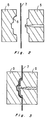
- a transfer member 7 has a releasable layer 9, a pattern layer 10, and an adhesive layer 11, which are sequentially formed on a substrate sheet 8.
- the transfer member 7 is capable of generating matted pattern or functional thin film on the surface of the in-mold molded product when transferred to it.
- the substrate sheet 8 of the transfer member 7 is superficially provided with matted fine projections and recesses 4.
- the substrate sheet 8 is a sheet normally usable for a transfer member and made of any plastic film such as polyethylene terephthalate film, polypropylene film, polyethylene film, nylon film, cellophane film, or a composite film consisting of plastic film and paper.
- a layer with fine projections and recesses is formed on the substrate sheet 8.
- the substrate sheet 8 may be superficially coated with a resinous layer containing fine powder particles of silica, calcium carbonate, polyethylene wax, or glass beads, by applying a printing process, for example.
- a resinous layer containing fine powder particles of silica, calcium carbonate, polyethylene wax, or glass beads
- a printing process for example.
- thermoplastic resin any thermosetting resin such as polyurethane resin, melamine resin, or epoxy resin, or any of those which are curable by irradiating ultra-violet rays or electronic rays, such as methyl methacrylate, may also be made available for composing the resinous layer for coating the substrate sheet 8.
- the substrate sheet 8 may also contain fine powder of loadings which can be mixed into the above plastic film during its formation.
- the substrate sheet 8 may be composed of any plastic film cited above containing projections and recesses 4 which are formed by applying to the surface of the plastic film any physical means such as the sand blast process or the chemical etching process.
- the matted regions may be formed on the entire surface of the substrate sheet 8 or only in local regions so that matted and lustered regions can be displayed by effectively combining the pattern with the design, such as the shape of the molded product.
- the release layer 9 is provided on the whole surface of the substrate sheet 8. After completing the transfer process, the release layer 9 is stripped off from the substrate sheet 8. As a result, in correspondence with those projections and recesses formed on the surface of the substrate sheet 8, projections and recesses complementary to those of the substrate sheet 8 are formed on the entire surface of the release layer 9. After completing the transfer process, the release layer 9 itself makes up the surface of the objective molded product, and thus, the release layer 9 also has the function to protect the transfer layer 2.
- the release layer 9 is formed on the substrate sheet 8 by applying any conventional printing means such as roll-coating process, gravure printing process, or screen printing process.
- Thermoplastic resin such as acrylic resin or polyvinyl resin may be used for the release layer 9.
- the release layer 9 may also be composed of thermosetting resin such as polyurethane resin or epoxy resin, or any resin curable by applying ultra-violet rays or electronic rays, such as methyl methacrylate.
- the adhesive layer 11 secures the transfer layer 2 of the transfer member 7 to a product to which it is to be transferred.
- Either thermosensitive resin or pressure-sensitive resin compatible with the material of the molded plastic product 1 to which it is to be transferred is properly selected for the adhesive layer 11.
- AS acrylonitrile-styrene
- acrylic resin or polyvinyl resin is suitable.
- polypropylene resin either chlorinated polypropylene resin or ethylene-vinyl acetate copolymer resin is suitable.
- An arbitrary pattern layer 10 or an evaporated metallic layer is provided between the release layer 9 and the adhesive layer 11 optionally covering the entire surface or local regions.
- the pattern layer 10 is formed by applying any conventional printing means such as a gravure printing process or a screen printing process using ink composed of resin containing either pigment or dye and a variety of additives.
- the evaporated metallic layer is provided in order to visually appeal the sense of the matted effect yielded by the fine projections and recesses 4 formed on the surface of the release layer 9.
- the evaporated metallic layer can be generated by evaporating metal such as aluminum, chrome, or nickel by applying either a vacuum deposition process, or an ion plating deposition process, or a sputtering process, for example.
- a pre-anchor layer may be provided between the release layer 9 and the evaporated metallic layer. If the layer used for the formation of the projections and recesses 4 is provided below the pre-anchor layer, the layer containing these projections and recesses 4 reduces the matting effect. Furthermore, in order to promote adhesion between the evaporated metallic layer and the adhesive layer 11, a post-anchor layer may be provided between the evaporated metallic layer and the adhesive layer 11 as required.
- the materials of the release layer 9, the pattern layer 10, the layer containing the projections and recesses, the evaporated metallic layer, the adhesive layer 11, and the pre-anchor and post-anchor layers are preferably selected to obtain good adhesion between the adjacent layers.
- a mold unit 5 suitable for executing the in-mold molding operation is composed of movable and stationary mold components.
- the transfer member 7 is secured to the movable mold component.
- the cavity section 6 is defined by closing the movable and stationary mold components 5.
- Projections and recesses 3 needed for the formation of the matted effect on the surface of the in-mold molded product are provided on the product-side surface of the movable mold component 5 which is in contact with the mat transfer member 7 held in the cavity section 6. These projections and recesses 3 are respectively greater than the projections and recesses 4 formed by the mat transfer member 7.
- Resinous material for molding the product is not directly brought into contact with the surface of the movable mold component defining part of the cavity section 6, but instead, the transfer member 7 is held between the movable and stationary mold components 5, and thus, if excessively fine projections and recesses are provided, then, the projected and recessed surface cannot be formed on the surface of the molded product.
- An in-mold molding operation is executed using the mat transfer member 7 and the mold unit 5.
- the mat transfer member 7 is secured to a predetermined position of the mold unit 5. If the matted surface is formed in local regions, the matted sections of both the mat transfer member 7 and the mold unit 5 are made to correctly match with each other by the use of a film feeding device having a positioning mechanism.
- the mold unit 5 is closed, and then the selected resinous material is injected. After cooling off the injected resin, the mold unit 5 is opened to extract the molded piece therefrom.
- the substrate sheet 8 of the transfer member 7 is stripped off from the molded piece, whereby the in-mold molded piece having the matted surface is obtained.
- the transfer member 7 provides very fine projections and recesses 4 on the surface of the projections and recesses 3 of the molded piece produced by the mold unit 5.
- the tips of all the projections 3 formed by the mold unit 5 are rounded because the thickness of the substrate sheet 8 prevents it from contacting the lower projections and the shallow recesses of the projections and recesses 3 of the mold unit 5.
- the whole matted surface remains free from incurring superficial damage, thus securely producing damage-free matted surface.
- the surface of the transfer layer 2 formed by the transfer member 7 has very fine projections and recesses 4, thus providing a very satisfactory matted effect.
- a transfer member is secured. Then, the in-mold molding operation is executed using of AS resin (acrylonitrile-styrene resin) under the following injection conditions.
- AS resin acrylonitrile-styrene resin
- Mold temperature 50°C Cylinder temperature: 220°C Injection pressure: 1,190kg/cm 2 Retained pressure: 850kg/cm 2 Number of the rotation of the screw: 55r.p.m. The injection speed is maximized in the molding machine.
- a transfer member including a substrate sheet with 38 microns thickness and having dual-phase matted effect is secured. Then, the in-mold molding operation is executed by the use of AS resin.
- the molded product exhibits the dual-phase matted effect in local regions, and yet, produces a surface with fully satisfactory physical properties and bearing lustered regions and noticeable design effect.
- a mat transfer member including a substrate sheet with 38 microns thickness and having dual-phase matted effect is secured. Then, the in-mold molding operation is executed by the use of AS resin.
- the molded product exhibits the dual-phase matted effect in local regions, and yet, produces the surface with fully satisfactory physical properties and bearing lustered regions and noticeable design effect.
- the in-mold molded product with the matted surface provides a transfer layer containing finer projections and recesses over projections and recesses on the surface of the plastic molded product, the projections and recesses of the transfer layer being finer than those of the plastic molded product, whereby projections and recesses having dual-phase sizes are formed on the plastic molded product. Therefore, the in-mold molded product is resistant to superficial damage and has a stain-free surface with the excellent matted effect.
- the method for manufacturing the in-mold molded product with a matted surface according to the invention is such that using both a transfer member capable of forming fine projections and recesses for producing the matted effect and a mold unit on which projections and recesses greater than those of the transfer member are formed at a cavity section thereof, the mat transfer member is secured inside of the mold unit and then resin is injected to perform the in-mold molding operation.
- the above-described in-mold molded product can be easily produced.
Abstract
Claims (4)
- Article moulé dans un moule, comprenant:un article moule (1) en matière plastique dont au moins une partie de la surface comporte des reliefs et des creux moulés (3) permettant de produire un effet de surface mate,et une couche de transfert (2) collée au moins à ladite partie de la surface afin d'épouser lesdits reliefs et creux moulés (3),ladite couche de transfert (2) étant pourvue d'une surface mate constituée par de petits reliefs et creux (4) plus petits que lesdits reliefs et creux moulés (3),
grâce à quoi ladite partie de surface de l'article moulé (1) en matière plastique présente un double effet de mat obtenu par la combinaison desdits reliefs et creux moulés (3) et desdits reliefs et creux plus petits (4) de la couche de transfert (2). - Article selon la revendication 1, dans lequel la couche de transfert (2) est une multicouche comprenant au moins une couche de séparation (9) séparable d'une feuille de substrat (8) et pourvue de ladite surface mate, une couche (10) à motif et une couche adhésive (11).
- Procédé pour fabriquer un article moulé dans un moule, comprenant les étapes consistant à:réaliser un dispositif de moule (5) dont une zone prédéterminée de la surface (6) de cavité comporte des reliefs et des creux (3) permettant de produire un effet de surface mate sur l'article moulé;fixer un élément de transfert (7) au moins sur ladite zone prédéterminée de la surface (6) de cavité du dispositif de moule (5), ledit élément de transfert comportant une couche de transfert séparable (2) ayant de petits reliefs et creux (4) plus petits que les reliefs et creux (3) de la surface (6) de cavité du dispositif de moule (5);injecter une résine dans la cavité du dispositif de moule (5) pour effectuer une opération dans le moule afin d'obtenir que l'article moulé dans le moule ait une surface à reliefs et creux moulés (3) complémentaires de ceux de la surface (6) de cavité du moule et que sa couche de transfert (2) séparée de l'élément de transfert (7) couvre ladite surface de façon à produire un double effet de mat sur l'article par une combinaison desdits reliefs et creux moulés (3) et desdits reliefs et creux plus petits de la couche de transfert (2).
- Procédé selon la revendication 3, dans lequel ledit élément de transfert (7) comporte une feuille de substrat (8), une couche de séparation (9), une couche (10) à motif et une couche adhésive (11), l'élément de transfert (7) étant disposé à l'intérieur du dispositif de moule (5) pour que la feuille de substrat (8) vienne au contact de la résine injectée, et la feuille de substrat (8) étant détachée après que l'article a été sorti du dispositif de moule (5).
Applications Claiming Priority (1)
| Application Number | Priority Date | Filing Date | Title |
|---|---|---|---|
| PCT/JP1989/001209 WO1991008096A1 (fr) | 1989-12-01 | 1989-12-01 | Article moule dans un moule, presentant une surface matie et procede de production |
Publications (3)
| Publication Number | Publication Date |
|---|---|
| EP0456822A1 EP0456822A1 (fr) | 1991-11-21 |
| EP0456822A4 EP0456822A4 (en) | 1993-12-29 |
| EP0456822B1 true EP0456822B1 (fr) | 1997-03-19 |
Family
ID=13958971
Family Applications (1)
| Application Number | Title | Priority Date | Filing Date |
|---|---|---|---|
| EP89913243A Expired - Lifetime EP0456822B1 (fr) | 1989-12-01 | 1989-12-01 | Article moule dans un moule, presentant une surface mate et procede de production |
Country Status (5)
| Country | Link |
|---|---|
| US (1) | US5639536A (fr) |
| EP (1) | EP0456822B1 (fr) |
| KR (1) | KR940011142B1 (fr) |
| DE (1) | DE68927893T2 (fr) |
| WO (1) | WO1991008096A1 (fr) |
Cited By (1)
| Publication number | Priority date | Publication date | Assignee | Title |
|---|---|---|---|---|
| DE10054490A1 (de) * | 2000-11-03 | 2002-05-08 | Bayerische Motoren Werke Ag | Verfahren zum Herstellen eines Kunststoffbauteiles |
Families Citing this family (30)
| Publication number | Priority date | Publication date | Assignee | Title |
|---|---|---|---|---|
| US5258098A (en) * | 1991-06-17 | 1993-11-02 | Cycam, Inc. | Method of production of a surface adapted to promote adhesion |
| US6019923A (en) * | 1992-08-25 | 2000-02-01 | Hp-Chemie Pelzer Research & Development Ltd. | Process for manufacturing decorable moulded parts |
| KR100186660B1 (ko) * | 1994-06-22 | 1999-05-15 | 유미꾸라 레이찌 | 무광택상의 합성 수지 사출 성형품 및 그의 성형법 |
| EP0960719B1 (fr) * | 1996-06-28 | 2004-09-01 | Kaneka Corporation | Procede de fabrication d'un corps en resine synthetique a peau moule par expansion dans un moule, et moule en metal utilise dans ce procede |
| KR100559677B1 (ko) * | 1997-08-12 | 2006-03-10 | 니폰샤신인사츠가부시키가이샤 | 전사재, 표면보호시트 및 성형품의 제조방법 |
| US6558496B1 (en) | 1997-11-28 | 2003-05-06 | Eschmann-Stahl Gmbh & Co., Kg | Rapid texture prototyping |
| GB9725102D0 (en) * | 1997-11-28 | 1998-01-28 | Gravutex Limited | Rapid texture prototyping |
| US6248441B1 (en) | 1999-03-24 | 2001-06-19 | Custom-Pak, Inc. | Method for enhancing the three-dimensional effect of a raised plastic surface using in-mold labeling and the label used therewith |
| DE19851117C5 (de) * | 1998-11-06 | 2006-05-24 | Ise Intex Gmbh | Verfahren zum Herstellen eines Formteils |
| GB2345021A (en) | 1998-12-22 | 2000-06-28 | Nokia Mobile Phones Ltd | Matt surface display window |
| TW580426B (en) * | 1999-06-29 | 2004-03-21 | Four Pillars Entpr Co Ltd | Method for processing a film |
| US6440546B1 (en) | 1999-10-13 | 2002-08-27 | Ream Industries Corp. | Gloss-adjusting mask layer with particulate filler |
| DE10014432A1 (de) * | 2000-03-16 | 2001-09-20 | Volkswagen Ag | Verfahren zur Herstellung eines beschichteten Kunststoff-Formteils sowie Kunststoff-Formteil |
| TWI230002B (en) * | 2000-10-17 | 2005-03-21 | Nissha Printing | Antireflective molded product and its manufacture method, mold for antireflective molded product |
| DE102004012937A1 (de) * | 2004-03-17 | 2005-10-06 | Volkswagen Ag | Verfahren zur Herstellung eines Verbundmaterials |
| US20080105677A1 (en) * | 2004-09-16 | 2008-05-08 | 2089275 Ontario Ltd. | Methods for producing a container having a substantially two dimensional image on a surface having a topographical texture, and a container bearing such an image |
| US8053057B2 (en) * | 2005-09-12 | 2011-11-08 | The United States Of America As Represented By The Secretary Of The Navy | Material with improved adhesion surface |
| DE102005057181A1 (de) * | 2005-11-29 | 2007-06-06 | Lanxess Deutschland Gmbh | Verbinden von faserverstärktem Material mit einem Spritzgussmaterial |
| US20070218255A1 (en) * | 2006-03-20 | 2007-09-20 | Gray Lorin S Iii | Films for decorating glass and methods of their production |
| JP2011136458A (ja) * | 2009-12-28 | 2011-07-14 | Three M Innovative Properties Co | 加飾成形物品の製造方法 |
| US9434096B2 (en) | 2010-10-05 | 2016-09-06 | Kaneka Corporation | Decorative resin sheet, and molded resin article and process for production thereof |
| KR20140000549A (ko) * | 2012-06-25 | 2014-01-03 | 삼성전자주식회사 | 하우징 가공 방법 및 장치 |
| KR102086794B1 (ko) * | 2013-05-31 | 2020-04-14 | 삼성전자주식회사 | 케이스 프레임 제조 방법 |
| US10687956B2 (en) | 2014-06-17 | 2020-06-23 | Titan Spine, Inc. | Corpectomy implants with roughened bioactive lateral surfaces |
| TWI726940B (zh) | 2015-11-20 | 2021-05-11 | 美商泰坦脊柱股份有限公司 | 積層製造整形外科植入物之方法 |
| CN105643464B (zh) * | 2015-12-25 | 2019-06-07 | 深圳市沃特沃德股份有限公司 | 一种移动终端壳体的加工方法及壳体模具 |
| US20170314838A1 (en) | 2016-04-29 | 2017-11-02 | Thermo King Corporation | Method of manufacturing an enclosure for a transport refrigeration unit, transport refrigeration unit and transport unit |
| US10821000B2 (en) | 2016-08-03 | 2020-11-03 | Titan Spine, Inc. | Titanium implant surfaces free from alpha case and with enhanced osteoinduction |
| US10882259B2 (en) * | 2017-06-01 | 2021-01-05 | Thermo King Corporation | Manufacturing method for an aesthetic structural part |
| CN109957197A (zh) * | 2019-03-15 | 2019-07-02 | 安徽世轩机械科技有限公司 | 一种树脂产品中的树脂沙子的制作方法 |
Citations (1)
| Publication number | Priority date | Publication date | Assignee | Title |
|---|---|---|---|---|
| JPS5515888A (en) * | 1978-07-22 | 1980-02-04 | Ryuji Uematsu | Method of forming pattern of decorative material used in synthetic resin product |
Family Cites Families (16)
| Publication number | Priority date | Publication date | Assignee | Title |
|---|---|---|---|---|
| US4229497A (en) * | 1977-11-03 | 1980-10-21 | Maso-Therm Corporation | Composite module with reinforced shell |
| US4183991A (en) * | 1977-05-02 | 1980-01-15 | Rohm And Haas Company | Process for preparing highly filled acrylic articles |
| US4160798A (en) * | 1977-05-09 | 1979-07-10 | Lawrence Price | Release coatings |
| JPS56109718A (en) * | 1980-02-05 | 1981-08-31 | Kitai Seisakusho:Kk | Molding of product in continuous length having decorative pattern on group of recessed and protruded parts on surface thereof |
| JPS57129731A (en) * | 1981-02-06 | 1982-08-11 | Matsushita Electric Ind Co Ltd | Decoration of molding |
| JPS57150551A (en) * | 1981-03-12 | 1982-09-17 | Yoshida Kogyo Kk <Ykk> | Unevenly decorated patterned container and its manufacture |
| JPS59202832A (ja) * | 1983-05-04 | 1984-11-16 | Dainippon Printing Co Ltd | 成形絵付方法および成形絵付装置 |
| US4544578A (en) * | 1983-11-23 | 1985-10-01 | Chem-Pak, Inc. | Method of touching up surface-blemished matt-finished surface grained colored molded plastic parts |
| US5000990A (en) * | 1985-08-22 | 1991-03-19 | The Budd Company | One piece molded composite part and method of manufacture |
| JPS62256620A (ja) * | 1986-04-30 | 1987-11-09 | Dainippon Printing Co Ltd | 樹脂製品の成形方法 |
| DE3631232A1 (de) * | 1986-09-13 | 1988-03-24 | Hoechst Ag | Mehrschichtfolie als trennfolie zur herstellung dekorativer schichtstoffplatten |
| JPS6391215A (ja) * | 1986-10-06 | 1988-04-21 | Nissei Plastics Ind Co | 転写成形方法 |
| JPS63224918A (ja) * | 1987-03-13 | 1988-09-20 | Toyoda Gosei Co Ltd | 模様付き成形品の製造方法 |
| JPH0195018A (ja) * | 1987-10-07 | 1989-04-13 | Mitsubishi Gas Chem Co Inc | 凹凸面模様入り成形品の製造法 |
| JPH01295812A (ja) * | 1988-05-25 | 1989-11-29 | Ado Union Kenkyusho:Kk | 柄付射出成形品及びその製造方法 |
| JPH01301316A (ja) * | 1988-05-31 | 1989-12-05 | Nissha Printing Co Ltd | 艶消し表面を有するインモールド成型品とその製造方法 |
-
1989
- 1989-12-01 DE DE68927893T patent/DE68927893T2/de not_active Expired - Lifetime
- 1989-12-01 EP EP89913243A patent/EP0456822B1/fr not_active Expired - Lifetime
- 1989-12-01 KR KR1019910700791A patent/KR940011142B1/ko not_active IP Right Cessation
- 1989-12-01 WO PCT/JP1989/001209 patent/WO1991008096A1/fr active IP Right Grant
-
1994
- 1994-09-20 US US08/308,958 patent/US5639536A/en not_active Expired - Lifetime
Patent Citations (1)
| Publication number | Priority date | Publication date | Assignee | Title |
|---|---|---|---|---|
| JPS5515888A (en) * | 1978-07-22 | 1980-02-04 | Ryuji Uematsu | Method of forming pattern of decorative material used in synthetic resin product |
Cited By (1)
| Publication number | Priority date | Publication date | Assignee | Title |
|---|---|---|---|---|
| DE10054490A1 (de) * | 2000-11-03 | 2002-05-08 | Bayerische Motoren Werke Ag | Verfahren zum Herstellen eines Kunststoffbauteiles |
Also Published As
| Publication number | Publication date |
|---|---|
| KR920702832A (ko) | 1992-10-28 |
| DE68927893D1 (de) | 1997-04-24 |
| EP0456822A4 (en) | 1993-12-29 |
| EP0456822A1 (fr) | 1991-11-21 |
| KR940011142B1 (ko) | 1994-11-24 |
| WO1991008096A1 (fr) | 1991-06-13 |
| DE68927893T2 (de) | 1997-08-07 |
| US5639536A (en) | 1997-06-17 |
Similar Documents
| Publication | Publication Date | Title |
|---|---|---|
| EP0456822B1 (fr) | Article moule dans un moule, presentant une surface mate et procede de production | |
| US6391242B2 (en) | Foil-covered plastic part and method of making same | |
| EP2080426B1 (fr) | Boitier d'equipement electronique et procede de fabrication de celui-ci | |
| US8354050B2 (en) | Co-molded direct flock and flock transfer and methods of making same | |
| JP7210869B2 (ja) | 電子製品ケースの製造方法 | |
| AU2001277991B2 (en) | Co-molded flock transfer and method | |
| EP1304173B1 (fr) | Procédé de formation d'un produit moulé à base de résine avec une surface comportant une lustre métallique | |
| CN1557622A (zh) | 在模内完成表面覆膜装饰面的塑料件及其制作方法 | |
| US11628605B2 (en) | Method for producing a shaped plastic part having a decorated surface | |
| JP4488485B2 (ja) | 金属光沢シートとその製造方法、金属光沢成形品の製造方法 | |
| JPH01301316A (ja) | 艶消し表面を有するインモールド成型品とその製造方法 | |
| JPH09267357A (ja) | 艶消しインサート成形品およびその製造方法 | |
| JP2000084972A (ja) | 成形同時絵付シートと成形同時絵付成形品の製造方法 | |
| JPH01141014A (ja) | ヘアライン表面を有するインモールド成型品の製造方法 | |
| JPH09131749A (ja) | インサートフィルムとこれを用いたインサート成形品の製造方法 | |
| JP3710858B2 (ja) | インサート成形品の製造方法およびインサートフィルム | |
| JPH0825789A (ja) | 転写シート | |
| JPH10180801A (ja) | 絵付シートとこれを用いた絵付成形品の製造方法 | |
| JP3684276B2 (ja) | ヘアライン目インサートフィルム、ヘアライン目インサート成形品の製造方法 | |
| JP2003203537A (ja) | キーシート部材とその製造方法 | |
| JPH11342700A (ja) | 装飾模様シート及び装飾模様を有する合成樹脂成形品 | |
| JP2000052375A (ja) | 成形同時絵付成形品の製造方法 | |
| JPH10180796A (ja) | 装飾された凹凸文字部を有する成形同時絵付け品の製造方法 | |
| JP2567793B2 (ja) | 転写材 | |
| JP2010052353A (ja) | ヘアライン意匠を有する転写シートと転写成形品の製造方法 |
Legal Events
| Date | Code | Title | Description |
|---|---|---|---|
| PUAI | Public reference made under article 153(3) epc to a published international application that has entered the european phase |
Free format text: ORIGINAL CODE: 0009012 |
|
| 17P | Request for examination filed |
Effective date: 19910731 |
|
| AK | Designated contracting states |
Kind code of ref document: A1 Designated state(s): DE FR GB IT NL |
|
| A4 | Supplementary search report drawn up and despatched |
Effective date: 19931108 |
|
| AK | Designated contracting states |
Kind code of ref document: A4 Designated state(s): DE FR GB IT NL |
|
| 17Q | First examination report despatched |
Effective date: 19950404 |
|
| GRAG | Despatch of communication of intention to grant |
Free format text: ORIGINAL CODE: EPIDOS AGRA |
|
| GRAH | Despatch of communication of intention to grant a patent |
Free format text: ORIGINAL CODE: EPIDOS IGRA |
|
| GRAH | Despatch of communication of intention to grant a patent |
Free format text: ORIGINAL CODE: EPIDOS IGRA |
|
| GRAA | (expected) grant |
Free format text: ORIGINAL CODE: 0009210 |
|
| AK | Designated contracting states |
Kind code of ref document: B1 Designated state(s): DE FR GB IT NL |
|
| REF | Corresponds to: |
Ref document number: 68927893 Country of ref document: DE Date of ref document: 19970424 |
|
| ET | Fr: translation filed | ||
| ITF | It: translation for a ep patent filed |
Owner name: MODIANO & ASSOCIATI S.R.L. |
|
| PLBE | No opposition filed within time limit |
Free format text: ORIGINAL CODE: 0009261 |
|
| STAA | Information on the status of an ep patent application or granted ep patent |
Free format text: STATUS: NO OPPOSITION FILED WITHIN TIME LIMIT |
|
| 26N | No opposition filed | ||
| REG | Reference to a national code |
Ref country code: GB Ref legal event code: IF02 |
|
| PGFP | Annual fee paid to national office [announced via postgrant information from national office to epo] |
Ref country code: NL Payment date: 20081215 Year of fee payment: 20 |
|
| PGFP | Annual fee paid to national office [announced via postgrant information from national office to epo] |
Ref country code: FR Payment date: 20081212 Year of fee payment: 20 |
|
| PGFP | Annual fee paid to national office [announced via postgrant information from national office to epo] |
Ref country code: DE Payment date: 20081127 Year of fee payment: 20 |
|
| PGFP | Annual fee paid to national office [announced via postgrant information from national office to epo] |
Ref country code: GB Payment date: 20081126 Year of fee payment: 20 |
|
| PGFP | Annual fee paid to national office [announced via postgrant information from national office to epo] |
Ref country code: IT Payment date: 20081229 Year of fee payment: 20 |
|
| REG | Reference to a national code |
Ref country code: GB Ref legal event code: PE20 Expiry date: 20091130 |
|
| NLV7 | Nl: ceased due to reaching the maximum lifetime of a patent |
Effective date: 20091201 |
|
| PG25 | Lapsed in a contracting state [announced via postgrant information from national office to epo] |
Ref country code: NL Free format text: LAPSE BECAUSE OF EXPIRATION OF PROTECTION Effective date: 20091201 |
|
| PG25 | Lapsed in a contracting state [announced via postgrant information from national office to epo] |
Ref country code: GB Free format text: LAPSE BECAUSE OF EXPIRATION OF PROTECTION Effective date: 20091130 |