EP0454960A2 - Cremone - Google Patents
Cremone Download PDFInfo
- Publication number
- EP0454960A2 EP0454960A2 EP91102728A EP91102728A EP0454960A2 EP 0454960 A2 EP0454960 A2 EP 0454960A2 EP 91102728 A EP91102728 A EP 91102728A EP 91102728 A EP91102728 A EP 91102728A EP 0454960 A2 EP0454960 A2 EP 0454960A2
- Authority
- EP
- European Patent Office
- Prior art keywords
- latch
- lock
- particular according
- nut
- espagnolette
- Prior art date
- Legal status (The legal status is an assumption and is not a legal conclusion. Google has not performed a legal analysis and makes no representation as to the accuracy of the status listed.)
- Granted
Links
Images


Classifications
-
- E—FIXED CONSTRUCTIONS
- E05—LOCKS; KEYS; WINDOW OR DOOR FITTINGS; SAFES
- E05B—LOCKS; ACCESSORIES THEREFOR; HANDCUFFS
- E05B63/00—Locks or fastenings with special structural characteristics
- E05B63/04—Locks or fastenings with special structural characteristics for alternative use on the right-hand or left-hand side of wings
- E05B63/044—Locks or fastenings with special structural characteristics for alternative use on the right-hand or left-hand side of wings with reversible bolt or bolt head
-
- E—FIXED CONSTRUCTIONS
- E05—LOCKS; KEYS; WINDOW OR DOOR FITTINGS; SAFES
- E05C—BOLTS OR FASTENING DEVICES FOR WINGS, SPECIALLY FOR DOORS OR WINDOWS
- E05C9/00—Arrangements of simultaneously actuated bolts or other securing devices at well-separated positions on the same wing
- E05C9/04—Arrangements of simultaneously actuated bolts or other securing devices at well-separated positions on the same wing with two sliding bars moved in opposite directions when fastening or unfastening
- E05C9/041—Arrangements of simultaneously actuated bolts or other securing devices at well-separated positions on the same wing with two sliding bars moved in opposite directions when fastening or unfastening with rack and pinion mechanism
-
- E—FIXED CONSTRUCTIONS
- E05—LOCKS; KEYS; WINDOW OR DOOR FITTINGS; SAFES
- E05C—BOLTS OR FASTENING DEVICES FOR WINGS, SPECIALLY FOR DOORS OR WINDOWS
- E05C9/00—Arrangements of simultaneously actuated bolts or other securing devices at well-separated positions on the same wing
- E05C9/04—Arrangements of simultaneously actuated bolts or other securing devices at well-separated positions on the same wing with two sliding bars moved in opposite directions when fastening or unfastening
- E05C9/047—Arrangements of simultaneously actuated bolts or other securing devices at well-separated positions on the same wing with two sliding bars moved in opposite directions when fastening or unfastening comprising key-operated locks, e.g. a lock cylinder to drive auxiliary deadbolts or latch bolts
-
- E—FIXED CONSTRUCTIONS
- E05—LOCKS; KEYS; WINDOW OR DOOR FITTINGS; SAFES
- E05C—BOLTS OR FASTENING DEVICES FOR WINGS, SPECIALLY FOR DOORS OR WINDOWS
- E05C9/00—Arrangements of simultaneously actuated bolts or other securing devices at well-separated positions on the same wing
- E05C9/20—Coupling means for sliding bars, rods, or cables
Definitions
- the invention relates to an espagnolette lock according to the preamble of claim 1.
- the object of the invention is based on the task of designing an espagnolette lock of the type in question in a technically simple manner in such a way that a reduced space above the trap requires less space on the lock housing without reducing the espagnolette.
- an espagnolette lock of the aforementioned type is created, the lock housing of which can be produced in a reduced overall height, combined with a corresponding saving in material.
- the change lever spring is advantageously designed as a compression spring. Its end on the link side is in a non-positive connection with one arm of the deflecting member, in such a way that it is tensioned when the nut is actuated to withdraw the trap.
- the spring wire passing through the compression spring serves for the non-positive connection, which extends beyond the fastening pin on the deflection member into one the torsion spring loading section continues. Accordingly, the change lever spring works in two ways.
- the change lever spring can be made of the same material in that the spring wire connects to a bend in the last thread of the compression spring.
- the end of the compression spring opposite the bend is supported on a stationary abutment.
- the latter is part of a carrier plate of the gear transmission, so that already existing components are also used for the support function.
- the compression spring is loaded when the handle is moved to retract the latch by a third arm of the deflecting member via the nut actuating slide that is inevitably carried along.
- the nut is located in a free space of the carrier plate, is loaded by a return spring and is in meshing engagement with the nut. Therefore, the nut actuating slide returns to the starting position after each shift via this return spring and tooth engagement.
- the nut is arranged in a bearing housing which is interchangeably inserted in the lock housing. Depending on the distance, a corresponding bearing housing is used, while the nut actuating slide can keep its structure. Then the tooth of the nut engages in the respective window of the nut actuating slide.
- the bearing housing can also have a fitting plate screw passage hole arranged below the nut.
- the secure fixation of a hardware label is therefore always guaranteed.
- the aforementioned Nut assembly can also be assigned to espagnolette locks with different backsets, without modification. This applies even to espagnolette locks with the smallest possible backset.
- the fact that the lower end of the intermediate link is articulated to the actuating arm of the change lever arrangement also contributes to this.
- the latter is spring-loaded against the direction of a ring gear comprising the locking member hub of a locking cylinder and can be driven into the ring gear actuation area by a control edge of the connecting rod connecting slide.
- the control edge accordingly moves parallel to the cuff and not, as in known designs, in the direction of the cuff, which helps to save space.
- the actuating arm When the latch is pulled back by alternating actuation, the actuating arm is first activated and then taken along by the sprocket actuating area. With a closing rotation in the other direction in order to be able to lock the bolt, there is no engagement between the actuating arm and the gear rim actuating area. The correct closing operation of the espagnolette lock can therefore not be avoided.
- the area of use of the espagnolette lock can be increased by a pin that can be uncoupled through a hole in the lock cover or lock base between the latch-side arm of the deflection member and a slot equipped with a corresponding play of the latch, which can be turned around its longitudinal axis.
- the trap is given particularly good guidance by a guide groove which crosses into the slot on at least one broad side of the trap tail and into which an adapted guide projection of the lock top and / or lock base protrudes.
- An advantageous further development is to be seen in giving the angled leg directed towards the cuff an arrow-shaped profile in cross section with the Trap of the arrowhead. So that these parts can be pushed into each other despite the trap being reversible, the latch head has contour-like grooves on both narrow sides.
- the turning of the trap is also made possible by the fact that each prong of the forked tongue has a slot, which slots are offset from one another by the turning shift.
- either one or the other slot is used in that the pin screwed into the trap arm of the deflecting member dips into the slot of the trap tail with its end projecting beyond the trap arm. Turning the trap requires pushing the trap back so that the pin is aligned with the hole in the lock top or bottom. Then the pin can be unscrewed and then the latch can be removed and turned. Then the pin is screwed in again, its end then protruding into the other slot of the trap tail.
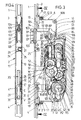
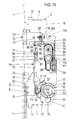
- the espagnolette lock has a lock housing 2 connected to a cuff 1.
- the cuff 1 fastened to the one narrow side of the lock housing 2 has a greater length than the lock housing 2 and extends over an upper and a lower drive rod 3 or, respectively, emerging from the lock housing 2. 4.
- the latter are with Bolt members 5 which cooperate with frame-side counter-locking parts, not shown.
- the fastening projections 9 projecting over the narrow side walls 6, 7 have a trapezoidal shape such that the base of the trapezium faces the interior of the lock housing.
- the lock base 10 and the lock cover 11 running parallel thereto form insertion pockets 12 and 13 on the narrow side walls.
- the pocket 12 formed by the lock base 10 is obtuse-angled.
- the angle section 12 ′′ is equipped with a passage opening 14 which is aligned with a threaded bore 15 of the fastening projection 9. Otherwise, this threaded bore runs parallel to the cuff 1.
- the other insertion pocket 13 in turn also has an angular shape.
- the angle leg 13 'starting directly from the castle ceiling 11 is supported on the facing oblique flank of the trapezoidal fastening projection 9.
- There the angle leg 13 '' is equipped with a hole 16.
- a bolt 17 which extends through the insertion pockets 12, 13 and enters the threaded bore 15 of the fastening projection 9 and is designed as a screw, Castle floor 10 and castle ceiling 11 can be connected to one unit.
- the outer surface 18 of the bearing blocks 8 is convexly curved. Within this convex curvature also extend the outer surface of the fastening projections 9 and the insertion pockets 12, 13 formed by bends, cf. 5 and 6. This makes it possible to produce pockets on the doors which are adapted to the outline of the lock housing at the height of the bearing blocks 8.
- Each bearing block 8 has a projection 19 with an oval cross section for fixing it on the cuff 1, which is inserted into a shape-adapted recess 20 of the cuff and riveted there, cf. 5 and 14 in particular.
- the bearing blocks 8 form centering brackets 22 which are immersed in shape-matched edge recesses in the lock base 10 and lock cover 11.
- the aforementioned centering tabs 22 are flush with the outer surfaces of the lock base 10 and lock cover 11.
- a threaded bore 25 is provided in the projection 24 for receiving a bolt 26, which is also designed as a screw. The latter runs parallel to the cuff 1, but is oriented at right angles to the other bolts 17, since it is screwed in through a hole 27 in the lock base 10 is.
- differently designed cuffs 1 with connecting rods 3, 4 can be connected to lock housings 2, which may also have different designs, with easy assembly.
- the lower drive rod 4 is forked in the region of the section crossing the bearing block 8.
- a longitudinal slot 29 is formed by the two fork tines 4 ', 4' '.
- Each fork 4 '. 4 ′′ is provided with an angled end section E, E ′, which rest on the lock base 10 and plunge into form-fitting coupling recesses 31, 32 of a drive rod connecting slide 28 lying flat on the lock base 10.
- the aforementioned longitudinal slot 29 extends, moreover, at the level of a through hole 30 of the cuff 1 for a locking cylinder fastening screw 30 '.
- a trap 33 is guided between the upper bearing block 8 and the projection 24. This has a head 33 'which extends through a latch opening 34 of the cuff 1 and is equipped with a latch slope, to which a latch tail 33' 'adjoins the housing.
- a bolt 35 is guided in the lock housing. Its locking head 35 'passes through a cross-section-adapted passage opening 36 of the cuff 1.
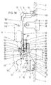
- the lock base 10 and the lock cover 11 hold a support plate 37 between them. This supports a toothed ring 39 in its lower region in a bore 38 facing the lock cover 11.
- the axis of rotation of the same is designated M1.
- the bore 38 is crossed by a locking cylinder insertion opening 40.
- the same is adapted to the outer contour of a profile locking cylinder 41.
- the axis of rotation M2 of the cylinder core of the profile locking cylinder used is eccentric to the axis of rotation M1, below the same, cf. Fig. 3.
- the aforementioned gear rim 39 has a radially directed gap 42 for engaging a lock bit 43 of the profile locking cylinder 41, shown in dash-dotted lines.
- Two output gearwheels 44, 45 mesh with the external teeth of the gear rim 39.
- the ring gear 39 meshes with at least one driven gear 44 or 45.
- the rotation of the output gears 44, 45 is transmitted to an end gear 51 with the interposition of further reduction gears 46-50.
- the axle journals for the same are also part of the carrier plate 37.
- the carrier plate 37 thus contains all the pinion functional units.
- the end wheel 51 meshes with the rack 52, which is parallel to the cuff 1 and is located at the free end of the connecting rod connecting slide 28.
- a further drive rod connecting slide 53 is guided in a parallel position opposite the rack 52. This forms a rack 54.
- the latter is in hook engagement 55 according to Fig. 10 assigned to the connecting rod connecting slide 53.
- the drive rod connecting slide 28, 53 are driven in opposite directions by the end gear 51 of the gear transmission.
- the aforementioned racks 52, 54 run on both sides of a section 37 ′ of the carrier plate 37 narrowed at the top.
- the drive rod connecting slide 53 controls the bolt closure with the interposition of a pivot lever 56 in such a way that first the drive rod connecting slide 53 leads the bolt exclusion and then the bolt 35 is taken along. As a result, only the locking members 5 can engage and bring about a tightening of the door, so that the locking bar 35 can then move freely into the striking plate recess facing it.
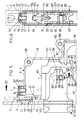
- the bolt 35 has on its bolt tail 35 'a run-up slope 57 which extends obliquely to the direction of movement of the bolt 35. This is formed by a lateral elevation 35' '' of the bolt tail 35 '', which elevation 35 '' 'leads on the lock base 10.
- the elevation 35 '' ' is surmounted by a guide pin 58 which protrudes into a longitudinal slot 59 of the lock base 10 which extends in the direction of exclusion of the bolt 35.
- the run-up slope 57 is followed by a recess 60 for a control arm 61 of the pivot lever 56. The end of the control arm 61 is, as can be seen from the figures, shaped like a club.
- the pivoted lever 56 which is mounted around a material-uniform pin 62 of the carrier plate 37, has on its side facing the connecting rod connecting slide 53 a toothed ring section 63, the teeth of which have a toothed strip 64 of the connecting rod connecting slide 53 Interact.
- the rack 64 is located on an extension 65 of the connecting rod connecting slide 53 or the rack 54. This extension 65 extends with the bolt 35 closed in front of a locking edge 66 of the bolt tail 35 '' cf. Fig. 9.
- the lower end edge 65 'of the extension 65 is also formed into an inclined flank which interacts with the ramp slope 57 in the manner described later.
- the terminal tooth 63 'of the ring gear section is immersed in a recess 67 of the drive rod connecting slide 53 which is approximately extended in accordance with the advance of the connecting rod connecting slide 53. This is a take-away game. When the game is over, the extension 65 has also released the bolt shift.
- the width of the bolt tail 35 ′′ corresponds approximately to that of the lateral elevation 35 ′′ ′′.
- the latter is slightly wider.
- the bolt tail 35 ′′ overlaps the driven wheels 44, 45, which, however, are located on the opposite side of the carrier plate 37.
- the bolt tail 35 ′′ extends in a cutout 68 of the carrier plate facing the lock base 10.
- the pivot pin 70 of an actuating arm 71 of a change lever arrangement W is immersed in an arch slot 69 of the support plate 37 arranged below the bolt 35 concentrically with the axis of rotation M1.
- the actuating arm 71 is designed as a hook pawl pointing in the circumferential direction of the ring gear 39.
- the longer lever arm of the actuating arm 71 forms one end Hook 72, which is arranged in the same plane as a support ring shoulder 73 of the ring gear 39.
- the hook 72 In the basic position of the drive rod lock illustrated in FIG. 3, which basic position allows the installation of a profile locking cylinder, the hook 72 is supported on the support ring shoulder 73.
- the latter forms a counter hook 74 projecting into the path of movement of the hook 72.
- a rod-shaped intermediate member 75 of the change lever arrangement W which runs approximately parallel to the cuff 1, articulates on the shorter lever arm of the actuating arm 71.
- Control edge 76 the end 75 'and thereby slightly pivots the actuating arm 71, which with its hook 72 comes against the support ring shoulder 73 of the ring gear 39.
- a leaf spring 77 clamped on the carrier plate 37 then acts on the end of the actuating arm 71 equipped with the hook 72.
- the upper end region 78 of the intermediate member 75 is plate-shaped and represents a plunger.
- An abutment 79 starting from the narrowed section 37 'of the carrier plate 37 and the opposite flank of the carrier plate section 37' serve to guide the end region 78.
- On the abutment 79 is supported one end of the designed as a compression spring Exchange lever spring 80 from.
- the opposite end of the compression spring 80, on the other hand, is supported on laterally projecting shoulders 81 of the end region 78.
- the fastening pin 83 is located at the free end of the first arm 86 of the deflection member 84. This forms above the end region 78 a driving shoulder 87, which lies in the path of movement of the end region 78 of the intermediate member 75.
- the spring wire 82 wrapping around the fastening pin 83 continues beyond the fastening pin 83 and forms a torsion spring section 82 'there loading the latch tail 33''.
- the change lever spring 80 fulfills the function of a latch spring due to its special design. Basically, the change lever spring 80 strives to displace the actuating arm 71 against the direction of the ring gear actuation area.
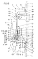
- a second arm 88 extends from the deflecting member 84, which projects between the fork tines of the forked latch tail 33 ′′.
- Each tine of the forked latch tail 33 ′′ each has a slot 89, 89 ′ which runs perpendicular to the direction of movement of the latch and which slots are offset from one another by the shifting movement.
- a pin 90 extends through the latch-side arm 88 of the deflection member 84 and establishes the driving connection to the latch 33.
- the pin 90 In the retracted position of the latch 33, the pin 90 is aligned with a hole 91 in the lock cover 11. Then the pin 90 designed as a grub screw can be unscrewed and the latch 33 can be turned around its longitudinal axis, so that the screwed-in pin 90 with its projecting end in dips the slot 89 'of the other fork.
- a guide groove 92 is provided on each broad side of the latch tail 33' ', into which a guide projection 93 protrudes from the lock cover 11 and lock base 10.
- the third arm 94 extends approximately diametrically opposite to the first arm 86 in order to engage a nut actuating slide 95.
- the latter is located in a space left by the carrier plate 37 within the lock housing 2 and is loaded by a return spring 96.
- the nut actuating slide 95 meshes with a nut 97 which is rotatably arranged in a two-part bearing housing 98 which is interchangeably inserted in the lock housing 2. Its length corresponds to a multiple of the nut diameter.
- the nut actuating slide 95 forms on the back a plurality of windows 99 for one engagement of a tooth 97 ', the nut 97. In the exemplary embodiment, the tooth 97' engages in the lower two windows 99 arranged one above the other.
- the bearing housing 98 forms the one located below the nut fitting bolt through hole 100 in the form of an elongated hole.
- This bearing housing 98 is designed with the nut 97 and the nut actuating slide 95 as a completely preassembled structural unit which can be inserted into a contour-matched recess A of the lock base and lock cover, in parallel extension to the narrowed support plate section 37 '.
- this unit is set to a distance between the axis of rotation of the nut and that of the cylinder core to 72 mm.
- FIG. 13 shows a modified bearing housing 98 'which is able to accommodate a nut 97 and the actuating slide 95 without changing the same. Then the tooth 97 'of the nut engages in the upper window 99 of the nut actuating slide 95. Below the nut bearing point, a fitting plate screw passage hole 100 'extends within the bearing housing 98'.
- a spacing of 92 mm between the axis of rotation of the locking cylinder and the axis of rotation of the nut 97 is realized by means of the structural unit illustrated in FIG. 13. Further spacing dimensions would be possible by designing the bearing housing accordingly.
- the basic positions of the nut are realized in a known manner by stops. Likewise, the rotary end positions of the nut stops are assigned, which are not dealt with in more detail.
- the third arm 94 of the deflecting element 84 lying in the movement path of the nut actuating slide 95 is forked.
- the fork opening 33 ''' is penetrated by the connecting rod connecting slide 53.
- the connecting rod connecting slide 53 continues into the area of the latch tail 33 ′′ and merges into an angle leg 101 lying transversely to the cuff 1, which can be moved into the fork opening of the latch tail 33 ′.
- the latch In the shifted-back position the latch travels with its fork opening over the angular section 102 of the connecting rod connecting slide 53 which runs parallel to the cuff 1 and which angular section 102 extends through the fork opening of the third arm 94.
- the angled leg 101 directed towards the cuff 1 has an arrow-shaped profile, cf. 4.
- the arrow head is turned towards the trap 33, and the trap head 33 'forms contour-like grooves 103 on both narrow sides.
- the trap passage opening 34 of the cuff 1 Seen in the direction of movement of the trap, corresponds to the outline shape of the trap head, which means that the trap is turned over 33 allowed by 180 °.
- the angled leg 101 forms a coupling projection 104 on its free front end, which protrudes into a recess 105 adapted to the cross section at the free end of the upper drive rod 3. A displacement of the connecting rod connecting slide 53 is therefore inevitably transferred to this connecting rod 3.
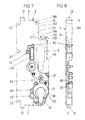
- the upper rear edge of the lock edge of the lock housing 2 forms an approximately angular bulge 106.
- a contour-adapted corner angle 107 located between the lock base 10 and the lock cover 11 limits this bulge toward the rear narrow side of the lock housing.
- the end areas of the corner bracket 107 are with threaded holes 108, 109 provided, which allow the connection to the castle ceiling 11 and the castle floor 10.
- the bulge 106 framed by the corner bracket 107 forms with its rounded inner apex a fitting plate screw through hole 110.
- One leg of the bulge 106 is oriented vertically and runs parallel to the cuff 1, while the other leg is directed at an acute angle to the cuff and extends in the upward direction.
- the depth of the bulge 106 lying in the facing direction extends over the extension of the connecting line L of the nut 97 and the fitting screw passage hole 100, cf. Fig. 1.
- a door equipped with the illustrated espagnolette lock is provided with a long plate 111, shown in phantom in FIG. 1, this can be held by means of three screws 112, 113 and 114.
- the upper fastening screw 112 enters the bulge 106 and thus extends above the nut bearing point.
- the second fastening screw 113 passes through the fitting plate screw passage hole 100 of the bearing housing 98, while the third fastening screw 114 runs below the lock cylinder and the lock housing 2. This measure makes it possible, for example, to only loosen the central fastening screw 113 in order to then be able to remove the espagnolette lock.
- the long plates do not have to be dismantled for this, as is usually the case.
- Another bulge 115 is provided in the area of the lower corner of the lock housing 2. This is formed by the rear contour of the carrier plate 37, which contour the castle ceiling 11 and the castle floor 10 are adapted in the corresponding area.
- the bulge 115 extends rearward of the lock cylinder 41.
- a depth of the bulge 115 is selected such that the bulge bottom 115 'of the lock cylinder longitudinal axis is closer than the distance between the lock cylinder longitudinal axis and the faceplate adjacent through the faceplate screw passage hole 122.
- This having carrier plate 37 forms with its rear narrow side wall the bulge bottom, which runs obliquely towards the cuff 1.
- the depth thereof pointing in the direction of the faceplate is at least so great that the bulge bottom 116 'is closer to the nut center than the distance between the nut center and the fitting screw passage hole adjacent to it, which is adjacent on the faceplate and which is held by the carrier plate 37 is designed as slot 120.
- the two aforementioned bulges 115, 116 allow the door to be assigned rosettes 117, 118 indicated by dash-dotted lines in FIG. 1 instead of the long plates in the area of the nut and the locking cylinder.
- One fastening screw 119 for the rosette 117 passes through the elongated hole 120 of the carrier plate 37, while the other fastening screw 121 penetrates the door in the region of the bulge 116.
- the elongated hole 120 and the bulge 116 also permit the use of differently shaped bearing housings 98 for the nut in order to be able to implement different spacing dimensions between the nut bearing point and the axis of rotation of the cylinder core.
- a fastening screw 122 ' which penetrates the through hole 122 of the carrier plate 37 and a fastening screw 123 which is arranged diametrically thereto and which runs in the region of the bulge 115 serve to hold the rosette 118 surrounding the locking cylinder.
- the support plate 37 with the gear transmission and the change lever arrangement W and the bearing housing 98 represent structural units. If drive rod locks with different backset dimensions are to be created, these structural units need not be modified. Rather, it is sufficient to lengthen or shorten the castle floor and castle ceiling, while the rear area remains unchanged including the bulges. Corresponding reductions and extensions are then to be made for the bolt and the latch and the connecting rod connecting slide 28. Due to this slight change, however, a large range of differently designed locks can be manufactured combined with reduced production costs and reduced storage.
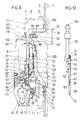
- the latch can be withdrawn in the key withdrawal position when the bolt 35 is closed by actuating the lever handle.
- the nut 97 is pivoted into the position illustrated in FIG. 16 via the pusher (not illustrated). Their tooth 97 'shifts the nut actuating slide 95 in the downward direction.
- the third arm 94 of the deflecting element 84 lying in the movement path of the nut actuating slide is acted upon by pivoting the deflecting element 84 clockwise.
- the second arm 88 forming the latch arm pulls the latch 33 back via the pin / slot connection.
- the change lever spring 80 which also serves as a latch spring, is tensioned.
- the change lever spring 80 guides the deflection member 84 into the starting position by relaxing.
- the change lever operation is shown in Fig. 17.
- the end gear 51 is taken along via the gear transmission, which leads to an upward displacement of the connecting rod connecting slide 28, as a result of the tooth engagement.
- the control edge 76 of the connecting rod connecting slide 28 acts on the end 75 'of the intermediate member 75 in parallel with a pivoting of the actuating arm 71 in the clockwise direction, which pivoting is limited by the hook 72 resting on the support ring shoulder 73.
- the hook 72 and the counter-hook 74 come into contact with one another and entrainment of the actuating arm 71, the pivot pin 70 of which moves upward within the arch slot 69 of the carrier plate 37.
- the intermediate link 75 is carried in the upward direction. Its end portion 78, which forms a tappet, acts on the driving shoulder 87 of the first arm 86 of the deflection element 84. As a result, the deflection element 84 pivots and takes the latch 33 with it in the lock-in direction in the direction of the lock. During this process, the change lever spring 80 is charged. If the key is brought into the key withdrawal position after the door has been opened, the ring gear 39 rotates back by the appropriate amount. At the same time, the change lever spring 80 can relax, pivot the deflection element 84 counterclockwise and drive the latch 33 into its forward position.
- the locking of the bolt 35 requires an opposite closing rotation.
- the drive rod connecting slide 28, 53 are driven in opposite directions by meshing.
- the direction of movement of the connecting rod connecting slides 28, 53 is indicated in FIG. 9 by arrows.
- the drive rods 3, 4 with the locking members 5 attached to them are dragged along.
- the pivot lever 56 does not change its position. This means that the connecting rod connecting slides advance with the connecting rods.
- the extension 65 Shortly before, the extension 65 has also released the locking edge 66 of the locking tail 35 ′′. This is the case after turning a key.
- the locking of the bolt 35 therefore only begins when the door has been sufficiently tightened by the corresponding locking members. Accordingly, the bolt can also dip into its associated striking plate recess without interference.
- the pivoting lever 56 is then rotated via the tooth engagement while simultaneously taking the bolt into the pre-closing position illustrated in FIG. 18.
- the control arm 61 acts on a stop 124 of the carrier plate 37. In this pre-locking position, the key can be removed. Any push-back forces acting on the bolt are directed into the locking cylinder via the tooth engagement.
- the locking of the bolt 35 takes place by means of an opposite closing rotation.
- the drive rod connecting slides 28, 53 are driven in opposite directions in the opposite direction of the arrow via the end wheel 51 and the toothed rack engagement.
- the rack 64 comes out of engagement with the toothing of the pivot lever 56.
- the bolt 35 is closed, since then the rearward displacement is taken over by the extension 65 by the lower, oblique end edge 65 'acting on the run-up slope 57 of the bolt tail 35''and thereby forcing the return movement while taking the bolt 35 at the same time.
- the extension 65 again comes in front of the locking edge 66 of the locking tail 35 ′′.
Priority Applications (2)
| Application Number | Priority Date | Filing Date | Title |
|---|---|---|---|
| EP93116411A EP0581337B1 (fr) | 1990-05-02 | 1991-02-25 | Casemont bolt |
| EP93119160A EP0592012B1 (fr) | 1990-05-02 | 1991-02-25 | Crémone |
Applications Claiming Priority (2)
| Application Number | Priority Date | Filing Date | Title |
|---|---|---|---|
| DE4014042A DE4014042A1 (de) | 1990-05-02 | 1990-05-02 | Treibstangenschloss |
| DE4014042 | 1990-05-02 |
Related Child Applications (2)
| Application Number | Title | Priority Date | Filing Date |
|---|---|---|---|
| EP93116411.5 Division-Into | 1993-10-11 | ||
| EP93119160.5 Division-Into | 1993-11-27 |
Publications (3)
| Publication Number | Publication Date |
|---|---|
| EP0454960A2 true EP0454960A2 (fr) | 1991-11-06 |
| EP0454960A3 EP0454960A3 (en) | 1992-03-04 |
| EP0454960B1 EP0454960B1 (fr) | 1995-12-13 |
Family
ID=6405554
Family Applications (3)
| Application Number | Title | Priority Date | Filing Date |
|---|---|---|---|
| EP93116411A Expired - Lifetime EP0581337B1 (fr) | 1990-05-02 | 1991-02-25 | Casemont bolt |
| EP93119160A Expired - Lifetime EP0592012B1 (fr) | 1990-05-02 | 1991-02-25 | Crémone |
| EP91102728A Expired - Lifetime EP0454960B1 (fr) | 1990-05-02 | 1991-02-25 | Cremone |
Family Applications Before (2)
| Application Number | Title | Priority Date | Filing Date |
|---|---|---|---|
| EP93116411A Expired - Lifetime EP0581337B1 (fr) | 1990-05-02 | 1991-02-25 | Casemont bolt |
| EP93119160A Expired - Lifetime EP0592012B1 (fr) | 1990-05-02 | 1991-02-25 | Crémone |
Country Status (3)
| Country | Link |
|---|---|
| EP (3) | EP0581337B1 (fr) |
| AT (3) | ATE135078T1 (fr) |
| DE (4) | DE4014042A1 (fr) |
Cited By (3)
| Publication number | Priority date | Publication date | Assignee | Title |
|---|---|---|---|---|
| EP0602323A1 (fr) * | 1992-12-16 | 1994-06-22 | Carl Fuhr GmbH & Co. | Serrure avec bielle motrice |
| US5495731A (en) * | 1993-03-26 | 1996-03-05 | Roto Frank Eisenwarenfabrik Aktiengesellschaft | Multiple-bolt door lock |
| US6109666A (en) * | 1998-09-23 | 2000-08-29 | Ferco International, Ferrures Et Serrures De Batiment Sa | Espagnolette or espagnolette-lock for a door, French window or the like |
Families Citing this family (3)
| Publication number | Priority date | Publication date | Assignee | Title |
|---|---|---|---|---|
| DE19512273A1 (de) * | 1995-04-01 | 1996-10-02 | Fliether Karl Gmbh & Co | Schloß mit umwendbarer Falle |
| FR2766865B1 (fr) * | 1997-08-01 | 1999-10-08 | Vachette Sa | Dispositif de fermeture, en particulier serrure avec pene demi-tour, a encastrer dans un battant de porte-fenetre ou analogue |
| AT406403B (de) * | 1998-07-23 | 2000-05-25 | Roto Frank Eisenwaren | Umstellbare falle an einem schloss |
Citations (2)
| Publication number | Priority date | Publication date | Assignee | Title |
|---|---|---|---|---|
| DE2925147A1 (de) * | 1979-06-22 | 1981-01-22 | Siegenia Frank Kg | Tuerschloss, insbesondere fuer haus- und wohnungsabschlusstueren |
| EP0224658A2 (fr) * | 1985-12-05 | 1987-06-10 | Carl Fuhr GmbH & Co. | Serrure à barre coulissante |
Family Cites Families (12)
| Publication number | Priority date | Publication date | Assignee | Title |
|---|---|---|---|---|
| DE115401C (fr) * | ||||
| US1513797A (en) * | 1923-09-08 | 1924-11-04 | Greene Tweed & Co Inc | Door lock |
| FR875232A (fr) * | 1941-05-09 | 1942-09-11 | Serrure | |
| FR1091823A (fr) * | 1953-10-16 | 1955-04-15 | Guerville Riquier Ets | Serrure à pêne demi-tour perfectionné |
| FR2025272A6 (fr) * | 1969-03-08 | 1970-09-04 | Drevet Et Cie | |
| FR2266785A1 (en) * | 1974-04-03 | 1975-10-31 | Ferco Usine Ferrures | Casement bolt for window or door - has half-turn bolt parallel to cranked bridging element |
| FR2346535A1 (fr) * | 1976-04-01 | 1977-10-28 | Fima Sa | Cremone a trois penes pour battant de porte |
| IL51358A (en) * | 1977-01-31 | 1979-07-25 | Zvi Rochmann | Door locking devices of the multiple bolt type |
| DE3505379C2 (de) * | 1985-02-16 | 1996-03-21 | Fliether Karl Gmbh & Co | Treibstangenschloß |
| DE3537786A1 (de) * | 1985-10-24 | 1987-04-30 | Fliether Karl Gmbh & Co | Treibstangenschloss |
| DE4014041A1 (de) * | 1990-05-02 | 1991-11-07 | Fuhr Carl Gmbh & Co | Schliesszylinderbetaetigbares treibstangenschloss |
| DE4014046C2 (de) * | 1990-05-02 | 1998-12-17 | Fuhr Carl Gmbh & Co | Schließzylinderbetätigbares Treibstangenschloß |
-
1990
- 1990-05-02 DE DE4014042A patent/DE4014042A1/de not_active Withdrawn
-
1991
- 1991-02-25 DE DE59107523T patent/DE59107523D1/de not_active Expired - Lifetime
- 1991-02-25 AT AT93119160T patent/ATE135078T1/de not_active IP Right Cessation
- 1991-02-25 DE DE59107395T patent/DE59107395D1/de not_active Expired - Fee Related
- 1991-02-25 AT AT91102728T patent/ATE131568T1/de not_active IP Right Cessation
- 1991-02-25 DE DE59107054T patent/DE59107054D1/de not_active Expired - Lifetime
- 1991-02-25 EP EP93116411A patent/EP0581337B1/fr not_active Expired - Lifetime
- 1991-02-25 EP EP93119160A patent/EP0592012B1/fr not_active Expired - Lifetime
- 1991-02-25 EP EP91102728A patent/EP0454960B1/fr not_active Expired - Lifetime
- 1991-02-25 AT AT93116411T patent/ATE134015T1/de not_active IP Right Cessation
Patent Citations (2)
| Publication number | Priority date | Publication date | Assignee | Title |
|---|---|---|---|---|
| DE2925147A1 (de) * | 1979-06-22 | 1981-01-22 | Siegenia Frank Kg | Tuerschloss, insbesondere fuer haus- und wohnungsabschlusstueren |
| EP0224658A2 (fr) * | 1985-12-05 | 1987-06-10 | Carl Fuhr GmbH & Co. | Serrure à barre coulissante |
Cited By (5)
| Publication number | Priority date | Publication date | Assignee | Title |
|---|---|---|---|---|
| EP0602323A1 (fr) * | 1992-12-16 | 1994-06-22 | Carl Fuhr GmbH & Co. | Serrure avec bielle motrice |
| DE4242523C2 (de) * | 1992-12-16 | 2002-02-14 | Fuhr Carl Gmbh & Co | Treibstangenschloß |
| DE4242523C5 (de) * | 1992-12-16 | 2005-08-25 | Carl Fuhr Gmbh & Co. Kg | Treibstangenschloß |
| US5495731A (en) * | 1993-03-26 | 1996-03-05 | Roto Frank Eisenwarenfabrik Aktiengesellschaft | Multiple-bolt door lock |
| US6109666A (en) * | 1998-09-23 | 2000-08-29 | Ferco International, Ferrures Et Serrures De Batiment Sa | Espagnolette or espagnolette-lock for a door, French window or the like |
Also Published As
| Publication number | Publication date |
|---|---|
| DE59107523D1 (de) | 1996-04-11 |
| EP0581337A2 (fr) | 1994-02-02 |
| EP0581337B1 (fr) | 1996-02-07 |
| ATE131568T1 (de) | 1995-12-15 |
| DE59107395D1 (de) | 1996-03-21 |
| EP0592012B1 (fr) | 1996-03-06 |
| ATE135078T1 (de) | 1996-03-15 |
| EP0592012A1 (fr) | 1994-04-13 |
| DE59107054D1 (de) | 1996-01-25 |
| EP0581337A3 (en) | 1994-06-22 |
| ATE134015T1 (de) | 1996-02-15 |
| EP0454960A3 (en) | 1992-03-04 |
| EP0454960B1 (fr) | 1995-12-13 |
| DE4014042A1 (de) | 1991-11-07 |
Similar Documents
| Publication | Publication Date | Title |
|---|---|---|
| EP0413177B1 (fr) | Serrure pour bielle motrice | |
| DE3505379C2 (de) | Treibstangenschloß | |
| EP0455944B1 (fr) | Serrure de barre coulissante manoeuvrable d'un barillet | |
| EP0454966B1 (fr) | Serrure avec bielle motrice actionnée par cylindre de fermeture | |
| EP0783616A1 (fr) | Fermeture a barre | |
| EP1020597A1 (fr) | Serrure à crémone avec une serrure principal et une serrure complémentaire | |
| EP0454959B1 (fr) | Serrure de barre coulissante manoeuvrable d'un barillet | |
| EP0358971A2 (fr) | Crémone | |
| EP0592012B1 (fr) | Crémone | |
| DE3148030A1 (de) | Zahnradantrieb in einem schliesszylinderbetaetigbaren treibstangenschloss mit schubriegel | |
| EP0454958A1 (fr) | Serrure, notamment serrure avec bielle motrice | |
| EP0454965B1 (fr) | Serrure encatrée notamment avec bielle motrice | |
| DE19815671B4 (de) | Treibstangenverschluß | |
| DE3901957C2 (de) | Treibstangenverschluß, insbesondere für Balkontüren | |
| EP0995865A2 (fr) | Serrure, notamment crémone serrure | |
| DE3427713A1 (de) | Mehrtourig schliessendes treibstangenschloss | |
| DE8532525U1 (de) | Treibstangenschloß mit Schließzylinder | |
| DE4041537A1 (de) | Treibstangenverschluss | |
| DE2845277A1 (de) | Treibstangenschloss mit falle | |
| EP0602323B1 (fr) | Serrure avec bielle motrice | |
| DE4302920A1 (de) | Schloß, insbesondere Einsteckschloß | |
| DE8210306U1 (de) | Treibstangenschloß mit Schließzylinder | |
| DE3807338A1 (de) | Schloss, insbesondere einsteckschloss | |
| DE2105794A1 (de) | Einsteckschloß für Badezellentüren oder dergleichen | |
| CH691983A5 (de) | Treibstangenschloss. |
Legal Events
| Date | Code | Title | Description |
|---|---|---|---|
| PUAI | Public reference made under article 153(3) epc to a published international application that has entered the european phase |
Free format text: ORIGINAL CODE: 0009012 |
|
| AK | Designated contracting states |
Kind code of ref document: A2 Designated state(s): AT DE FR GB IT |
|
| PUAL | Search report despatched |
Free format text: ORIGINAL CODE: 0009013 |
|
| AK | Designated contracting states |
Kind code of ref document: A3 Designated state(s): AT DE FR GB IT |
|
| 17P | Request for examination filed |
Effective date: 19920226 |
|
| 17Q | First examination report despatched |
Effective date: 19930518 |
|
| GRAA | (expected) grant |
Free format text: ORIGINAL CODE: 0009210 |
|
| AK | Designated contracting states |
Kind code of ref document: B1 Designated state(s): AT DE FR GB IT |
|
| REF | Corresponds to: |
Ref document number: 131568 Country of ref document: AT Date of ref document: 19951215 Kind code of ref document: T |
|
| XX | Miscellaneous (additional remarks) |
Free format text: TEILANMELDUNG 93116411.5 EINGEREICHT AM 25/02/91. |
|
| GBT | Gb: translation of ep patent filed (gb section 77(6)(a)/1977) |
Effective date: 19951213 |
|
| REF | Corresponds to: |
Ref document number: 59107054 Country of ref document: DE Date of ref document: 19960125 |
|
| ET | Fr: translation filed | ||
| ITF | It: translation for a ep patent filed |
Owner name: STUDIO JAUMANN |
|
| PLBE | No opposition filed within time limit |
Free format text: ORIGINAL CODE: 0009261 |
|
| STAA | Information on the status of an ep patent application or granted ep patent |
Free format text: STATUS: NO OPPOSITION FILED WITHIN TIME LIMIT |
|
| 26N | No opposition filed | ||
| REG | Reference to a national code |
Ref country code: GB Ref legal event code: IF02 |
|
| PG25 | Lapsed in a contracting state [announced via postgrant information from national office to epo] |
Ref country code: IT Free format text: LAPSE BECAUSE OF NON-PAYMENT OF DUE FEES;WARNING: LAPSES OF ITALIAN PATENTS WITH EFFECTIVE DATE BEFORE 2007 MAY HAVE OCCURRED AT ANY TIME BEFORE 2007. THE CORRECT EFFECTIVE DATE MAY BE DIFFERENT FROM THE ONE RECORDED. Effective date: 20050225 |
|
| PGFP | Annual fee paid to national office [announced via postgrant information from national office to epo] |
Ref country code: FR Payment date: 20060206 Year of fee payment: 16 |
|
| PGFP | Annual fee paid to national office [announced via postgrant information from national office to epo] |
Ref country code: AT Payment date: 20060209 Year of fee payment: 16 |
|
| PGFP | Annual fee paid to national office [announced via postgrant information from national office to epo] |
Ref country code: GB Payment date: 20060213 Year of fee payment: 16 |
|
| GBPC | Gb: european patent ceased through non-payment of renewal fee |
Effective date: 20070225 |
|
| PG25 | Lapsed in a contracting state [announced via postgrant information from national office to epo] |
Ref country code: AT Free format text: LAPSE BECAUSE OF NON-PAYMENT OF DUE FEES Effective date: 20070225 |
|
| REG | Reference to a national code |
Ref country code: FR Ref legal event code: ST Effective date: 20071030 |
|
| PG25 | Lapsed in a contracting state [announced via postgrant information from national office to epo] |
Ref country code: GB Free format text: LAPSE BECAUSE OF NON-PAYMENT OF DUE FEES Effective date: 20070225 Ref country code: FR Free format text: LAPSE BECAUSE OF NON-PAYMENT OF DUE FEES Effective date: 20070228 |
|
| PGFP | Annual fee paid to national office [announced via postgrant information from national office to epo] |
Ref country code: DE Payment date: 20100204 Year of fee payment: 20 |
|
| REG | Reference to a national code |
Ref country code: DE Ref legal event code: R071 Ref document number: 59107054 Country of ref document: DE |
|
| PG25 | Lapsed in a contracting state [announced via postgrant information from national office to epo] |
Ref country code: DE Free format text: LAPSE BECAUSE OF EXPIRATION OF PROTECTION Effective date: 20110225 |