EP0454445B1 - Wellenformentzerrer mit Neuronalnetzwerk - Google Patents
Wellenformentzerrer mit Neuronalnetzwerk Download PDFInfo
- Publication number
- EP0454445B1 EP0454445B1 EP91303700A EP91303700A EP0454445B1 EP 0454445 B1 EP0454445 B1 EP 0454445B1 EP 91303700 A EP91303700 A EP 91303700A EP 91303700 A EP91303700 A EP 91303700A EP 0454445 B1 EP0454445 B1 EP 0454445B1
- Authority
- EP
- European Patent Office
- Prior art keywords
- neural network
- equalization
- detection
- network
- distortion
- Prior art date
- Legal status (The legal status is an assumption and is not a legal conclusion. Google has not performed a legal analysis and makes no representation as to the accuracy of the status listed.)
- Expired - Lifetime
Links
Images


Classifications
-
- H—ELECTRICITY
- H04—ELECTRIC COMMUNICATION TECHNIQUE
- H04L—TRANSMISSION OF DIGITAL INFORMATION, e.g. TELEGRAPHIC COMMUNICATION
- H04L25/00—Baseband systems
- H04L25/02—Details ; arrangements for supplying electrical power along data transmission lines
- H04L25/03—Shaping networks in transmitter or receiver, e.g. adaptive shaping networks
- H04L25/03006—Arrangements for removing intersymbol interference
- H04L25/03165—Arrangements for removing intersymbol interference using neural networks
-
- G—PHYSICS
- G06—COMPUTING OR CALCULATING; COUNTING
- G06N—COMPUTING ARRANGEMENTS BASED ON SPECIFIC COMPUTATIONAL MODELS
- G06N3/00—Computing arrangements based on biological models
- G06N3/02—Neural networks
- G06N3/04—Architecture, e.g. interconnection topology
-
- G—PHYSICS
- G06—COMPUTING OR CALCULATING; COUNTING
- G06N—COMPUTING ARRANGEMENTS BASED ON SPECIFIC COMPUTATIONAL MODELS
- G06N3/00—Computing arrangements based on biological models
- G06N3/02—Neural networks
- G06N3/04—Architecture, e.g. interconnection topology
- G06N3/044—Recurrent networks, e.g. Hopfield networks
- G06N3/0442—Recurrent networks, e.g. Hopfield networks characterised by memory or gating, e.g. long short-term memory [LSTM] or gated recurrent units [GRU]
-
- G—PHYSICS
- G06—COMPUTING OR CALCULATING; COUNTING
- G06N—COMPUTING ARRANGEMENTS BASED ON SPECIFIC COMPUTATIONAL MODELS
- G06N3/00—Computing arrangements based on biological models
- G06N3/02—Neural networks
- G06N3/04—Architecture, e.g. interconnection topology
- G06N3/0499—Feedforward networks
-
- G—PHYSICS
- G06—COMPUTING OR CALCULATING; COUNTING
- G06N—COMPUTING ARRANGEMENTS BASED ON SPECIFIC COMPUTATIONAL MODELS
- G06N3/00—Computing arrangements based on biological models
- G06N3/02—Neural networks
- G06N3/08—Learning methods
- G06N3/09—Supervised learning
-
- H—ELECTRICITY
- H04—ELECTRIC COMMUNICATION TECHNIQUE
- H04L—TRANSMISSION OF DIGITAL INFORMATION, e.g. TELEGRAPHIC COMMUNICATION
- H04L25/00—Baseband systems
- H04L25/02—Details ; arrangements for supplying electrical power along data transmission lines
- H04L25/03—Shaping networks in transmitter or receiver, e.g. adaptive shaping networks
- H04L25/03006—Arrangements for removing intersymbol interference
- H04L2025/03433—Arrangements for removing intersymbol interference characterised by equaliser structure
- H04L2025/03439—Fixed structures
- H04L2025/03445—Time domain
- H04L2025/03464—Neural networks
Definitions
- the present invention relates to a waveform equalizer using a neural network, and a system for supervising and controlling the equalizer.
- signals suffer distortion in their waveforms during transmission thereof, and highly precise equalization of the signals is required when the signals are received to prevent an error.
- the distortion is often non-linear.
- the distortion may vary time-dependently. Since the Baud rate in recent data communication is increasing, a very high speed response is required to eliminate the distortion.
- a waveform equalizer is required to adaptively respond to time-dependently varying distortion including non-linear distortion in a waveform of a received signal with very high speed, to realise a highly precise equalization of the signal.
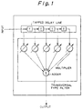
- FIG. 1 shows a typical construction of a transversal type adaptive filter which is conventionally used for equalizing waveforms of received signals.
- the transversal type adaptive filter comprises: a tapped delay line holding a time series of data which is sampled from a received signal which is to be equalized; adaptive multipliers which multiply the time series of data by respective weight coefficients; and an adder which calculates a sum of the outputs of the multipliers.
- the weight coefficients are adaptively determined to realize an equalization of the received signal.
- the waveform equalizer using the transversal type adaptive filter cannot eliminate the non-linear distortion in the received signal.
- An object of the present invention is to provide a waveform equalizer which can adaptively respond to time-dependently varying distortion including non-linear distortion in a waveform of a received signal, and can realize high speed, highly precise equalization of the signal.
- a waveform equalizer for equalizing a distorted signal comprises:
- a distortion characteristic detector for detecting a distortion characteristic of a distorted signal comprises:
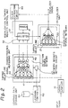
- FIG. 2 is a diagram showing the construction of the first embodiment of the present invention.
- reference numeral 10 denotes a signal sampler unit
- 20 denotes an equalizer unit
- 21 and 41 each denote a tapped delay line
- 22 denotes an equalization neural network
- 30 denotes an equalization network weights control unit
- 31 denotes an equalization network weights storage
- 32 denotes an equalization network weights selector
- 40 denotes a signal characteristics measuring unit
- 42 denotes a detection neural network
- 43 denotes a network weights setting circuit
- 50 denotes a learning controller
- 60 denotes a learning data storage unit
- 80 denotes a clock extracting circuit.
- an input signal which may include distortion and is to be equalized is sampled at a predetermined rate.
- the input signal which may contain distortion may be referred to as a distorted signal.
- the sampled level of the input signal is serially supplied to the tapped delay line 21 in the equalizer unit 20, and the tapped delay line 41 in the signal characteristics measuring unit 40.
- the tapped delay lines 21 and 41 respectively realize the aforementioned time series generating unit, and serially successively receive the sampled levels and outputs in parallel a predetermined number (five in Fig. 2) of the sampled levels which have been last received, to the equalization neural network 22 and the detection neural network 42, respectively.
- Figure 3 is a block diagram showing input-output connections between input layer units and hidden layer units, and between the hidden layer units and the output layer units in a three layer unit neural network.
- Each of the equalization neural network 22 and the detection neural network 42 has a construction, for example, as shown in Fig. 3.
- the input layer units in each of the equalization neural network 22 and the detection neural network 42 receive the outputs of the corresponding tapped delay line 21 or 41, each of the hidden layer units inputs the values received at a predetermined combination of the input layer units and outputs a value which is a function of the inputs thereof, and each of the output layer units inputs the outputs of a predetermined combination of the hidden layer units and outputs a value which is a function of the inputs thereof.
- the network weights W ih and W ji are respectively set in the hidden layer units and the output layer units, and each of the hidden layer units and the output layer unit comprises a linear combination unit for obtaining a linear combination of the inputs thereof using the set of the equalization network weights W ih and W ji , and a non-linear function unit for obtaining a non-linear function of the linear combination.
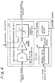
- Each of the hidden layer units and the output layer unit in the neural network can be realized by an analog neuroprocessor, for example, as shown in Fig. 4.
- the analog neuroprocessor of Fig. 4 comprises an analog data processing block 101, a weight data loading block 102, and a control block 103.
- the analog data processing block 101 comprises a multiplying digital to analog converter 104, an adder 105, and a Sigmoid function converter 106.
- the above-mentioned (equalization or detection) network weights are supplied to the multiplying digital to analog converter 104 through the weight data loading block 102.
- the analog input signals are all or a part of the parallel outputs of tapped delay line 21 or 41 in the equalizer unit 20 and the tapped delay line 41 in the signal characteristics measuring unit 40.
- the network weights W i1 , W i2 , ... W in are serially supplied to the multiplying digital to analog converter 104 in the analog neuroprocessor which is used for a hidden layer unit 1′-h, and analog input signals yph corresponding to the network weights W i1 , W i2 , ...
- W in are serially supplied to the multiplying digital to analog converter 104 so that the inputs of the analog input signals yph respectively coincide with the inputs of the corresponding network weights W i1 , W i2 , ... W in .
- the multiplying digital to analog converter 104 serially outputs an analog signal having an amplitude y ph ⁇ W ih which is proportional to the multiplication of respective pairs of amplitudes of the above analog input signals and the corresponding network weights.
- the adder 105 serially receives the above analog output signals from the multiplying digital to analog converter 104, and accumulates the received signals to obtain a signal having an amplitude which is proportional to the linear combination ⁇ y ph ⁇ W ih .
- the Sigmoid function converter 106 transforms the output of the adder 105 in accordance with the Sigmoid function.
- the Sigmoid function is a non-linear function which is continuous and has a gradient equal to or more than zero.
- the analog output of the Sigmoid function converter 106 is output from the analog processing unit 101 of the analog neuroprocessor of Fig. 4, under the control of the control block 103.
- Figure 5 is a block diagram of an example of a three layer unit neural network using the analog neuroprocessors.
- reference numeral 111 denotes an input bus
- 112 to 114, and 119 to 121 each denote a static RAM
- 115 to 117 each denote an analog neuroprocessor for a hidden layer unit
- 118 denotes an intermediate bus
- 122 to 124 each denote an analog neuroprocessor for an output layer unit
- 125 denotes an output layer unit.
- the static RAMs 112 to 114 and 119 to 121 are respectively provided for the analog neuroprocessors 115 to 117 and 122 to 124, to hold the network weights therein and supply the network weights to the corresponding analog neuroprocessors.
- the transfer of the outputs from the tapped delay line 21 or 41 to the respective analog neuroprocessors 115 to 117 in the hidden layer through the input bus 111; the transfer of the outputs from the analog neuroprocessors 115 to 117 in the hidden layer to the respective analog neuroprocessors 122 to 124 in the output layer through the intermediate bus 118; and the transfer of the outputs of the analog neuroprocessors 122 to 124 in the output layer, are respectively carried out in a time sharing manner. It is known that a transformation including a non-linear transformation can be realized by a neural network as above.
- the analog neuroprocessor is commercially available as a semi-conductor chip from Fujitsu Limited.
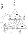
- a recurrent network may be used instead of the hierarchical network as shown in Figure 6 as an example.
- the recurrent network is disclosed in "Encoding Sequential Structure in Simple Recurrent Networks" by Servan-Schreiber, Axel Cleeremans, and James L. McClelland, CMU Technical Report CMU-CU-88-183, 1988. It is known that recurrent networks may be treated as equivalent to hierarchical networks.
- the equalization neural network 22 receives the outputs of the time series generating unit, and equalizes the distorted signal to generate an equalized signal, based on the outputs of the tapped delay line 21 using a set of equalization network weights which are preset therein. That is, the equalizer unit 20 containing the equalization neural network 22 operates as a waveform equalizer for the above-mentioned distorted signal when an optimum bet of the equalization network weights are set therein an explained later.
- the signal characteristics measuring unit 40 detects distortion characteristics of the distorted signal when an optimum set of the detection network weights are set therein as explained later.
- the detection neural network 42 has three outputs, which respectively output values indicating an amplitude distortion, a delay distortion, and a phase distortion, in this example.
- the equalization network weights storage 31 holds a plurality of optimum sets of equalization network weights corresponding to a plurality of possible distortion characteristics, each for being set in the equalization neural network 22, and the equalization network weights selector 32 selects one of the plurality of sets of equalization network weights according to the distortion characteristic (actually, a combination of the amplitude distortion, the delay distortion, and the phase distortion), which is detected in the distortion characteristic measuring unit 40, and supplies the selected set to the equalization neural network 22 to set the selected set therein.
- the equalization network weights selector 32 comprises a writing control circuit for the SRAMs as shown in Fig. 5 in the equalization neural network 22.
- the equalization network weights selector 32 comprises a reading/writing control circuit for the RAM, and the output of the detection neural network 42 is used as an address signal for reading the content of the RAM.
- the clock extracting unit 80 extracts a clock (timing) signal from the output (equalized) signal of the equalization unit 20. The clock signal is supplied to the equalization network weights selector 32 to provide a timing of the selection.
- the learning controller 50 obtains an optimum set of the equalization network weights for each distortion characteristic (each combination of values of the amplitude distortion, the delay distortion, and the phase distortion) so that the equalization neural network 22 outputs a best equalized signal for a distorted signal having the distortion characteristic when the optimum set of the equalization network weights is preset in the equalization neural network 22, and supplies the obtained set to the equalization network weights storage 31 so that the equalization network storage 31 stores therein the set of equalization network weights obtained for each of the distortion characteristics (each of the combinations of values of the amplitude distortions, the delay distortions, and the phase distortions).
- the equalization network weights storage 31 is a RAM, the above obtained set of the equalization network weights is written in the RAM through the above reading/writing control circuit.
- the above functions of the learning controller 50 for obtaining and supplying the optimum set of the equalization network weights through following units is realized by a software program which contains the following units:
- the above operation may be carried out by using a simulated equalization neural network unit instead of the above real equalization neural network 22.
- the simulated equalization neural network unit (by a software) receives the above model distorted signals to the equalization neural network unit, and simulates the operation of the equalization neural network 22.
- the learning controller 50 obtains an optimum set of the detection network weights which is common to all distortion characteristics (all combinations of values of the amplitude distortions, the delay distortions, and the phase distortions) so that the detection neural network 42 outputs the distortion characteristics corresponding to the distorted signals when the distorted signals after sampled by the signal sampler 10, are received by the signal characteristics measuring unit 40 when the obtained set is preset to the detection neural network 42; and presets the obtained set to the detection neural network 42.
- the above functions of the learning controller 50 for obtaining and supplying the optimum set of the detection network weights is realized by a software program which contains the following units:
- Any distortion including non-linear distortion can be detected as distortion values by using the neural network 42.
- the above operation may be carried out by using a simulated detection neural network unit instead of the above real detection neural network 42.
- the simulated detection neural network unit (by software) receives the above model distorted signals which are to be applied to the detection neural network 42, and simulates the operation of the detection neural network 42.
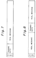
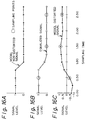
- Figures 7 and 8 are diagrams showing an example of a frame format of the input signal.
- a predetermined training data is included after a synchronization pattern SYNC, and before a real message.
- a predetermined training data is inserted intervening the real message.
- the training data is the same data as the aforementioned model distorted signal which is used for obtaining the optimum set of the detection network weights.
- the detection neural network 42 After each frame is received and sampled in the signal sampler unit 10, the sampled training data is supplied through the tapped delay line 41 to the detection neural network 42. Receiving the training data signal, the detection neural network 42 outputs the values of the amplitude distortion, the delay distortion, and the phase distortion from the three output layer units thereof.
- the equalization neural network 22 eliminates the above distortion from its input signal when the set of the equalization network weights corresponding to the distortion characteristics is set thereto. Therefore, when the real message portion of the above frame is supplied through the tapped delay line 21 to the equalization neural network 22, the real message portion of the above frame is equalized. As mentioned before, any distortion including non-linear distortion can be eliminated by using the neural network 22.
- each frame of the distorted signal sampled in the sampler unit 10 is once held in a buffer memory (not shown), and then the training data portion in the frame is first read from the buffer memory to be supplied to the detection neural network 42 as explained above, and the distortion characteristic values are determined from the distortion in the training data portion at the outputs of the detection neural network 42. Then, a set of equalization network weights corresponding to the combination of the supplied distortion characteristic values, are set in the equalization neural network 22. After that, the real message portion of the above frame is read out of the buffer memory to be supplied through the tapped delay line 21 to the equalization neural network 22, and the real message portion of the above frame is equalized.
- the training data portion can be first supplied to the signal characteristics measuring unit 40 before the real massage portion is supplied to the equalization unit 20 even when the frame format of Fig. 8 is used.
- the frame format of Fig. 8 is advantageous because the maximum time difference from the training data portion to the farthest portion of the real message portion in each frame in Fig. 8 is smaller than Fig. 7, and therefore, the maximum difference of the distortion characteristic in the training data portion and the real message portion in Fig. 8 is smaller than Fig. 7.
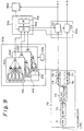
- Figure 9 is a diagram showing the construction of the second embodiment of the present invention.
- Fig. 9 shows the construction of the demodulation and equalization apparatus for demodulating and equalizing a received signal which is modulated by the quadrature phase shift keying (QPSK) by delay detection.
- QPSK quadrature phase shift keying
- reference numeral 20a denotes an equalizer unit, 23 and 24 each denote an equalizer, 30a denotes an equalization network weights control unit, 31a denotes an equalization network weights storage, 32a denotes an equalization network weights selector, 40a denotes a signal characteristics measuring unit, 41a, 41a′ and 41a ⁇ each denote a tapped delay line, 42a, 42a′ and 42a ⁇ each denote a detection neural network, 43 denotes a network weights setting circuit, 70 denotes a demodulator unit, 71 denotes an band pass filter, 72 denotes a limiter, 73 denotes a delay detection circuit, 74 and 76 each denote a low pass filter, 75 and 77 each denote an analog to digital converter, and 80a denotes a clock extracting circuit.
- the frequency range of the received signal which is modulated by the quadrature phase shift deying (QPSK) is limited the carrier frequency of the modulated signal by the band pass filter 71. Then, the output signal of the band pass filter 71 is transformed to a rectangular form by the limiter 72, and the I-channel and the Q-channel of the received signal is obtained by the delay detection circuit 73. The I-channel and the Q-channel are then sampled and converted to digital forms in the analog to digital converters 75 and 77 after the higher harmonic components are eliminated by the low pass filters 74 and 76, respectively. The digital sampled signals of the I-channel and the Q-channel are supplied to first and second equalization units 23 and 24, respectively. In addition, the I-channel signal is supplied to the signal characteristics measuring unit 40a.
- QPSK quadrature phase shift deying
- the existence of the limiter 72 and the delay detection circuit 73 will cause a non-linear distortion in the received signal.
- the signal characteristics measuring unit 40a comprises a plurality of detection neural network units 42a, 42a′ and 42a ⁇ which respectively receive the outputs of the tapped delay lines 41a, 41a′ and 41a ⁇ in the distortion characteristic detecting unit 40a, and generate a value indicating one of the distortion characteristics of the distorted signal based on the outputs of the corresponding one of the tapped delay lines 41a, 41a′ and 41a ⁇ using a set of detection network weights which are preset therein.
- the set of the detection network weights are determined and preset in a similar way to the first embodiment, although the learning controller 50 is not shown in Fig. 9.
- each of the plurality of detection neural network units 42a, 42a′ and 42a ⁇ outputs one of the above distortion characteristics, the amplitude distortion, the delay distortion, and the phase distortion.
- each of the plurality of detection neural network units 42a, 42a′ and 42a ⁇ outputs one of the above distortion characteristics, the amplitude distortion, the delay distortion, and the phase distortion.
- only one tapped delay line may be provided commonly to the plurality of detection neural network units 42a, 42a′ and 42a ⁇ .
- the equalization network weights storage 31a stores all the optimum sets of the equalization network weights which are to be set in the first and second equalization units 23 and 24, where the optimum sets are determined by the learning controller 50, and are stored by the equalization network weights storage 32a as in the first embodiment.
- the equalization network weights selector 32a receives the above outputs of the plurality of detection neural network units 42a, 42a′ and 42a ⁇ , and reads and sets one of the plurality of sets of the equalization network weights in the first and second equalization units 23 and 24. Therefore, the above I-channel and the Q-channel signals are respectively equalized through the first and second equalization units 23 and 24.
- the clock extracting unit 80a extracts a timing signal (clock) from the equalized I-channel signal to supply a timing of its operation.
- the function of the delay detection in the demodulation unit 70 may be included in the equalization unit 20a. That is, the first and second equalization units 23 and 24 each can operate as a demodulator at the same time as an equalizer.
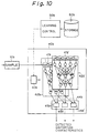
- FIG. 10 is a diagram showing the construction of the third embodiment of the present invention.
- Fig. 10 shows the construction of the signal characteristics measuring unit 40b in the third embodiment of the present invention.
- reference numeral 10b denotes a signal sampler unit
- 40b denotes a signal characteristics measuring unit
- 41b and 41b′ each denote a tapped delay line
- 42b and 42b′ each denote a detection neural network
- 43b denotes a network weights setting circuit
- 44b denotes a zone selector unit
- 45b and 45b′ each denote a range selector unit.
- the signal characteristics measuring unit 40b comprises a plurality of detection neural networks 42b and 42b′.
- Each of the plurality of detection neural networks 42b and 42b′ receives the outputs of the tapped delay lines 41b and 41b′ in the distortion characteristic detecting unit 40b, generates and outputs values respectively indicating the distortion characteristics (the amplitude distortion, the delay distortion, and the phase distortion) of the distorted signal, when each of the amounts of the distortion characteristics which are contained in the distorted signal, is within a part, which is assigned to the detection neural network, of the whole range of the distortion characteristic to be detected, and generates and outputs a predetermined value (for example, the maximum value of the output range of the detection neural network units 42b and 42b′) when an amount of the detection characteristic which is contained in the distorted signal, is out of the part assigned to the detection neural network, based on the outputs of the tapped delay line in the signal characteristics measuring unit 40b using a set of detection network weights which are preset therein.
- each of the plurality of detection neural network units 42b and 42b′ outputs a value indicating one of the above distortion characteristics, the amplitude distortion, the delay distortion, and the phase distortion.
- each of the plurality of detection neural network units 42b and 42b′ outputs a value indicating one of the above distortion characteristics, the amplitude distortion, the delay distortion, and the phase distortion.
- only one tapped delay line may be provided commonly to the plurality of detection neural network units 42b and 42b′.
- the plurality of range selector units 45b and 45b′ are each provided for one of the distortion characteristics (for example, the amplitude distortion) which are detected by the signal characteristics measuring unit 40b.
- Each of the plurality of range selector units 45b and 45b′ receives the outputs of the plurality of detection neural network units 42b and 42b′ regarding one of the of distortion characteristics, and selects the output of one of the plurality of detection neural network units 42b and 42b′.
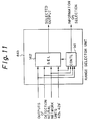
- Figure 11 is a diagram showing the construction of each of the plurality of range selector units 45b and 45b′. As shown in Fig. 11, each range selector unit comprise a selector 142 and a selector controller 141.
- the selector controller 141 in each range selector unit receives the outputs of the plurality of detection neural network units 42b and 42b′ regarding the corresponding one of the distortion characteristics, and then controls the corresponding selector 142 based on the received outputs of the plurality of detection neural network units 42b and 42b′, so that the corresponding selector selects the output of one of the detection neural network units 42b and 42b′ which does not output the predetermined value, and outputs the above predetermined value (for example, the maximum value of the output range of the detection neural network units 42b and 42b′) when all of the outputs of the detection neural network units 42b and 42b′ regarding the corresponding one of the distortion characteristics are equal to the predetermined value (the maximum value).
- the predetermined value for example, the maximum value of the output range of the detection neural network units 42b and 42b′
- the above selector controller 141 sends information on the above selection to the equalization network weights storage 32b in the equalization network weights control unit 30b. Receiving the information together with the output of the selector 141, the equalization network weights storage 32b can recognize the real amount of the distortion characteristic, and select and read the corresponding optimum set of the network weights.
- Figure 12 is a diagram showing the construction of the fourth embodiment of the present invention.
- Fig. 12 shows the construction of the signal characteristics measuring unit 40c in the fourth embodiment of the present invention.
- reference numeral 40c denotes a signal characteristics measuring unit
- 41c-1 to 41c-4 each denote a tapped delay line
- 42c-1 to 42c-4 each denote a detection neural network
- 43c denotes a network weights setting circuit
- 44c denotes a zone selector unit.
- the signal characteristics measuring unit 40c detects only two distortion characteristics, the amplitude distortion and the delay distortion.
- the signal characteristics measuring unit 40c comprises a plurality of detection neural networks 42c-1 to 42c-4.
- Each of the plurality of detection neural networks 42c-1 to 42c-4 receives the outputs of the tapped delay lines 41c-1 to 41c-4 in the distortion characteristic detecting unit 40c, generates and outputs a value respectively indicating a distortion characteristic (the amplitude distortion, the delay distortion, and the phase distortion) of the distorted signal, when an amount of the distortion characteristic which is contained in the distorted signal, is within a part, which is assigned to the detection neural network, of the whole range of the distortion characteristic to be detected, and generates and outputs a predetermined value (for example, the maximum value of the output range of the detection neural network units 42c-1 to 42c-4) when the amount of the distortion characteristic is out of the part assigned to the detection neural network, based on the outputs of the tapped delay line in the signal characteristics measuring unit 40c using a set of detection network weights which are preset therein.
- a predetermined value for example, the maximum value
- the detection neural network 42c-1 outputs a value indicating the amplitude distortion when the amplitude distortion to be detected is not more than the center value of the total range of the amplitude distortion to be detected, and outputs the maximum value of the output range of the detection neural network 42c-1 when the amount of the amplitude distortion which is contained in the distorted signal, is more than the center value of the total range of the amplitude distortion to be detected.
- the detection neural network 42c-2 outputs the value indicating the amplitude distortion when the amount of the amplitude distortion which is contained in the distorted signal, is not less than the center value of the total range of the amplitude distortion to be detected, and outputs the maximum value of the output range of the detection neural network 42c-2 when the amount of the amplitude distortion is less than the center value of the total range of the amplitude distortion to be detected.
- the detection neural network 42c-3 outputs the value indicating the delay distortion when the amount of the delay distortion is not more than the center value of the total range of the delay distortion to be detected, and outputs the maximum value of the output range of the detection neural network 42c-3 when the amount of the delay distortion is more than the center value of the total range of the delay distortion to be detected.
- the detection neural network 42c-4 outputs the value indicating the delay distortion when the amount of the delay distortion is not less than the center value of the total range of the delay distortion to be detected, and outputs the maximum value of the output range of the detection neural network 42c-4 when the amount of the delay distortion is less than the center value of the total range of the delay distortion to be detected. Therefore, each of the above values respectively indicating the amplitude distortion and the delay distortion can be output in the output range substantially twice the output range as the total ranges of the amplitude distortion or the delay distortion is output from one detection neural network.
- the zone selector unit 45c has the same construction as the above-mentioned third embodiment except that only two distortion characteristics are shown in the fourth embodiment.
- Table 1 Range Assignment for Amplitude Distortion and Delay Distortion Amplitude Ratio Delay 0.1 0.2 0.3 0.4 0.5 0.6 0.7 0.8 0.9 1.0 0.1 A A A A A C C C C C 0.2 A A A A A C C C C C 0.3 A A A A A C C C C C 0.4 A A A A A C C C C 0.5 A A A A A A A C C C C C C 0.6 B B B B D D D D D D 0.7 B B B B B D D D D D D D D 0.8 B B B B B B D D D D D D D 0.9 B B B B B D D D D D D 1.0 B B B B B B D D D D D D D D D D Table 2 Example of Output Values Indicating Delay Distortions in a Detection Neural Network Unit Amplitude Ratio Delay 0.1
- Table 1 shows the range assignment for the amplitude distortion and the delay distortion, where the range 0 to 1.0 is assigned to each of the detection neural network units 42c-1 to 42c-4.
- A, B, C, and D each denote a zone which is determined by a combination of the ranges of the amplitude distortion and the delay distortion.
- each of the above values respectively indicating the amplitude distortion and the delay distortion can be output in the output range substantially twice the output range as the total ranges of the amplitude distortion or the delay distortion is output from one detection neural network.
- the set of the detection network weights are determined and preset in a similar way to the first embodiment, although the learning controller 50 is not shown in Fig. 12. Further, instead of providing the plurality of tapped delay lines 41c-1 to 41c-4 for the plurality of detection neural network units 42c-1 to 42c-4, only one tapped delay line may be provided commonly to the plurality of detection neural network units 42c-1 to 42c-4.
- the whole output range of each detection neural network is used for indicating only a part of the total range of the value of a distortion characteristic, so the precision of the distortion characteristics is improved.
- the aforementioned model distorted signals each having a certain distortion characteristic are generated based on a two-wave interference model of a signal on a transmission line.
- a signal which is received at the receiver is approximated by a superimposition of a direct non-distorted wave and a reflected wave which contains distortion such as an amplitude distortion, a delay distortion, and a phase distortion.
- a modulated signal i.e., I(t)coswct + Q(t)sinwct is transmitted from a sender side
- the reflected wave in the I-channel is expressed as A ⁇ (I(t- ⁇ )cos ⁇ c (t- ⁇ ) + Q(t- ⁇ )sin ⁇ c (t- ⁇ )), where A denotes the amplitude distortion, ⁇ denotes the delay distortion which is normalized as 0 ⁇ ⁇ ⁇ 1, and ⁇ denotes the phase distortion which is normalized as 0 ⁇ ⁇ ⁇ 1.
- a predetermined successive data pattern for example, "010” is received on the I-channel, waveforms of demodulated signals (corresponding to the input of the equalization unit 20 of Fig. 2) corresponding to the reception of the pattern "010” which contain distortion corresponding to various values for the amplitude distortion A, the delay distortion ⁇ , and the phase distortion ⁇ , are generated by computer simulations, and the waveforms of the portion "10" in the above pattern "010” is extracted for use as learning signals (the model distorted signals).
- the first bit “0” is provided only for stabilizing the waveforms corresponding to the following bits "10", and therefore, is discarded after the above simulation.
- the above pattern "10" with the preceding bit "0” is predetermined to be the same as the aforementioned training data, i.e., the training data also contains the pattern "010".
- Figure 13 is a diagram showing waveforms of the non-distorted signal corresponding to the pattern "10" and an example of a model distorted signal corresponding to the non-distorted signal
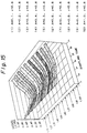
- Figures 14 and 15 are each a diagram showing the waveforms of the distorted signals which are obtained as above for the data pattern "10" and the various combinations of values of the amplitude distortions A and the delay distortions ⁇ .
- the value of the amplitude distortion A is varied from 0.1 to 0.9, and the value of the delay distortion ⁇ is fixed to 0.8. It is assumed that the signal levels are inverted through the demodulation in the simulations.
- seven samples of signal levels are shown for each simulation case, where the sampling rate is four times the Baud rate of the signal.
- the waveform data and the corresponding combinations of the distortion characteristic values are stored in the learning data storage unit 60 (Fig. 2).
- the model simulated signals have been prepared.
- the index p is used for indicating different input signals (corresponding to different model distorted signals containing different distortion characteristics)
- h is used for different input layer units
- i is used for different hidden layer units
- j is used for indicating generally different output layer units (although only one output layer unit is shown in Fig. 3).
- ⁇ and ⁇ each denote a constant, and t denotes a number of learning cycles.
- ⁇ pi y pi ⁇ (1-y pi ).
- ⁇ pj .W ji (t-1) is calculated.
- a correction of the network weight between the input layer and the hidden layer is calculated as
- the above operation back propagation method can be used for obtaining both the equalization network weights and the detection network weights.
- the learning controller 50 presets the above-obtained optimum network weights in the detection neural network.
- the neural network is realized by software using a digital signal processor
- the obtained network weights are stored in a predetermined region of a RAM which is used by the digital signal processor.
- the learning controller 50 obtains the optimum set of the equalization network weights for each of the plurality of model distorted signals, and stores the obtained set in the equalization network weights storage 32 for each distortion characteristic corresponding to the model distorted signal.
- the signal characteristics measuring units 40, 40a, and 40b in which the optimum sets of the network weights are preset, respectively output the values of the distortion characteristics which the distorted training signal contain, as explained before.
- Tables 3 and 4 show results of simulations which have been carried out for verifying the credibility of the signal characteristics measuring unit 40c in Fig. 11.
- the simulations are carried out for smaller and larger ranges of the amplitude distortion and the delay distortion.
- Table 3 shows the possibility of the outputs for the delay distortion t with an error not more than 0.05%
- Table 4 shows the possibility of the outputs for the amplitude distortion A with an error not more than 0.05%.
- Tables 3 and 4 the above case where the input signals are respectively the above 210 model distorted signals; the above case where the input signals are respectively the above 288 model distorted signals; the case where the input signals are the 105 signals other than 210 model distorted signals; and the case where the input signals are the 144 signals other than the 288 model distorted signals are shown.
- Figure 16 is a diagram showing waveforms of the non-distorted signal corresponding to the pattern "10", an example of a model distorted signal corresponding to the non-distorted signal, and an equalized signal of the model distorted signal by simulation, where the amplitude distortion A is set to 0.1, and the delay distortion t is set to 0.1.
- Table 5 shows results (error rates) of simulations which have been carried out for verifying the credibility of the equalization unit 23 in Fig. 9.
- the simulations are carried out without the signal characteristics measuring unit 40a and the equalization network weights control unit 30a. That is, the optimum sets of the network weights are correctly set in the equalization unit 23 in the simulations.
- the output signals are sampled at the sampling points shown in Fig. 16 by circles, are digitized by discriminating the signals using a threshold level of 0.5, and are respectively compared with the non-distorted signal.
- Table 6 Results (Error Rates) of Simulations without Equalization Unit Amplitude Distortion A 0.1 0.2 0.3 0.4 0.5 0.6 0.7 0.8 0.9 1.0 Delay Distortion ⁇ 0.1 0.00 0.00 0.00 0.00 0.00 0.00 0.00 0.00 0.00 0.00 0.00 0.00 0.00 0.00 0.00 0.00 0.00 0.00 0.00 0.00 0.00 0.00 0.00 0.00 0.00 0.00 0.00 0.3 0.00 0.00 0.00 0.00 0.00 0.00 0.00 0.00 0.00 0.00 0.00 0.00 0.00 7.20 18.26 18.59 0.5 0.00 0.00 0.00 0.00 0.00 0.00 0.00 0.00 0.00 0.00 0.00 0.00 0.00 0.00 0.00 0.00 0.00 0.00 0.00 0.00 3.52 5.70 8.21 16.25 18.26 0.7 0.00 0.00 0.00 0.00
- Table 6 shows results (error rates) of simulations which have been carried out without using the equalization unit, and is provided for comparison with the above results using the equalization unit.
- equalized signals are digitized by discriminating the signals using a threshold level of 0, and are respectively compared with the non-distorted signal.
- Table 7 Results (Error Rates) of Simulations with Construction of Fig.
- Table 7 shows results (error rates) of simulations which have been carried out for verifying the credibility of the equalization unit 23 in Fig. 9.
- the optimum set of the network weights is obtained in the same way as the results of Table 5.
- the simulations are carried out so that the signal characteristics measuring unit 40a and the equalization network weights control unit 30a cooperate with the equalization unit 23.
- distorted signals corresponding to the pattern "10" and different from the above model distorted signals are input into the equalization unit 23, and corresponding outputs are compared with the non-distorted signal.
- the output signals are sampled at the sampling points shown in Fig. 16 by circles, are digitized by discriminating the signals using a threshold level of 0.5, and are respectively compared with the non-distorted signal. From the results of Tables 6 and 7, it is understood that the signal characteristics measuring unit 40a and the equalization network weights control unit 30a effectively cooperate with the equalization unit 23.
Landscapes
- Engineering & Computer Science (AREA)
- Theoretical Computer Science (AREA)
- Physics & Mathematics (AREA)
- Evolutionary Computation (AREA)
- Artificial Intelligence (AREA)
- General Health & Medical Sciences (AREA)
- General Physics & Mathematics (AREA)
- Computational Linguistics (AREA)
- Data Mining & Analysis (AREA)
- Biomedical Technology (AREA)
- Life Sciences & Earth Sciences (AREA)
- Molecular Biology (AREA)
- Computing Systems (AREA)
- General Engineering & Computer Science (AREA)
- Biophysics (AREA)
- Mathematical Physics (AREA)
- Software Systems (AREA)
- Health & Medical Sciences (AREA)
- Power Engineering (AREA)
- Computer Networks & Wireless Communication (AREA)
- Signal Processing (AREA)
- Cable Transmission Systems, Equalization Of Radio And Reduction Of Echo (AREA)
- Filters That Use Time-Delay Elements (AREA)
Claims (30)
- Wellenform-Entzerrer zum Entzerren eines verzerrten Signals, mit:einer Abtasteinrichtung (10) zum Abtasten eines Pegels des genannten verzerrten Signals bei einer vorherbestimmten Rate;einer Zeitreihen-Generatoreinrichtung (21) zum seriellen Empfangen des genannten abgetasteten Pegels, und parallelen Ausgeben einer vorherbestimmten Anzahl der Pegel, die zuletzt empfangen wurden;einer Verzerrungscharakteristik-Detektiereinrichtung (40) zum Detektieren einer Verzerrungscharakteristik des genannten verzerrten Signals;einer Entzerrer-Netzgewicht-Halteeinrichtung (31) zum Halten einer Vielzahl von Sätzen von Entzerrer-Netzgewichten;einer Entzerrer-Netzgewicht-Auswahleinrichtung (32) zum Auswählen eines der genannten Vielzahl von Sätzen von Entzerrer-Netzgewichten gemäß der Verzerrungscharakteristik, die in der genannten Verzerrungscharakteristik-Detektiereinrichtung (40) detektiert wird; undeiner Entzerrer-Neuralnetzeinrichtung (22) zum Empfangen der genannten Ausgänge der genannten Zeitreihen-Generatoreinrichtung (21), und Erzeugen eines entzerrten Signals des genannten verzerrten Signals auf der Basis der genannten Ausgänge der genannten Zeitreihen-Generatoreinrichtung (21) unter Verwendung der von der Entzerrer-Netzgewicht-Auswahleinrichtung (32) ausgewählten Entzerrer-Netzgewichte.
- Wellenform-Entzerrer nach Anspruch 1, bei welchem die genannten Entzerrer-Neuralnetzeinrichtung (22) ein hierarchisches Netz ist, mit:einer vorherbestimmten Anzahl von Eingabeschichteinheiten (1-h),einer Vielzahl verborgener Schichteinheiten (1'-i), undeiner Ausgabeschichteinheit (1"-j);wobei die genannten Eingabeschichteinheiten (1-h) die genannten Ausgänge der genannten Zeitreihen-Generatoreinrichtung (21) empfangen, jede der genannten verborgenen Schichteinheiten (1'-i) die Empfangswerte an einer vorherbestimmten Kombination der Eingabeschichteinheiten (1-h) eingibt und einen Wert ausgibt, der eine Funktion der Eingänge davon ist, und jede der genannten Ausgabeschichteinheiten (1"-j) die Ausgänge einer vorherbestimmten Kombination der verborgenen Schichteinheiten (1'-i) eingibt, und einen Wert ausgibt, der eine Funktion der Eingänge davon ist;die genannten Entzerrer-Netzgewichte jeweils in den verborgenen Schichteinheiten (1'-i) und den Ausgabeschichteinheiten (1"-j) gesetzt werden;jede der genannten verborgenen Schichteinheiten (1'-i) und der genannten Ausgabeschichteinheiten (1"-j) eine lineare Kombinationseinrichtung (104, 105) zum Ermitteln einer linearen Kombination der Eingänge davon unter Verwendung des genannten Satzes von Entzerrer-Netzgewichten, und eine nicht-lineare Funktionseinrichtung (106) zum Ermitteln einer nicht-linearen Funktion der linearen Kombination umfaßt.
- Wellenform-Entzerrer nach Anspruch 2, ferner mit einer Entzerrer-Optimalnetzgewicht-Ermittlungseinrichtung (50) zum Ermitteln eines optimalen Satzes von Entzerrer-Netzgewichten für jede Verzerrungscharakteristik, so daß die genannte Entzerrer-Neuralnetzeinrichtung (22) ein bestes entzerrtes Signal für ein verzerrtes Signal mit der Verzerrungscharakteristik ausgibt, wenn der optimale Satz von Entzerrer-Netzgewichten in der Entzerrer-Neuralnetzeinrichtung (22) voreingestellt ist, und zum Zuführen des ermittelten Satzes zur genannten Entzerrer-Netzgewicht-Halteeinrichtung (31), so daß die Entzerrer-Netzgewicht-Halteeinrichtung (31) darin den für jede der Verzerrungscharakteristiken ermittelten Satz von Entzerrer-Netzgewichten speichert.
- Wellenform-Entzerrer nach Anspruch 3, bei welchem die Entzerrer-Optimalnetzgewicht-Ermittlungseinrichtung (50) umfaßt:eine nicht-verzerrte Modellsignal-Speichereinrichtung (60) zum Speichern eines Modellsignals, das nicht verzerrt ist;eine verzerrte Modellsignal-Generatoreinrichtung zum Erzeugen einer Vielzahl von verzerrten Modellsignalen, die jeweils aus dem genannten Modellsignal durch das Verzerren des Modellsignals gemäß einer Vielzahl von Verzerrungscharakteristik-Typen erzeugt werden, und Zuführen der verzerrten Modellsignale zur genannten Entzerrer-Neuralnetzeinrichtung (22);eine Entzerrer-Netzgewicht-Setzeinrichtung zum Setzen eines Satzes von Entzerrer-Netzgewichten in der genannten Entzerrer-Neuralnetzeinrichtung (22);eine Ausgangsüberwachungseinrichtung zum Überwachen des Ausgangs der genannten Entzerrer-Neuralnetzeinrichtung (22);eine Entzerrer-Netzgewicht-Modifikationseinrichtung zum Modifizieren des genannten Satzes von Entzerrer-Netzgewichten, die von der genannten Entzerrer-Netzgewicht-Setzeinrichtung in der genannten Entzerrer-Neuralnetzeinrichtung (22) gesetzt werden;eine Lernsteuereinrichtung zum Steuern der genannten Entzerrer-Netzgewicht-Setzeinrichtung und der genannten Entzerrer-Netzgewicht-Modifikationseinrichtung auf der Basis aufeinanderfolgender Ausgänge der genannten Entzerrer-Neuralnetzeinrichtung (22), so daß eine Wellenform, die durch die aufeinanderfolgenden Ausgänge der Entzerrer-Neuralnetzeinrichtung (22) erzeugt wird, mit der Wellenform des genannten Modellsignals übereinstimmt, um den genannten optimalen Satz von Entzerrer-Netzgewichten für jedes der genannten Vielzahl verzerrter Modellsignale zu ermitteln; undeiner Speichereinrichtung (112 - 121) zum Speichern des ermittelten optimalen Satzes von Entzerrer-Netzgewichten für jedes der genannten Vielzahl verzerrter Modellsignale.
- Wellenform-Entzerrer nach Anspruch 3, bei welchem die Entzerrer-Optimalnetzgewicht-Ermittlungseinrichtung (50) umfaßt:eine nicht-verzerrte Modellsignal-Speichereinrichtung (60) zum Speichern eines Modellsignals, das nicht verzerrt ist;eine Simulationsentzerrer-Neuralnetzeinrichtung (22) zum Empfangen verzerrter Modellsignale, und Simulieren der Operation der genannten Entzerrer-Neuralnetzeinrichtung (22);eine verzerrte Modellsignal-Generatoreinrichtung zum Erzeugen einer Vielzahl verzerrter Modellsignale, die jeweils aus dem genannten Modellsignal durch das Verzerren des Modellsignals gemäß einer Vielzahl von Verzerrungscharakteristik-Typen erzeugt werden, und Zuführen der verzerrten Modellsignale zur genannten Simulationsentzerrer-Neuralnetzeinrichtung (22);eine Entzerrer-Netzgewicht-Setzeinrichtung zum Setzen eines Satzes von Entzerrer-Netzgewichten in der genannten Simulationsentzerrer-Neuralnetzeinrichtung (22);eine Ausgangsüberwachungseinrichtung zum Überwachen des Ausgangs der genannten Simulationsentzerrer-Neuralnetzeinrichtung (22);eine Entzerrer-Netzgewicht-Modifikationseinrichtung zum Modifizieren des genannten Satzes von Entzerrer-Netzgewichten, die von der genannten Entzerrer-Netzgewicht-Setzeinrichtung in der genannten Simulationsentzerrer-Neuralnetzeinrichtung (22) gesetzt werden;eine Lernsteuereinrichtung zum Steuern der genannten Entzerrer-Netzgewicht-Setzeinrichtung und der genannten Entzerrer-Netzgewicht-Modifikationseinrichtung auf der Basis aufeinanderfolgender Ausgänge der genannten Simulationsentzerrer-Neuralnetzeinrichtung (22), so daß eine Wellenform, die durch die aufeinanderfolgenden Ausgänge der Simulationsentzerrer-Neuralnetzeinrichtung (22) erzeugt wird, mit der Wellenform des genannten Modellsignals übereinstimmt, um den genannten optimalen Satz von Entzerrer-Netzgewichten für jedes der genannten Vielzahl verzerrter Modellsignale zu ermitteln; undeiner Speichereinrichtung (112 - 121) zum Speichern des ermittelten optimalen Satzes von Entzerrer-Netzgewichten für jedes der genannten Vielzahl verzerrter Modellsignale.
- Wellenform-Entzerrer nach Anspruch 4 oder 5, bei welchem die genannte Entzerrer-Optimalnetzgewicht-Ermittlungseinrichtung (50) die Entzerrer-Netzgewicht-Setzeinrichtung und die genannte Entzerrer-Netzgewicht-Modifikationseinrichtung in Übereinstimmung mit einem Backpropagation-Verfahren steuert.
- Wellenform-Entzerrer nach einem der vorhergehenden Ansprüche, bei welchem die genannte Verzerrungscharakteristik-Detektiereinrichtung (40) umfaßt:eine Zeitreihen-Generatoreinrichtung (41) zum seriellen Empfangen des genannten abgetasteten Pegels, und parallelen Ausgeben einer vorherbestimmten Anzahl der Pegel, die zuletzt empfangen wurden;eine Detektor-Neuralnetzeinrichtung (42) zum Empfangen der genannten Ausgänge der genannten Zeitreihen-Generatoreinrichtung (41) in der Verzerrungscharakteristik-Detektiereinrichtung (40), und Erzeugen eines Verzerrungscharakteristik-Werts des genannten verzerrten Signals auf der Basis der genannten Ausgänge der genannten Zeitreihen-Generatoreinrichtung (41) in der Verzerrungscharakteristik-Detektiereinrichtung (40) unter Verwendung eines Satzes von Detektor-Netzgewichten, die darin voreingestellt sind.
- Wellenform-Entzerrer nach Anspruch 7, bei welchem die genannte Erzeugung des Verzerrungscharakteristik-Werts während eines Empfangs eines vorherbestimmten Übungssignals durchgeführt wird.
- Wellenform-Entzerrer nach Anspruch 8, bei welchem die genannte Detektor-Neuralnetzeinrichtung (42) ein hierarchisches Netz ist, mit:einer vorherbestimmten Anzahl von Eingabeschichteinheiten (1-h),einer Vielzahl verborgener Schichteinheiten (1'-i), undzumindest einer Ausgabeschichteinheit (1"-j);wobei die genannten Eingabeschichteinheiten (1-h) die genannten Ausgänge der genannten Zeitreihen-Generatoreinrichtung (41) in der Verzerrungscharakteristik-Detektiereinrichtung (40) empfangen, jede der genannten verborgenen Schichteinheiten (1'-i) die Empfangswerte an einer vorherbestimmten Kombination der Eingabeschichteinheiten (1-h) eingibt, und einen Wert ausgibt, der eine Funktion der Eingänge davon ist, und jede der genannten Ausgabeschichteinheiten (1"-j) die Ausgänge einer vorherbestimmten Kombination der verborgenen Schichteinheiten (1'-i) eingibt, und einen Wert ausgibt, der eine Funktion der Eingänge davon ist, und den genannten Verzerrungscharakteristik-Wert ausgibt;die genannten Detektor-Netzgewichte jeweils in den verborgenen Schichteinheiten (1'-i) und der Ausgabeschichteinheit (1"-j) gesetzt werden;jede der genannten verborgenen Schichteinheiten (1'-i) und jede Ausgabeschichteinheit (1"-j) eine lineare Kombinationseinrichtung (104, 105) zum Ermitteln einer linearen Kombination der Eingänge davon unter Verwendung des genannten Satzes von Detektor-Netzgewichten, und eine nicht-lineare Funktionseinrichtung (106) zum Ermitteln einer nicht-linearen Funktion der linearen Kombination umfaßt.
- Wellenform-Entzerrer nach Anspruch 7, 8 oder 9, ferner mit:einer Detektor-Optimalnetzgewicht-Ermittlungseinrichtung (50) zum Ermitteln eines optimalen Satzes von Detektor-Netzgewichten, die alle Verzerrungscharakteristiken gemeinsam haben, so daß die genannte Detektor-Neuralnetzeinrichtung (42) die den verzerrten Signalen entsprechenden Verzerrungscharakteristiken ausgibt, wenn die genannten verzerrten Signale nach der Abtastung durch die Abtasteinrichtung (10) von der Verzerrungscharakteristik-Detektiereinrichtung (40) empfangen werden, wenn der ermittelte Satz in der Detektor-Neuralnetzeinrichtung (42) voreingestellt ist; undeiner Detektor-Netzgewicht-Voreinstelleinrichtung zum Voreinstellen des ermittelten Satzes in der genannten Detektor-Neuralnetzeinrichtung (42).
- Wellenform-Entzerrer nach Anspruch 10, bei welchem die genannte Detektor-Optimalnetzgewicht-Ermittlungseinrichtung (50) umfaßt:eine verzerrte Modellsignal-Generatoreinrichtung zum Erzeugen einer Vielzahl verzerrter Modellsignale, die jeweils eine bestimmte Verzerrungscharakteristik aufweisen, und Zuführen des am meisten verzerrten Signals zur genannten Detektor-Neuralnetzeinrichtung (42);einer Detektor-Netzgewicht-Setzeinrichtung zum Eingeben eines Satzes von Detektor-Netzgewichten in die genannte Detektor-Neuralnetzeinrichtung (42);einer Ausgangsüberwachungseinrichtung zum Überwachen des Ausgangs der genannten Detektor-Neuralnetzeinrichtung (42);einer Detektor-Netzgewicht-Modifikationseinrichtung zum Modifizieren des genannten Satzes von Detektor-Netzgewichten, die von der genannten Detektor-Netzgewicht-Setzeinrichtung in der genannten Detektor-Neuralnetzeinrichtung (42) gesetzt werden;einer Lernsteuereinrichtung zum Steuern der genannten Detektor-Netzgewicht-Setzeinrichtung und der genannten Detektor-Netzgewicht-Modifikationseinrichtung auf der Basis des Ausgangs der genannten Detektor-Neuralnetzeinrichtung (42), um den genannten optimalen Satz von Detektor-Netzgewichten zu ermitteln; undeiner Voreinstelleinrichtung zum Voreinstellen des ermittelten optimalen Satzes von Detektor-Netzgewichten in der genannten Detektor-Neuralnetzeinrichtung (42).
- Wellenform-Entzerrer nach Anspruch 10, bei welchem die genannte Detektor-Optimalnetzgewicht-Ermittlungseinrichtung (50) umfaßt:eine verzerrte Modellsignal-Generatoreinrichtung zum Erzeugen einer Vielzahl verzerrter Modellsignale, die jeweils eine bestimmte Verzerrungscharakteristik aufweisen;eine Simulationsdetektor-Neuralnetzeinrichtung (42) zum Empfangen der verzerrten Modellsignale, und Simulieren der Operation der genannten Detektor-Neuralnetzeinrichtung (42);eine Detektor-Netzgewicht-Setzeinrichtung zum Setzen eines Satzes von Detektor-Netzgewichten in der genannten Simulationsdetektor-Neuralnetzeinrichtung (42);eine Ausgangsüberwachungseinrichtung zum Überwachen des Ausgangs der genannten Simulationsdetektor-Neuralnetzeinrichtung (42);eine Detektor-Netzgewicht-Modifikationseinrichtung zum Modifizieren des genannten Satzes von Detektor-Netzgewichten, die von der genannten Detektor-Netzgewicht-Setzeinrichtung in der genannten Simulationsdetektor-Neuralnetzeinrichtung (42) gesetzt werden;eine Lernsteuereinrichtung zum Steuern der genannten Detektor-Netzgewicht-Setzeinrichtung und der genannten Detektor-Netzgewicht-Modifikationseinrichtung auf der Basis des Ausgangs der genannten Simulationsdetektor-Neuralnetzeinrichtung (42), um den genannten optimalen Satz von Detektor-Netzgewichten zu ermitteln; undeiner Voreinstelleinrichtung zum Voreinstellen des ermittelten optimalen Satzes von Detektor-Netzgewichten in der genannten Detektor-Neuralnetzeinrichtung (42).
- Wellenform-Entzerrer nach Anspruch 11 oder 12, bei welcher die genannte Lernsteuereinrichtung die Detektor-Netzgewicht-Setzeinrichtung und die genannte Detektor-Netzgewicht-Modifikationseinrichtung in Übereinstimmung mit einem Backpropagation-Verfahren steuert.
- Wellenform-Entzerrer nach einem der vorhergehenden Ansprüche, bei welchem die Verzerrungscharakteristik-Detektiereinrichtung (40) eine Einrichtung zum Detektieren einer Vielzahl von Verzerrungscharakteristiken des verzerrten Signals enthält.
- Wellenform-Entzerrer nach Anspruch 14, bei welchem die genannte Verzerrungscharakteristik eine Amplitudenverzerrung, eine Verzögerungsverzerrung und eine Phasenverzerrung enthält.
- Wellenform-Entzerrer nach Anspruch 14 oder 15, wenn direkt oder indirekt von Anspruch 7 abhängig, bei welchem die genannte Verzerrungscharakteristik-Detektiereinrichtung (40a) enthält:eine Vielzahl der genannten Detektor-Neuralnetzeinrichtungen (42a, 42a', 42a"), wobei jedes der Vielzahl von Neuralnetzen einen Wert erzeugt, der eine entsprechende der genannten Verzerrungscharakteristiken angibt.
- Wellenform-Entzerrer nach Anspruch 16, bei welchem die genannte Vielzahl von Detektor-Neuralnetzeinrichtungen (42c-1, 42c-2, 42c-3, 42c-4) jeweils die genannten Ausgänge der genannten Zeitreihen-Generatoreinrichtung (41c-1, 41c-2, 41c-3, 41c-4) in der Verzerrungscharakteristik-Detektiereinrichtung (40c) empfängt, einen Wert erzeugt und ausgibt, der eine der genannten Verzerrungscharakteristiken des genannten verzerrten Signals angibt, wenn ein Betrag der Verzerrungscharakteristik, die im genannten verzerrten Signal enthalten ist, innerhalb eines Teils, welcher der Detektor-Neuralnetzeinrichtung (42c-1, 42c-2, 42c-3, 42c-4) zugeordnet ist, des gesamten Bereichs der zu detektierenden Verzerrungscharakteristik liegt, und einen vorherbestimmten Wert erzeugt und ausgibt, wenn der genannte Betrag der Verzerrungscharakteristik außerhalb des genannten Teils liegt, welcher der Detektor-Neuralnetzeinrichtung (42c-1, 42c-2, 42c-3, 42c-4) zugeordnet ist, auf der Basis der genannten Ausgänge der genannten Zeitreihen-Generatoreinrichtung (41c-1, 41c-2, 41c-3, 41c-4) in der Verzerrungscharakteristik-Detektiereinrichtung (40c) unter Verwendung eines Satzes von Detektor-Netzgewichten, die darin voreingestellt sind.
- Wellenform-Entzerrer nach Anspruch 17, ferner mit:einer Vielzahl von Neuralnetz-Selektoreinrichtungen (142), welche jeweils für eine der genannten Verzerrungscharakteristiken vorgesehen sind, die von der genannten Verzerrungscharakteristik-Detektiereinrichtung (40c) detektiert werden, jeweils zum Empfangen der Ausgänge der Vielzahl von Verzerrungscharakteristik-Detektiereinrichtungen (40c) in bezug auf eine der Verzerrungscharakteristiken, und zum Auswählen des Ausgangs einer der Vielzahl von Verzerrungscharakteristik-Detektiereinrichtungen (40c); undeiner Vielzahl von Selektorsteuereinrichtungen (141), die jeweils für eine der genannten Vielzahl von Neuralnetz-Selektoreinrichtungen (142) vorgesehen sind, jeweils zum Empfangen der Ausgänge der Vielzahl von Verzerrungscharakteristik-Detektiereinrichtungen (40c) in bezug auf die entsprechende eine der Verzerrungscharakteristiken, und zum anschließenden Steuern der entsprechenden einen der Vielzahl von Neuralnetz-Selektoreinrichtungen (142) auf der Basis der Empfangsausgänge der Vielzahl von Verzerrungscharakteristik-Detektiereinrichtungen (40c), so daß die entsprechende Neuralnetz-Selektoreinrichtung (142) den Ausgang einer der genannten Neuralnetz-Selektoreinrichtungen (142) auswählt, die den genannten vorherbestimmten Wert nicht ausgibt, und den Maximalwert des Ausgabebereichs der genannten Detektor-Neuralnetzeinrichtung (42c-1, 42c-2, 42c-3, 42c-4) ausgibt, wenn alle der Ausgänge der Vielzahl von Verzerrungscharakteristik-Detektiereinrichtungen (40c) in bezug auf die entsprechende eine der Verzerrungscharakteristiken gleich dem Maximalwert sind.
- Wellenform-Entzerrer nach Anspruch 18, bei welchem die genannte Selektoreinrichtung (141) Informationen über die genannte Auswahl an die genannte Entzerrer-Netzgewicht-Auswahleinrichtung (32) sendet, unddie genannte Entzerrer-Netzgewicht-Auswahleinrichtung (32) die genannten Informationen zusammen mit dem genannten Ausgang der Neuralnetz-Selektoreinrichtung (142) empfängt, und den entsprechenden optimalen Satz von Netzgewichten auf der Basis der Informationen und des Ausgangs der Neuralnetz-Selektoreinrichtung (142) auswählt.
- Wellenform-Entzerrer nach Anspruch 14 oder 15, bei welchem die genannte Verzerrungscharakteristik-Detektiereinrichtung (40b) umfaßt:eine Zeitreihen-Generatoreinrichtung (41b, 41b') zum seriellen Empfangen des genannten abgetasteten Pegels, und parallelen Ausgeben einer vorherbestimmten Anzahl der Pegel, die zuletzt empfangen wurden;eine Vielzahl der genannten Detektor-Neuralnetzeinrichtungen (42b, 42b'), jeweils zum Empfangen der genannten Ausgänge der genannten Zeitreihen-Generatoreinrichtung (41b, 41b') in der Verzerrungscharakteristik-Detektiereinrichtung (40b), Erzeugen und Ausgeben von Werten, die jeweils die genannten Verzerrungscharakteristiken des genannten verzerrten Signals angeben, wenn jeder der Beträge, welche die Verzerrungscharakteristiken angeben, die im genannten verzerrten Signal enthalten sind, innerhalb eines Teils, welcher der Detektor-Neuralnetzeinrichtung (42b, 42b') zugeordnet ist, des gesamten Bereichs der zu detektierenden Verzerrungscharakteristik liegt, und Erzeugen und Ausgeben eines vorherbestimmten Werts, wenn der genannte Wert, der die Detektionscharakteristik angibt, außerhalb des Teils liegt, welcher der Detektor-Neuralnetzeinrichtung (42b, 42b') zugeordnet ist, auf der Basis der genannten Ausgänge der genannten Zeitreihen-Generatoreinrichtung (41b, 41b') in der Verzerrungscharakteristik-Detektiereinrichtung (40b) unter Verwendung eines Satzes von Detektor-Netzgewichten, die darin voreingestellt sind.
- Wellenform-Entzerrer nach Anspruch 20, ferner mit:einer Vielzahl von Neuralnetz-Selektoreinrichtungen (142), welche jeweils für eine der genannten Verzerrungscharakteristiken vorgesehen sind, die von der genannten Verzerrungscharakteristik-Detektiereinrichtung (40b) detektiert werden, jeweils zum Empfangen der Ausgänge der Verzerrungscharakteristik-Detektiereinrichtung (40b) in bezug auf eine der Verzerrungscharakteristiken, und zum Auswählen des Ausgangs einer der Vielzahl von Detektor-Neuralnetzeinrichtungen (42b, 42b'); undeiner Vielzahl von Selektorsteuereinrichtungen (141), die jeweils für eine der genannten Vielzahl von Neuralnetz-Selektoreinrichtungen (142) vorgesehen sind, jeweils zum Empfangen der Ausgänge der Verzerrungscharakteristik-Detektiereinrichtung (40b) in bezug auf die entsprechende eine der Verzerrungscharakteristiken, und dann Steuern der entsprechenden einen der Vielzahl von Neuralnetz-Selektoreinrichtungen (142) auf der Basis der Empfangsausgänge der Vielzahl von Verzerrungscharakteristik-Detektiereinrichtungen (40b), so daß die entsprechende Neuralnetz-Selektoreinrichtung (142) den Ausgang einer der genannten Neuralnetzeinrichtungen auswählt, die den genannten vorherbestimmten Wert nicht ausgibt, und den vorherbestimmten Wert des Ausgabebereichs der genannten Detektor-Neuralnetzeinrichtung (42b, 42b') ausgibt, wenn alle der Ausgänge der Verzerrungscharakteristik-Detektiereinrichtungen in bezug auf die entsprechende eine der Verzerrungscharakteristiken gleich dem vorherbestimmten Wert sind.
- Wellenform-Entzerrer nach Anspruch 21, bei welchem die genannte Selektorsteuereinrichtung (141) Informationen über die genannte Auswahl an die genannte Entzerrer-Netzgewicht-Selektoreinrichtung (32) sendet, unddie genannte Entzerrer-Netzgewicht-Auswahleinrichtung (32) die genannten Informationen zusammen mit dem genannten Ausgang der Neuralnetz-Selektoreinrichtung (142) empfängt, und den entsprechenden optimalen Satz von Netzgewichten auf der Basis der Informationen und des Ausgangs der Neuralnetz-Selektoreinrichtung (142) auswählt.
- Wellenform-Entzerrer nach Anspruch 21 oder 22, bei welchem der genannte vorherbestimmte Wert ein Maximalwert eines Ausgabebereichs der genannten Detektor-Neuralnetzeinrichtung (42b, 42b') ist.
- Wellenform-Entzerrer nach Anspruch 21, 22 oder 23, bei welchem die genannte Erzeugung der Verzerrungscharakteristik-Werte während eines Empfangs eines vorherbestimmten Übungssignals durchgeführt wird.
- Wellenform-Entzerrer nach einem der Ansprüche 21 bis 24, ferner mit:einer Detektor-Optimalnetzgewicht-Ermittlungseinrichtung (50) zum Ermitteln eines optimalen Satzes von Detektor-Netzgewichten, die alle Verzerrungscharakteristiken gemeinsam haben, so daß die genannte Vielzahl von Detektor-Neuralnetzeinrichtungen (42b, 42b') die den verzerrten Signalen entsprechenden Verzerrungscharakteristiken ausgibt, wenn die genannten verzerrten Signale nach der Abtastung durch die Abtasteinrichtung (10) von der Verzerrungscharakteristik-Detektiereinrichtung empfangen werden, wenn der ermittelte Satz in der Vielzahl von Detektor-Neuralnetzeinrichtungen (42b, 42b') voreingestellt ist; undeiner Detektor-Netzgewicht-Voreinstelleinrichtung zum Voreinstellen der ermittelten Satzes in der genannten Detektor-Neuralnetzeinrichtung (42b, 42b').
- Verzerrungscharakteristik-Detektor zum Detektieren einer Verzerrungscharakteristik eines verzerrten Signals, mit:einer Zeitreihen-Generatoreinrichtung (41) zum seriellen Empfangen aufeinanderfolgend abgetasteter Pegel des genannten verzerrten Signals, und parallelen Ausgeben einer vorherbestimmten Anzahl der Pegel, die zuletzt empfangen wurden;einer Detektor-Neuralnetzeinrichtung (42) zum Empfangen der genannten Ausgänge der genannten Zeitreihen-Generatoreinrichtung (41), und Erzeugen eines Verzerrungscharakteristik-Werts des genannten verzerrten Signals auf der Basis der Ausgänge der genannten Zeitreihen-Generatoreinrichtung (41) unter Verwendung eines Satzes von Detektor-Netzgewichten, die darin voreingestellt sind.
- Detektor nach Anspruch 26, welcher eine Vielzahl der genannten Neuralnetzeinrichtungen (42a, 42a', 42a") enthält, wobei jede der genannten Einrichtungen einen Wert erzeugt, der eine von einer Vielzahl von Verzerrungscharakteristiken des genannten verzerrten Signals angibt.
- Detektor nach Anspruch 26, welcher eine Vielzahl der genannten Detektor-Neuralnetzeinrichtungen (42) enthält, welche jeweils Werte erzeugen und ausgeben, die jeweils die genannten Verzerrungscharakteristiken des genannten verzerrten Signals angeben, wenn jeder der Beträge der Verzerrungscharakteristiken, die im genannten verzerrten Signal enthalten sind, innerhalb eines Teils, welcher der Detektor-Neuralnetzeinrichtung zugeordnet ist, des gesamten Bereichs der zu detektierenden Verzerrungscharakteristik liegt, und einen vorherbestimmten Wert erzeugen und ausgeben, wenn der genannte Wert, der die Verzerrungscharakteristik angibt, außerhalb des genannten Teils liegt, welcher der Detektor-Neuralnetzeinrichtung zugeordnet ist, auf der Basis der genannten Ausgänge der genannten Zeitreihen-Generatoreinrichtung (41) unter Verwendung eines Satzes von Detektor-Netzgewichten, die darin voreingestellt sind.
- Verzerrungscharakteristik-Detektor nach Anspruch 28, ferner mit:einer Vielzahl von Neuralnetz-Selektoreinrichtungen (142), welche jeweils für eine der genannten Verzerrungscharakteristiken vorgesehen sind, jeweils zum Empfangen der Ausgänge der Vielzahl von Detektor-Neuralnetzeinrichtungen in bezug auf eine der Verzerrungscharakteristiken, und zum Auswählen des Ausgangs einer der Vielzahl von Detektor-Neuralnetzeinrichtungen; undeiner Vielzahl von Selektorsteuereinrichtungen (141), die jeweils für eine der genannten Vielzahl von Neuralnetz-Selektoreinrichtungen (142) vorgesehen sind, jeweils zum Empfangen der Ausgänge der Vielzahl von Detektor-Neuralnetzeinrichtungen in bezug auf die entsprechende eine der Verzerrungscharakteristiken, und zum Steuern der entsprechenden einen der Vielzahl von Neuralnetz-Selektoreinrichtungen (142) auf der Basis der Empfangsausgänge der Vielzahl von Detektor-Neuralnetzeinrichtungen in bezug auf die entsprechende eine der Verzerrungscharakteristiken, so daß die ausgewählte eine der genannten Neuralnetz-Selektoreinrichtungen (142) den Wert ausgibt, der die Verzerrungscharakteristik angibt, die innerhalb des zugeordneten Teils des Bereichs liegt, und den Maximalwert des Ausgabebereichs der genannten Detektor-Neuralnetzeinrichtung ausgibt, wenn alle der Ausgänge der Vielzahl von Detektor-Neuralnetzeinrichtungen in bezug auf die entsprechende eine der Verzerrungscharakteristiken gleich dem Maximalwert sind.
- Wellenform-Entzerrer nach Anspruch 29, bei welchem die genannte Selektorsteuereinrichtung (141) Informationen über die genannte Auswahl an die genannte Entzerrer-Netzgewicht-Auswahleinrichtung (32) sendet, und die genannte Entzerrer-Netzgewicht-Auswahleinrichtung (32) die genannten Informationen zusammen mit dem genannten Ausgang der Neuralnetz-Selektoreinrichtung (142) empfängt, und den entsprechenden optimalen Satz von Netzgewichten auf der Basis der Informationen und des Ausgangs der Neuralnetz-Selektoreinrichtung (142) auswählt.
Applications Claiming Priority (8)
| Application Number | Priority Date | Filing Date | Title |
|---|---|---|---|
| JP111194/90 | 1990-04-26 | ||
| JP2111194A JPH048019A (ja) | 1990-04-26 | 1990-04-26 | 復調装置 |
| JP2115479A JP2763380B2 (ja) | 1990-05-01 | 1990-05-01 | 信号系特性測定装置 |
| JP115477/90 | 1990-05-01 | ||
| JP2115478A JP2763379B2 (ja) | 1990-05-01 | 1990-05-01 | 信号系特性測定装置 |
| JP11547790A JPH0413316A (ja) | 1990-05-01 | 1990-05-01 | 等化器の制御処理方式 |
| JP115478/90 | 1990-05-01 | ||
| JP115479/90 | 1990-05-01 |
Publications (3)
| Publication Number | Publication Date |
|---|---|
| EP0454445A2 EP0454445A2 (de) | 1991-10-30 |
| EP0454445A3 EP0454445A3 (en) | 1992-09-30 |
| EP0454445B1 true EP0454445B1 (de) | 1996-07-03 |
Family
ID=27469887
Family Applications (1)
| Application Number | Title | Priority Date | Filing Date |
|---|---|---|---|
| EP91303700A Expired - Lifetime EP0454445B1 (de) | 1990-04-26 | 1991-04-24 | Wellenformentzerrer mit Neuronalnetzwerk |
Country Status (3)
| Country | Link |
|---|---|
| US (1) | US5272723A (de) |
| EP (1) | EP0454445B1 (de) |
| DE (1) | DE69120594T2 (de) |
Families Citing this family (50)
| Publication number | Priority date | Publication date | Assignee | Title |
|---|---|---|---|---|
| DE69220683T2 (de) * | 1991-01-23 | 1997-11-06 | Fujitsu Ltd | Adaptive Entzerrer |
| JPH0683792A (ja) * | 1991-06-12 | 1994-03-25 | Hitachi Ltd | ニューラルネットワークの学習装置およびニューラルネットワークの学習パターン呈示方法 |
| US5630019A (en) * | 1992-05-23 | 1997-05-13 | Kabushiki Kaisha Topcon | Waveform evaluating apparatus using neural network |
| EP0585991B1 (de) * | 1992-08-06 | 1998-03-04 | Koninklijke Philips Electronics N.V. | Einrichtung zur Wiedergabe eines digitalen Signals von einem Aufzeichnungsträger mit einem variablen Entzerrer |
| ATE163792T1 (de) * | 1992-08-06 | 1998-03-15 | Koninkl Philips Electronics Nv | Einrichtung zur wiedergabe eines digitalen signals von einem aufzeichnungsträger mit einem variablen entzerrer |
| US5343404A (en) * | 1992-11-12 | 1994-08-30 | Maritec Corp. | Precision digital multimeter and waveform synthesizer for multi-signals with distorted waveforms embedded in noise |
| US5802505A (en) * | 1993-04-13 | 1998-09-01 | Matsushita Electric Industrial Co., Ltd. | Waveform signal equalizing method and apparatus and signal recording and reproducing apparatus |
| US5799114A (en) * | 1993-05-05 | 1998-08-25 | Liberty Technologies, Inc. | System and method for stable analysis of sampled transients arbitrarily aligned with their sample points |
| US5517585A (en) * | 1993-05-05 | 1996-05-14 | Liberty Technologies, Inc. | System and method for stable analysis of sampled transients arbitrarily aligned with their sample points |
| US5517667A (en) * | 1993-06-14 | 1996-05-14 | Motorola, Inc. | Neural network that does not require repetitive training |
| US5504780A (en) * | 1994-01-06 | 1996-04-02 | Bell Communications Research Inc. | Adaptive equalizer using self-learning neural network |
| US5532950A (en) * | 1994-04-25 | 1996-07-02 | Wadia Digital Corporation | Dynamic digital filter using neural networks |
| DE4415811A1 (de) * | 1994-05-05 | 1995-11-09 | Thomson Brandt Gmbh | Verfahren zum Entzerren von verzerrten Datensignalen |
| US5642341A (en) * | 1994-09-20 | 1997-06-24 | Ricoh Corporation | CD ROM apparatus for improved tracking and signal sensing |
| US5699487A (en) * | 1995-07-07 | 1997-12-16 | Hewlett-Packard Company | Artificial neural network read channel |
| JP3764269B2 (ja) | 1998-03-20 | 2006-04-05 | 株式会社東芝 | ディスク記憶装置 |
| GB2351885A (en) * | 1999-06-26 | 2001-01-10 | Axeon Ltd | Neural network for real-time channel equalisation |
| GB2393825B (en) * | 2001-08-02 | 2006-02-15 | Halliburton Energy Serv Inc | Adaptive acoustic transmitter controller apparatus and method |
| US6933856B2 (en) * | 2001-08-02 | 2005-08-23 | Halliburton Energy Services, Inc. | Adaptive acoustic transmitter controller apparatus and method |
| US7245680B2 (en) * | 2003-06-04 | 2007-07-17 | Honeywell Federal Manufacturing & Technologiex, Llc | Method of differential-phase/absolute-amplitude QAM |
| US8223827B2 (en) * | 2004-05-05 | 2012-07-17 | Agere Systems Inc. | Method and apparatus for generating filter tap weights and biases for signal dependent branch metric computation |
| US7643752B2 (en) * | 2004-12-22 | 2010-01-05 | Clariphy Communications, Inc. | Testing of transmitters for communication links by software simulation of reference channel and/or reference receiver |
| US8111986B1 (en) * | 2004-12-22 | 2012-02-07 | Clariphy Communications, Inc. | Testing of transmitters for communication links by software simulation of reference channel and/or reference receiver |
| US7853149B2 (en) * | 2005-03-08 | 2010-12-14 | Clariphy Communications, Inc. | Transmitter frequency peaking for optical fiber channels |
| US8254781B2 (en) | 2005-06-30 | 2012-08-28 | Clariphy Communications, Inc. | Testing of receivers with separate linear O/E module and host used in communication links |
| US7664394B2 (en) | 2005-06-30 | 2010-02-16 | Clariphy Communications, Inc. | Testing of receivers with separate linear O/E module and host used in communication links |
| US9015093B1 (en) | 2010-10-26 | 2015-04-21 | Michael Lamport Commons | Intelligent control with hierarchical stacked neural networks |
| US8775341B1 (en) | 2010-10-26 | 2014-07-08 | Michael Lamport Commons | Intelligent control with hierarchical stacked neural networks |
| US9490995B1 (en) * | 2012-11-01 | 2016-11-08 | Juniper Networks, Inc. | Simulation system for network devices in a network |
| US20150249554A1 (en) * | 2013-06-21 | 2015-09-03 | Dhadesugoor Vaman | Adaptive demodulation method and apparatus using an artificial neural network to improve data recovery in high speed channels |
| US9484974B2 (en) | 2014-09-10 | 2016-11-01 | Qualcomm Incorporated | Methods and systems for multi-layer perceptron based non-linear interference management in multi-technology communication devices |
| WO2018062021A1 (ja) * | 2016-09-27 | 2018-04-05 | パナソニックIpマネジメント株式会社 | 音声信号処理装置、音声信号処理方法、および制御プログラム |
| US10084620B1 (en) * | 2017-03-01 | 2018-09-25 | Intel Corporation | Neural network-based systems for high speed data links |
| US11050494B2 (en) * | 2018-08-17 | 2021-06-29 | Electronics And Telecommunications Research Institute | Signal-multiplexing apparatus and method based on machine learning |
| JP7400824B2 (ja) * | 2019-09-18 | 2023-12-19 | 日本電気株式会社 | パラメータ決定装置、信号送信装置、パラメータ決定方法、信号送信方法、及び、記録媒体 |
| CN112598107A (zh) * | 2019-10-01 | 2021-04-02 | 创鑫智慧股份有限公司 | 数据处理系统及其数据处理方法 |
| US11804233B2 (en) * | 2019-11-15 | 2023-10-31 | Qualcomm Incorporated | Linearization of non-linearly transformed signals |
| TWI733305B (zh) * | 2020-01-10 | 2021-07-11 | 瑞昱半導體股份有限公司 | 晶片及基於神經網路電路的電流調整方法 |
| US12265125B2 (en) | 2020-06-11 | 2025-04-01 | Tektronix, Inc. | System and method for separation and classification of signals using cyclic loop images |
| US12328242B2 (en) * | 2021-02-03 | 2025-06-10 | Tektronix, Inc. | Eye classes separator with overlay, and composite, and dynamic eye-trigger for humans and machine learning |
| US11923896B2 (en) | 2021-03-24 | 2024-03-05 | Tektronix, Inc. | Optical transceiver tuning using machine learning |
| US11940889B2 (en) | 2021-08-12 | 2024-03-26 | Tektronix, Inc. | Combined TDECQ measurement and transmitter tuning using machine learning |
| US11923895B2 (en) | 2021-03-24 | 2024-03-05 | Tektronix, Inc. | Optical transmitter tuning using machine learning and reference parameters |
| US12442852B2 (en) | 2022-03-30 | 2025-10-14 | Tektronix, Inc. | Tuning a device under test using parallel pipeline machine learning assistance |
| US11907090B2 (en) | 2021-08-12 | 2024-02-20 | Tektronix, Inc. | Machine learning for taps to accelerate TDECQ and other measurements |
| US12146914B2 (en) | 2021-05-18 | 2024-11-19 | Tektronix, Inc. | Bit error ratio estimation using machine learning |
| US12571841B2 (en) | 2021-06-04 | 2026-03-10 | Tektronix, Inc. | General digital signal processing waveform machine learning control application |
| US12416662B2 (en) | 2022-01-14 | 2025-09-16 | Tektronix, Inc. | Machine learning model training using de-noised data and model prediction with noise correction |
| WO2024170050A1 (en) * | 2023-02-13 | 2024-08-22 | Huawei Technologies Co., Ltd. | Device and method for performing communication channel equalization in a plurality of channel scenarios using a neural network-based equalizer |
| US20250373658A1 (en) * | 2024-05-29 | 2025-12-04 | International Business Machines Corporation | Neural networks for mitigating business email compromise (bec) events |
Family Cites Families (6)
| Publication number | Priority date | Publication date | Assignee | Title |
|---|---|---|---|---|
| US3649916A (en) * | 1970-11-18 | 1972-03-14 | Hughes Aircraft Co | Automatic equalizer for communication channels |
| US4044381A (en) * | 1974-06-03 | 1977-08-23 | Hitachi, Ltd. | Automatic waveform equalizing system for television receiver |
| US4430743A (en) * | 1980-11-17 | 1984-02-07 | Nippon Electric Co., Ltd. | Fast start-up system for transversal equalizers |
| US4825448A (en) * | 1986-08-07 | 1989-04-25 | International Mobile Machines Corporation | Subscriber unit for wireless digital telephone system |
| JP2531699B2 (ja) * | 1987-09-08 | 1996-09-04 | 株式会社日立製作所 | 波形等化方式及び装置 |
| US5115452A (en) * | 1990-08-02 | 1992-05-19 | At&T Bell Laboratories | Phase jitter correction arrangement |
-
1991
- 1991-04-24 EP EP91303700A patent/EP0454445B1/de not_active Expired - Lifetime
- 1991-04-24 DE DE69120594T patent/DE69120594T2/de not_active Expired - Fee Related
- 1991-04-26 US US07/691,871 patent/US5272723A/en not_active Expired - Fee Related
Also Published As
| Publication number | Publication date |
|---|---|
| DE69120594D1 (de) | 1996-08-08 |
| EP0454445A2 (de) | 1991-10-30 |
| US5272723A (en) | 1993-12-21 |
| EP0454445A3 (en) | 1992-09-30 |
| DE69120594T2 (de) | 1997-01-09 |
Similar Documents
| Publication | Publication Date | Title |
|---|---|---|
| EP0454445B1 (de) | Wellenformentzerrer mit Neuronalnetzwerk | |
| KR950012827B1 (ko) | 시간-분산된 신호의 디버시티 수신용 방법 및 장치 | |
| CA1258296A (en) | Decision feedback equalizer with a pattern detector | |
| US4349889A (en) | Non-recursive filter having adjustable step-size for each iteration | |
| JPH05218987A (ja) | 時間変動無線チャネル用のチャネル予測形成方法 | |
| JPH035683B2 (de) | ||
| AU615864B2 (en) | Demodulator with composite transversal equalizer and eye detection clock synchronizer | |
| JP3340190B2 (ja) | 判断フィードバック等化方法およびその装置 | |
| US4006352A (en) | Equalizer comprising first and second equalizing means and trainable in two steps | |
| US20020027952A1 (en) | Method for automatic equalization for use in demodulating a digital multilevel modulation signal and automatic equalization circuit and receiver circuit using the method | |
| JPH0548391A (ja) | 適応等化器 | |
| JP2000049881A (ja) | 通信システム | |
| JP3149236B2 (ja) | 受信システム | |
| CA1162254A (en) | Method and apparatus for detecting the carrier only signal in an equaliser | |
| JPH0748677B2 (ja) | 等化器 | |
| GB2076266A (en) | Adaptive equalizer | |
| JP2592390B2 (ja) | 適応自動等化方式 | |
| JP2511157B2 (ja) | 自動等化器 | |
| CA1159908A (en) | Apparatus and method for adjusting the timing of a sampling signal | |
| JPS6145416B2 (de) | ||
| JPH03190328A (ja) | 波形等化装置 | |
| JPS62226723A (ja) | 自動等化器 | |
| JPH0556096A (ja) | 復調装置 | |
| JPH0555956A (ja) | 適応等化器 | |
| JPS6165538A (ja) | 自動等化器 |
Legal Events
| Date | Code | Title | Description |
|---|---|---|---|
| PUAI | Public reference made under article 153(3) epc to a published international application that has entered the european phase |
Free format text: ORIGINAL CODE: 0009012 |
|
| AK | Designated contracting states |
Kind code of ref document: A2 Designated state(s): DE FR GB |
|
| RIN1 | Information on inventor provided before grant (corrected) |
Inventor name: TAKANO, TAKESHI Inventor name: FUKUDA, EISUKE Inventor name: OHISHI, YASUYUKI Inventor name: ASAKAWA, KAZUO Inventor name: KAWABATA, KAZUO Inventor name: KIMOTO, TAKASHI |
|
| PUAL | Search report despatched |
Free format text: ORIGINAL CODE: 0009013 |
|
| AK | Designated contracting states |
Kind code of ref document: A3 Designated state(s): DE FR GB |
|
| 17P | Request for examination filed |
Effective date: 19921028 |
|
| 17Q | First examination report despatched |
Effective date: 19941108 |
|
| GRAH | Despatch of communication of intention to grant a patent |
Free format text: ORIGINAL CODE: EPIDOS IGRA |
|
| GRAH | Despatch of communication of intention to grant a patent |
Free format text: ORIGINAL CODE: EPIDOS IGRA |
|
| GRAA | (expected) grant |
Free format text: ORIGINAL CODE: 0009210 |
|
| AK | Designated contracting states |
Kind code of ref document: B1 Designated state(s): DE FR GB |
|
| PG25 | Lapsed in a contracting state [announced via postgrant information from national office to epo] |
Ref country code: FR Free format text: THE PATENT HAS BEEN ANNULLED BY A DECISION OF A NATIONAL AUTHORITY Effective date: 19960703 |
|
| REF | Corresponds to: |
Ref document number: 69120594 Country of ref document: DE Date of ref document: 19960808 |
|
| EN | Fr: translation not filed | ||
| PLBE | No opposition filed within time limit |
Free format text: ORIGINAL CODE: 0009261 |
|
| STAA | Information on the status of an ep patent application or granted ep patent |
Free format text: STATUS: NO OPPOSITION FILED WITHIN TIME LIMIT |
|
| 26N | No opposition filed | ||
| REG | Reference to a national code |
Ref country code: GB Ref legal event code: IF02 |
|
| PGFP | Annual fee paid to national office [announced via postgrant information from national office to epo] |
Ref country code: GB Payment date: 20030423 Year of fee payment: 13 |
|
| PGFP | Annual fee paid to national office [announced via postgrant information from national office to epo] |
Ref country code: DE Payment date: 20030502 Year of fee payment: 13 |
|
| PG25 | Lapsed in a contracting state [announced via postgrant information from national office to epo] |
Ref country code: GB Free format text: LAPSE BECAUSE OF NON-PAYMENT OF DUE FEES Effective date: 20040424 |
|
| PG25 | Lapsed in a contracting state [announced via postgrant information from national office to epo] |
Ref country code: DE Free format text: LAPSE BECAUSE OF NON-PAYMENT OF DUE FEES Effective date: 20041103 |
|
| GBPC | Gb: european patent ceased through non-payment of renewal fee |
Effective date: 20040424 |