EP0454077A2 - Moyens de guidages pour les barres d'une espagnolette - Google Patents
Moyens de guidages pour les barres d'une espagnolette Download PDFInfo
- Publication number
- EP0454077A2 EP0454077A2 EP91106573A EP91106573A EP0454077A2 EP 0454077 A2 EP0454077 A2 EP 0454077A2 EP 91106573 A EP91106573 A EP 91106573A EP 91106573 A EP91106573 A EP 91106573A EP 0454077 A2 EP0454077 A2 EP 0454077A2
- Authority
- EP
- European Patent Office
- Prior art keywords
- guide
- rod
- opening
- foot part
- rod guide
- Prior art date
- Legal status (The legal status is an assumption and is not a legal conclusion. Google has not performed a legal analysis and makes no representation as to the accuracy of the status listed.)
- Granted
Links
Images

Classifications
-
- E—FIXED CONSTRUCTIONS
- E05—LOCKS; KEYS; WINDOW OR DOOR FITTINGS; SAFES
- E05C—BOLTS OR FASTENING DEVICES FOR WINGS, SPECIALLY FOR DOORS OR WINDOWS
- E05C9/00—Arrangements of simultaneously actuated bolts or other securing devices at well-separated positions on the same wing
- E05C9/22—Guides for sliding bars, rods or cables
-
- E—FIXED CONSTRUCTIONS
- E05—LOCKS; KEYS; WINDOW OR DOOR FITTINGS; SAFES
- E05B—LOCKS; ACCESSORIES THEREFOR; HANDCUFFS
- E05B63/00—Locks or fastenings with special structural characteristics
- E05B63/0056—Locks with adjustable or exchangeable lock parts
-
- E—FIXED CONSTRUCTIONS
- E05—LOCKS; KEYS; WINDOW OR DOOR FITTINGS; SAFES
- E05B—LOCKS; ACCESSORIES THEREFOR; HANDCUFFS
- E05B15/00—Other details of locks; Parts for engagement by bolts of fastening devices
- E05B15/16—Use of special materials for parts of locks
- E05B15/1607—Adhesive
Definitions
- the invention relates to a rod guide for the rods of a rod lock, for mounting in a thin-walled holding surface such as a door leaf or mounting strip, in particular in a control cabinet or the like made of sheet steel, consisting of a foot part which can be fastened to the holding surface and a foot part carried by the foot part and slidably receiving the rod and at a distance from the holding surface holding guide part, wherein the rod guide has such a structure that the rod with the rod guide is pivotable parallel to the holding surface.
- a rod guide for a rod lock, in which the foot part can be used in a round opening in a door leaf made of sheet metal and can be fixed with a union nut, which foot part has a threaded hole into which the guide part can be screwed.
- the document also discloses an embodiment in which a breakthrough in the door leaf is dispensed with and instead a mounting strip is spotted on the inner surface of the door leaf, which in turn carries a nut which can then be screwed in with the guide part provided with an external thread, again with the possibility the change in distance of the rod to be guided and the pivotability of the rod parallel to the holding surface.
- the rod guide enables a change in the distance at the end of the guide rod, and thereby also enables the sheet metal cabinet to be closed tightly with seals provided between the door leaf and door frame.
- the attachment to sheet metal cabinet doors in series production should be significantly simplified and the possibility should be opened to make the tightness of the lock adjustable at the top and bottom of the door.
- the guide part can also consist of plastic, in particular polyamide, which should result in a certain level of self-lubrication and low noise.
- a disadvantage of the described prior art, however, is that assembly by means of a union nut is still relatively cumbersome.
- the production costs of such a rod guide provided with a circumferential thread and a union nut are also relatively high. Screwing on nuts, possibly even with washers, is not only cumbersome, the corresponding parts can also be lost.
- EP 0035175A1 A further development is EP 0035175A1, in which a welding stud is used.
- the attachment also allows the rod to be pivoted parallel to the attachment plane if such pivoting is necessary.
- the disadvantage here is the need to weld a stud bolt to the mounting surface, which in many cases is not possible at all (for example in the case of non-weldable mounting surfaces), in other cases means at least a very cumbersome fastening method.
- the object of the invention is to improve a rod guide as described for example in EP 0035175A1 in such a way that neither welding processes are necessary for assembly, nor the cumbersome use of union nuts is necessary, nor should the holding surface be accessible from both sides. Rather, the rod guide should be mountable and fixable by simply inserting it and then rotating it by less than 360 ° (e.g. 45 ° or 90 °) or by moving it.
- the foot part has an outer cross section deviating from the circular shape, and in that the thin-walled holding surface, such as the door leaf or a mounting strip carried by the door leaf, has an opening through which the outer cross section of the foot part can be pushed through to at least one circumferential groove, which is arranged parallel to the door leaf plane in the circumference of the foot part, the circumferential cross section of the groove base being designed such that the foot part can be rotated or displaced within the opening so far that, after the rotation or displacement, side wall regions of the groove engage edge regions of the opening and thereby the foot part is held in the opening.
- the rod guide can be attached to the holding surface without welding processes being necessary or this surface having to be accessible from both sides, as is still necessary in the prior art.
- the holder also allows the rod to be pivoted after assembly, if necessary, which is important in certain arrangements.
- the rod guide according to the invention also has the advantage that numerous inexpensive embodiments are possible.
- a plurality of grooves running parallel to one another which are arranged axially one behind the other, adjustment possibilities with regard to the distance of the rod from the holding surface can be realized, the gradation of this adjustability being dependent on the spacing of the individual grooves.
- the rod guide can be a one-piece injection-molded plastic part, which lowers the manufacturing costs considerably, whereas in the prior art, multiple parts are necessary.
- the rod guide can also be made in one piece Be made of metal, which leads to particularly high strength values.
- the opening in the holding surface required for mounting the rod guide can have a square cross-section or contour. For manufacturing reasons, it will usually be cheap to blunt, cut off or round off the sharp corners of the squares. However, the cutting should not be carried out so far that the square (i.e. a regular square) becomes a regular octagon.
- the breakthrough can e.g. B. can also be a rectangle in which the two long sides are cut by a circle lying coaxially to the center of the rectangle. Such a shape makes the turning process particularly easy in this breakthrough.
- Such arbitrarily shaped openings in the mounting plate can be produced with so-called CNC sheet metal processing machines without problems.
- small parts such as those shown in Fig. 10 or 23
- the small parts from this material Outbreaks arise.
- a square opening (possibly with blunted corners, but which do not lead to a (regular) octagon) can also be extended in the direction of one side of the rectangle, namely by a breakthrough area consisting of a rectangle rotated by approximately 45 ° and having the same shape that is radially shifted by half the side of the rectangle.
- a foot part which can normally be fastened by turning through 45 °, can also be fastened by displacing it by half this side length.
- This attachment option by moving is also at to realize other forms of breakthrough, for example in the case of a breakthrough consisting of a semicircle and a rectangle or rectangles of a specific embodiment adjoining the semicircle.
- Locking possibilities are also conceivable in this embodiment to be determined by moving, for example, in that a spring protrudes from the foot part which, after being moved, rests on the perforation of the opening and locks the foot part in its shifted position.
- a separate opening can also be provided for the locking projection.
- both guides can also be of the displacement type.
- the foot part consists of two halves which are held together in an articulated manner by the guide part.
- the guide part can be U-shaped, the inner surfaces of the U-leg and the U-web forming the guide opening for the rod to be guided, while the leg ends of the U-legs each merge into one of the foot part halves.
- Such an embodiment enables the insertion of rods which cannot be inserted axially into a rod guide as a result of locking pins or caster rollers or the like mounted on the rod.
- EP 0261265A1 describes such a problem, but resolves it another way.
- the guide opening in the direction of the foot part can have a first area which extends approximately to the center of the bar guide and runs approximately parallel to the holding surface, and a second area which runs obliquely in the direction of the holding surface, the guide opening opposite correspondingly initially extending in a direction parallel to the inclined area Guide surface and then have a surface running parallel to the holding plane, wherein the distance between the parallel guide surfaces is the same and is able to accommodate the cross-section of the guide rod in this direction.
- This enables the guide rod to be pivoted in the rod guide perpendicular to the holding plane, which pivoting (to a certain extent) can be advantageous in certain assembly processes.
- the guide opening in the rod guide can also have a keyhole shape, with a keyhole circle part corresponding to a round rod to be received and a keyhole beard part for receiving (together with the circular part) a flat rod.
- a rod guide designed in this way can also advantageously be split again in the region of the foot part, so as to laterally insert rods into the To be able to insert the rod guide, so that the locking pin and the like carried by the rod and preventing the axial sliding through would not interfere here.
- the rod guide according to the invention is particularly suitable for control cabinets that work with perforated mounting strips that are to be welded onto the inner surface of the door panel anyway and open up a good possibility, at the same time, to create fastening strips to which the rod guide according to the invention can be attached in a simple manner, without this Breakthroughs in the door leaf itself must be provided.
- the rod guide according to the invention is also particularly favorable in those applications where control cabinets which have already been set up require a rod guide at the lower end, but the corresponding rod cannot be inserted into the guide from top to bottom, for example because of a caster roller attached to the rod end, but also not from the bottom up because the floor surface prevents this.
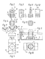
- a side view of a rod lock 10 can be seen, mounted on the inside of a door panel 12, which door panel 12 is hinged to a cabinet housing 14 and can be locked in the closed position by means of the rod lock 10.
- the rod lock 10 comprises a rod drive 16 with a handle and locking tongue 18, which cannot be seen here and can be operated from the outside Locking of the door leaf in the central area, as well as two rods 20 axially displaceable by the rod drive 16, which effect the locking of the door leaf at the upper and lower ends and which are slidably mounted near these locking points in rod guides 22, which in turn are carried by retaining tabs 24, which are preferably on the inner surface of the door leaf 12 is dotted or glued.
- the rods 20 were so-called flat ribbon rods, which also see FIG. 17, have an opening 26 at their end pointing towards the center of the door leaf, with which they can be plugged onto a fastening bolt 28, which in turn is attached by one is held in the rod drive 16 axially displaceably mounted drive projection 30.
- a second guide 122 which is arranged near the rod drive 16, can also be seen, which can be expedient if the drive lugs 30 protrude relatively far from the rod drive box.
- Such locking rods 20 usually have an impeller 32 (see also FIG. 9) at their end facing the lower or upper edge of the door leaf, with which the rod end runs up and is supported on a bent part 34 of the control cabinet housing 14.
- this impeller shown for example in FIG. 15 with respect to the impeller 132 there, enables it to be pushed through the rod guide 22, and if no lateral insertion into the rod guide is guaranteed, the rod 20 can only be in this way
- Rod guide 22 are mounted so that it is inserted axially with its end opposite the impeller 32 in the rod guide 22.
- the rod guide 22 with the rod 20 already inserted can be mounted on the holding bracket 24 and, for example, by subsequently rotating the rod guide 22 with respect to the holding bracket 24 (or alternatively also the door leaf 12 itself), the rod 20 being simultaneously rotated by a pivoting angle 38 ( of, for example, 45 °) and, on this occasion, advantageously with its bore 26 pushed over the fastening bolt 28 of the drive projection 30 and then can be fixed by means of a nut which can be screwed onto the fastening bolt or a cotter pin or the like which can be guided by it.
- a pivoting angle 38 of, for example, 45 °
- the rod guide 22 comprises, as shown, a foot part 40 and a guide part 44 carried by the foot part 40, which slidably receives the rod and holds a distance from the holding surface 42 (see FIG. 9), the foot part 40 having an outer cross section 46 which deviates from the circular shape. 4, has, in the present case, a square shape with flattened or truncated, somewhat rounded edges or flats 48.
- the holding surface 42 on which the rod guide 22 is to be mounted can be formed by the door leaf 12 itself, or from a mounting bracket or mounting strip 50 placed on the door leaf, this holding surface 42 having an opening 52 adapted to the outer cross section 46 for receiving the rod guide 22, but this non-circular peripheral contour of the opening 52 with respect to the corresponding outer contour of the rod guide 22 in the operating position is twisted, namely g 7 by 45 °.
- a circumferential groove 54 arranged in the circumference of the foot part 40 has a groove width 56 which corresponds to the thickness of the thin-walled holding surface 42, that is to say for example the door leaf thickness or the thickness of the holding bracket 50 can accommodate, and a contour of the groove bottom 58, which is circular.
- the groove bottom circle 58 touches the side edges 60 of the square-shaped outer cross section, so that a groove is formed only in the flattened corner areas 48.
- the rounded edges 48 can be rounded so that they are coaxial with the circle 58.
- the rod guide 22 is rotated, for example, from the position shown in FIGS. 7 and 8 by approximately 45 °, the holding areas 62 reach the correspondingly shaped opening areas 66 and are thereby released.
- the rod guide 22 can now be pulled out of the opening 52.
- the rod guide 22 can also be pushed into the opening 52 in this position, a rod 20 inserted into the rod guide 22 then taking the position shown in FIG. 1 below, the insertion being carried out until groove 54 with the holding surface 42 forming wall (for example the door leaf 12 or bracket 50) is aligned, whereupon (for example by pivoting the rod 20 in the direction of the angle 38) the retaining areas 62 of the groove from the breakthrough area 66 into the edge area 64 and thereby the Set rod guide 22.
- the holding surface 42 forming wall for example the door leaf 12 or bracket 50
- a plurality of grooves running parallel to one another can also be arranged axially one behind the other, see reference numerals 54, 54 'and 54''.
- Such a change in distance would be conceivable, for example, if sealing strips 68, which can have different thicknesses, are arranged between door leaf 12 and door frame, see for example FIG. 17.
- the foot part 40 of the rod guide shown in FIG. 2 merges in one piece into the guide part 44, which has a guide opening 70, similar to the prior art (EP 0 035 175 A1) shown in FIG. 4b there.
- the guide opening 70 which can be seen here is suitable both for flat bars (lower rectangular cross-sectional area of the opening) and for round bars (upper half of the circle in connection with part of the lower half of the rectangle) and, as can be seen in FIG. 3, has a somewhat widening outwards Cross-sectional extent to allow a certain pivoting of the rod in the guide, which facilitates assembly and enables a pivoting movement of the rods occurring simultaneously with the displacement in some rod drives.
- the foot part 40 is provided with a recess 72, so that the wall thicknesses occurring here are not all too different overall, so that distortions due to material expansion due to temperature changes (relatively large in the case of plastic) do not affect the mode of operation disturbing distortions.
- the rod guide 22 is in the holding position, as shown in Fig. 8 z. B. is shown, held by the rod 20 so that no unwanted twisting and thus sliding out of the opening 52 can occur. Still can an additional safeguard against undesired rotation can be provided, for example to prevent the rod guide 22 from sliding out when a rod 20 has not yet been installed.
- two knobs or projections 74 starting from the groove bottom 58 can be seen, which have such an extension that they lie against the breakthrough edge 76 which recesses in this area with respect to the circular groove bottom and thus an unwanted one Prevent twisting.
- knobs or projections 74 are nonetheless flexible enough to enable a deliberate twisting, in which process the material (also as a result of the cavity 72) withdraws and an overcoming of the obstacle formed by the edge 76 is made possible.
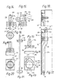
- the retaining bracket 50 which can be seen in FIG. 9 is shown in a top view in FIG. 5 and in a side view in FIG. 6 (or view from below with respect to FIG. 5), and is drawn out again in FIG. 10, but here the rod guide 22 is inserted, in the position in which the rod guide 22 is held by the bracket 50.
- a rod guide 122 can be seen, the foot part of which is constructed similarly to the foot part in the embodiment according to FIGS. 2 to 4, whose However, the guide part has an opening 170, which is provided for a flat bar in an arrangement perpendicular to the holding surface 42 (in FIG. 3 it was a parallel arrangement).
- the opening 170 is again flared in the form of a funnel in order to allow a certain pivoting in the direction of the flat strip bar plane.
- Such flat ribbon rods in Fig. 21 is one Ribbon bar 120 shown in a side view, often carry locking pins 78 along their extension, which are firmly riveted, for example, by a rivet 80, and therefore cannot be removed for assembly purposes.
- EP 0 261 265 A1 describes the problems that arise.
- an embodiment is provided which can be seen in a side view in FIG. 14, in which the foot part 140 is cut open axially (reference number 86), which cutting line 86 divides the foot part end into two foot part halves 82, 84 which, however, are held together in an articulated manner by the guide part 144.
- the two halves 82, 84 can be bent apart as a result of this articulation and then allow the insertion of a flat ribbon rod 120 now not in the axial direction but in the lateral direction, so that, for example, locking pins 78 do not interfere.
- the two halves 82, 84 can be folded together again and then inserted into a suitably shaped opening 52 of a retaining tab 50 or the like and then rotated through 45 °.
- the guide part 144 is thereby held on the one hand in the axial direction, and on the other hand the two halves 82, 84 are prevented from radially diverging.
- a funnel-shaped extension 88 can be provided at the outer end of the cutting line 86.
- the rod guide 122 shown in FIG. 14 is provided with two grooves 54 and thus also allows a change in distance.
- the similarly designed embodiment shown in FIG. 22, on the other hand, has only one groove 54.
- the advantage of this more compact embodiment is that it is in the very flat reinforcement rib 90, which is provided for other reasons, can be mounted, which is often provided in switch cabinets at edge areas and is shown in FIG. 17.
- This reinforcing rib 90 is part of a bend angle 92, which is used for fastening switch cabinet components and is usually found in switch cabinets. If you give this already existing bevel angle in the area of the rod guide to be attached a deflection or bulge, as designated by the reference number 90, a rod guide 122 according to FIG. 14 with its lower groove 54 'or a rod guide 222 with its single groove 54 in a bevel angle 92 having a corresponding opening 52, without special holding means having to be attached to the switch cabinet having to be provided.
- such a flat ribbon rod 220 is often provided with a crank 94 so as to be able to guide the rod closer to the door leaf 12, apart from the end of the rod 220 which carries the idler wheel 132, where the recessed bending part 134 of the cabinet body 14 has to be received .
- the rod 220 cannot easily be pivoted parallel to the door leaf surface, as can be seen in FIG. 1, in order to fix the rod guide 122 by turning through 45 °. You must also be able to pivot the rod 220 away from the door leaf surface, as shown in dashed lines in Fig. 15. In this position, the cranked part of the rod 220 can then be pivoted freely in the desired manner by the fold 92.
- the guide opening 170 is divided in the direction of the foot part 140 in a first area 96 that extends approximately to the center of the bar guide and runs approximately parallel to the door leaf surface, or in a second area 98 that runs obliquely in the direction of the door leaf. and the opposite in the guide opening Areas are initially divided accordingly into a region 100 running parallel to the slant and into a further region 101 running parallel to the door leaf, the distance between the mutually parallel guide surfaces 98 and 100 or 96 and 101, measured perpendicular to their direction of travel, being the same the (or only slightly larger) rod cross-sectional extent 103. The rod can thus be pushed in in a direction pivoted slightly away from the door leaf and then pivoted in the direction parallel to the door leaf surface, which position can be seen in FIG. 17.
- the bracket 50 can also be placed specifically on a door leaf or the like and, for example, spot welded, for which purpose its bracket legs can carry spot welding approaches 105.
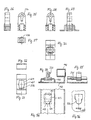
- the opening does not necessarily have to have the shape described in the previous embodiments, but can also see FIGS. 23, 24 consist of two openings of the same size, but rotated by 45 ° to one another and also shifted by a dimension 107, again one Square shape would be conceivable, again with rounded corners. If this displacement 107 is approximately half a rectangular edge length, there are two fastening options for a rod guide of the previously described circumferential contour with respect to the foot part: on the one hand, as before, the fastening can be carried out by turning through 45 °, either the upper half (axial line 109) or the half of the edge length shifted lower area (axial line 111) could be used, it only being necessary to ensure that the rod guide 22 thus assembled cannot move along the line 113.
- the upper breakthrough part corresponds to the breakthrough 52 according to FIG. 5 and is therefore suitable for rod guides which can be mounted in this breakthrough 52.
- the axis must of the guide opening 270 can be rotated by 45 ° with respect to the contour of the foot part 240, as is also the case in the embodiment according to FIG. 22.
- a rod guide designed in this way can then also be defined in another way: it could be inserted into the upper opening area (line 109) and then (instead of being rotated) simply moved down into the lower opening area (line 111) by the distance 107, whereupon the groove areas 54 encompass the edge areas of the opening 126 formed by the holding bracket 150 in the manner already described and thereby hold the rod guide 222 in place.
- two tongues 115 are provided, which rest against the breakthrough edges 117 or the soffit and thereby prevent sliding back. Similar tongues are also provided in the embodiment shown in FIGS. 14 to 16, which, however, are only effective in connection with the lowermost groove 54 ', since tongues provided for higher-lying grooves make it more difficult to insert them in these further-lying grooves would.
- Fastening by displacement is also provided in the embodiment according to FIGS. 33 to 36, the opening forming a semicircle 190, with a first rectangle 121 smoothly adjoining the semicircular chord with the circular diameter as the longitudinal extension and the circular half diameter as the transverse extension, and with a on the free long side of the first rectangle, in turn adjoining second rectangle 123 with a transverse extent corresponding to the circular diameter and a longitudinal extent that exceeds the circular diameter.
- a rod guide 322 can be inserted into such an opening, the outer contour of which has the contour of the rectangle 123, see for example the basic structure of the embodiment according to FIGS. 25 to 27 or 28 to 30.
- the rod guide 322 can be shifted in the region 119, 121, that is to say by the circle diameter, and will held there. In this position, the rod guide 322 can be held in place by a projection or tongue 215 which lies against the edge 125, or, e.g. B. in reverse orientation, in an additional opening 127 provided.
- the rod guide 322 can also be fastened with the same foot shape by turning, for example if an opening is provided according to the shape of FIG. 31, see reference number 226.
- the outer contour of the foot then also has this shape, namely the shape of a rectangle with a the two long sides 129 of the rectangle intersecting circle 131 arranged coaxially to the center of the rectangle.
- the diameter of the circle 131 corresponds to the contour of the groove bottom, 158 in FIG. 27, so that a free rotation within the circle 131 is possible.
- the foot of the embodiment shown in FIGS. 25 to 27 can be inserted into the opening 129 in a certain orientation in order to then rotate it through 90 ° and thereby fix it. This position can be seen in FIGS. 28 to 30.
- the embodiment according to FIGS. 26 to 30 has a guide part with a key-like guide opening 270, the round area of the key-like opening being suitable for round bars, the beard part, including the round area) for flat bars.
Applications Claiming Priority (2)
| Application Number | Priority Date | Filing Date | Title |
|---|---|---|---|
| DE9004757U | 1990-04-27 | ||
| DE9004757U DE9004757U1 (fr) | 1990-04-27 | 1990-04-27 |
Publications (3)
| Publication Number | Publication Date |
|---|---|
| EP0454077A2 true EP0454077A2 (fr) | 1991-10-30 |
| EP0454077A3 EP0454077A3 (en) | 1992-01-08 |
| EP0454077B1 EP0454077B1 (fr) | 1994-11-30 |
Family
ID=6853255
Family Applications (1)
| Application Number | Title | Priority Date | Filing Date |
|---|---|---|---|
| EP91106573A Expired - Lifetime EP0454077B1 (fr) | 1990-04-27 | 1991-04-24 | Moyens de guidages pour les barres d'une espagnolette |
Country Status (2)
| Country | Link |
|---|---|
| EP (1) | EP0454077B1 (fr) |
| DE (2) | DE9004757U1 (fr) |
Cited By (2)
| Publication number | Priority date | Publication date | Assignee | Title |
|---|---|---|---|---|
| WO2008125318A2 (fr) * | 2007-04-14 | 2008-10-23 | Dirak Dieter Ramsauer Konstruktionselemente Gmbh & Co. Kg | Système de guidage de tiges réglable |
| EP2767659A3 (fr) * | 2013-02-14 | 2015-07-22 | EMKA BESCHLAGTEILE GmbH & Co. KG | Guide à barres rondes réglable en hauteur |
Families Citing this family (2)
| Publication number | Priority date | Publication date | Assignee | Title |
|---|---|---|---|---|
| DE202005015135U1 (de) * | 2005-09-24 | 2007-02-15 | Ramsauer, Dieter | Auf einen Stehbolzen montierbare Führung für eine Rundstange |
| DE102006033752B4 (de) * | 2006-07-21 | 2014-07-10 | Abb Ag | Schaltschrank |
Citations (5)
| Publication number | Priority date | Publication date | Assignee | Title |
|---|---|---|---|---|
| FR2273967A1 (fr) * | 1974-06-04 | 1976-01-02 | Itw De France | Piece de fixation imperdable et positionnee |
| DE7621270U1 (de) * | 1976-07-06 | 1976-12-23 | Fa. Emil Krachten Jun., 5620 Velbert | Stangenverschluss |
| FR2375414A1 (fr) * | 1976-12-23 | 1978-07-21 | Siegenia Frank Kg | Dispositif pour la fixation des lattes de recouvrement des ferrures a tiges actives destinees a des portes et fenetres en bois ou matiere synthetique |
| GB2020731A (en) * | 1978-05-09 | 1979-11-21 | Springfix Befestigungstechnik | Fastening elements |
| EP0035175A1 (fr) * | 1980-02-28 | 1981-09-09 | Friedhelm Runge | Moyens de guidage pour barres de fermeture pour armoires pour appareillage de commutation électrique ou similaires |
-
1990
- 1990-04-27 DE DE9004757U patent/DE9004757U1/de not_active Expired - Lifetime
-
1991
- 1991-04-24 EP EP91106573A patent/EP0454077B1/fr not_active Expired - Lifetime
- 1991-04-24 DE DE59103618T patent/DE59103618D1/de not_active Expired - Fee Related
Patent Citations (5)
| Publication number | Priority date | Publication date | Assignee | Title |
|---|---|---|---|---|
| FR2273967A1 (fr) * | 1974-06-04 | 1976-01-02 | Itw De France | Piece de fixation imperdable et positionnee |
| DE7621270U1 (de) * | 1976-07-06 | 1976-12-23 | Fa. Emil Krachten Jun., 5620 Velbert | Stangenverschluss |
| FR2375414A1 (fr) * | 1976-12-23 | 1978-07-21 | Siegenia Frank Kg | Dispositif pour la fixation des lattes de recouvrement des ferrures a tiges actives destinees a des portes et fenetres en bois ou matiere synthetique |
| GB2020731A (en) * | 1978-05-09 | 1979-11-21 | Springfix Befestigungstechnik | Fastening elements |
| EP0035175A1 (fr) * | 1980-02-28 | 1981-09-09 | Friedhelm Runge | Moyens de guidage pour barres de fermeture pour armoires pour appareillage de commutation électrique ou similaires |
Cited By (6)
| Publication number | Priority date | Publication date | Assignee | Title |
|---|---|---|---|---|
| WO2008125318A2 (fr) * | 2007-04-14 | 2008-10-23 | Dirak Dieter Ramsauer Konstruktionselemente Gmbh & Co. Kg | Système de guidage de tiges réglable |
| WO2008125167A2 (fr) * | 2007-04-14 | 2008-10-23 | Dieter Ramsauer | Système de guidage de tiges réglable |
| WO2008125167A3 (fr) * | 2007-04-14 | 2009-01-22 | Dieter Ramsauer | Système de guidage de tiges réglable |
| WO2008125318A3 (fr) * | 2007-04-14 | 2009-01-22 | Dirak Dieter Ramsauer Konstruk | Système de guidage de tiges réglable |
| US8251413B2 (en) | 2007-04-14 | 2012-08-28 | Dirak Dieter Ramsauer Konstruktionselemente Gmbh | Adjustable bar guide |
| EP2767659A3 (fr) * | 2013-02-14 | 2015-07-22 | EMKA BESCHLAGTEILE GmbH & Co. KG | Guide à barres rondes réglable en hauteur |
Also Published As
| Publication number | Publication date |
|---|---|
| EP0454077A3 (en) | 1992-01-08 |
| DE59103618D1 (de) | 1995-01-12 |
| DE9004757U1 (fr) | 1991-08-22 |
| EP0454077B1 (fr) | 1994-11-30 |
Similar Documents
| Publication | Publication Date | Title |
|---|---|---|
| EP1131521B1 (fr) | Fermeture a verrou rotatif avec unite de traction | |
| EP1709270B1 (fr) | Fixation de pinces pour le montage de dispositifs de ferrures, tels que fermetures, elements de charniere, poignees dans des passages au travers d'une paroi mince | |
| EP0261266B1 (fr) | Fermeture par tringles à poignée basculante | |
| DE3007488C2 (de) | Stangenführung eines Treibstangenverschlusses an Schaltschranktüren od.dgl. | |
| EP1747334A1 (fr) | Poignee creuse | |
| WO1996010679A1 (fr) | Fermeture a barre | |
| EP1613828B1 (fr) | Dispositif de fermeture d'une porte | |
| EP0454077B1 (fr) | Moyens de guidages pour les barres d'une espagnolette | |
| DE102013211864B4 (de) | Anordnung zur Befestigung eines Pfostens an einer Kunststoff-Rahmenleiste eines Fensters oder einer Türe mittels eines Pfostenverbinders aus Kunststoff | |
| DE4013441C2 (de) | Stangenführung für die Stangen eines Stangenverschlusses | |
| DE4220033A1 (de) | Stangenverriegelung fuer aus flachmaterial bestehende stangen aufweisende blechschranktuerverschluesse | |
| DE19828233A1 (de) | Wandkonsole | |
| DE4006706C2 (de) | Vorreiberverschluß für Klappen, Seitenverkleidung, oder dgl. aus dünnem Wandmaterial | |
| DE19737538A1 (de) | Betätigungsgetriebe für einen Treibstangenbeschlag | |
| DE19742512C2 (de) | Schubstangenverschluß für eine an einem Schaltschrank-Korpus angelenkte Schranktüre | |
| DE10001662A1 (de) | Schutzbeschlag | |
| EP1126110B1 (fr) | Dispositif de fermeture pour portes et fenêtres | |
| DE3603591C1 (en) | Pivoting-drive and locking mechanism for closure flaps of ventilation appliances | |
| DE3506870A1 (de) | Tuerverschluss mit hebelfoermiger versenkbarer handhabe, insbesondere an schaltschranktueren | |
| DE202008005541U1 (de) | Beschlagteil mit Schnellmontageeinrichtung | |
| DE19717188C1 (de) | Dreh- oder Schubstangenschloß | |
| CH654732A5 (de) | Schrank mit mindestens einer schwenkbaren tuere. | |
| DE202004004066U1 (de) | Verschluß mit Klemmbefestigung | |
| DE2614810B2 (de) | Halte- und Führungsvorrichtung für Möbelschiebetüren | |
| AT408784B (de) | Anordnung zum befestigen von im wesentlichen u-förmigen führungsschienen für rolladen sowie baugruppe aus führungsschiene und halteteilen für eine solche anordnung |
Legal Events
| Date | Code | Title | Description |
|---|---|---|---|
| PUAI | Public reference made under article 153(3) epc to a published international application that has entered the european phase |
Free format text: ORIGINAL CODE: 0009012 |
|
| AK | Designated contracting states |
Kind code of ref document: A2 Designated state(s): DE FR GB |
|
| PUAL | Search report despatched |
Free format text: ORIGINAL CODE: 0009013 |
|
| AK | Designated contracting states |
Kind code of ref document: A3 Designated state(s): DE FR GB |
|
| 17P | Request for examination filed |
Effective date: 19920702 |
|
| 17Q | First examination report despatched |
Effective date: 19930722 |
|
| GRAA | (expected) grant |
Free format text: ORIGINAL CODE: 0009210 |
|
| AK | Designated contracting states |
Kind code of ref document: B1 Designated state(s): DE FR GB |
|
| PG25 | Lapsed in a contracting state [announced via postgrant information from national office to epo] |
Ref country code: GB Effective date: 19941130 Ref country code: FR Effective date: 19941130 |
|
| REF | Corresponds to: |
Ref document number: 59103618 Country of ref document: DE Date of ref document: 19950112 |
|
| EN | Fr: translation not filed | ||
| GBV | Gb: ep patent (uk) treated as always having been void in accordance with gb section 77(7)/1977 [no translation filed] |
Effective date: 19941130 |
|
| PLBE | No opposition filed within time limit |
Free format text: ORIGINAL CODE: 0009261 |
|
| STAA | Information on the status of an ep patent application or granted ep patent |
Free format text: STATUS: NO OPPOSITION FILED WITHIN TIME LIMIT |
|
| 26N | No opposition filed | ||
| PGFP | Annual fee paid to national office [announced via postgrant information from national office to epo] |
Ref country code: DE Payment date: 20040604 Year of fee payment: 14 |
|
| PG25 | Lapsed in a contracting state [announced via postgrant information from national office to epo] |
Ref country code: DE Free format text: LAPSE BECAUSE OF NON-PAYMENT OF DUE FEES Effective date: 20051101 |