EP0454062B1 - Rohrleitungsanlage mit Feuerlöschsprinklern und Verfahren zum Rohreinbau für die Montage von Feuerlöschsprinklern - Google Patents
Rohrleitungsanlage mit Feuerlöschsprinklern und Verfahren zum Rohreinbau für die Montage von Feuerlöschsprinklern Download PDFInfo
- Publication number
- EP0454062B1 EP0454062B1 EP91106523A EP91106523A EP0454062B1 EP 0454062 B1 EP0454062 B1 EP 0454062B1 EP 91106523 A EP91106523 A EP 91106523A EP 91106523 A EP91106523 A EP 91106523A EP 0454062 B1 EP0454062 B1 EP 0454062B1
- Authority
- EP
- European Patent Office
- Prior art keywords
- joint
- pipe
- pipes
- piping arrangement
- flexible joint
- Prior art date
- Legal status (The legal status is an assumption and is not a legal conclusion. Google has not performed a legal analysis and makes no representation as to the accuracy of the status listed.)
- Expired - Lifetime
Links
- 238000000034 method Methods 0.000 title claims description 8
- XLYOFNOQVPJJNP-UHFFFAOYSA-N water Substances O XLYOFNOQVPJJNP-UHFFFAOYSA-N 0.000 claims description 11
- 239000000463 material Substances 0.000 claims description 2
- 210000002445 nipple Anatomy 0.000 description 4
- 238000005260 corrosion Methods 0.000 description 1
- 230000007797 corrosion Effects 0.000 description 1
- 238000007689 inspection Methods 0.000 description 1
- 238000009434 installation Methods 0.000 description 1
- 239000007788 liquid Substances 0.000 description 1
- 238000012423 maintenance Methods 0.000 description 1
- 229910052751 metal Inorganic materials 0.000 description 1
- 239000002184 metal Substances 0.000 description 1
- 150000002739 metals Chemical class 0.000 description 1
- 230000008439 repair process Effects 0.000 description 1
Images


Classifications
-
- A—HUMAN NECESSITIES
- A62—LIFE-SAVING; FIRE-FIGHTING
- A62C—FIRE-FIGHTING
- A62C35/00—Permanently-installed equipment
- A62C35/58—Pipe-line systems
-
- A—HUMAN NECESSITIES
- A62—LIFE-SAVING; FIRE-FIGHTING
- A62C—FIRE-FIGHTING
- A62C35/00—Permanently-installed equipment
- A62C35/58—Pipe-line systems
- A62C35/68—Details, e.g. of pipes or valve systems
Definitions
- This invention relates to a piping arrangement according to the preamble of claim 1, as known from BE-A-470.380, and a method of installing pipes for such a piping arrangement.
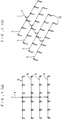
- sprinkler heads of this type are arranged in plurality in spaced apart relation so as to enable fire water release to spread generally over the entire room space. Hitherto, it has been known to install pipes for sprinkler head mounting in manner as known from BE-A-470.380 and as shown in FIGS. 7 and 8, for example.
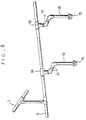
- the conventional piping arrangement shown comprises a plurality of auxiliary water-supply pipes 5 led from and arranged in intersecting relation to a main supply pipe 1, and mounting members such as tees 16, elbows 17, 17, and nipples 18 for mounting a plurality of sprinkler heads 15 at specified intervals to each auxiliary water-supply pipe, the mounting members being arranged in a suitable combination between each auxiliary pipe and each individual sprinkler head 15 as shown in FIG. 8.
- each auxiliary pipe 5 In the conventional pipe installing method, it is necessary that each auxiliary pipe 5 must be provided with such number of branch pipes that corresponds to the number of sprinkler heads 15 to be mounted in position, and moreover, as stated above, a large number of parts are required in pipework for connection between each auxiliary pipes 5 and individual sprinkler heads 15. As such, the required piping arrangement is very complicated, and such complicated pipework is required with respect to individual sprinkler heads. This poses a fatal problem that the pipe installing work at the site is very complex and troublesome.
- This invention has been developed with a view to solving the foregoing problem with the prior art, and accordingly it is a primary object of the invention to provide a simplified piping arrangement for sprinkler head mounting thereby to minimize the number of parts required for pipe installation and enable a series of pipework at the site to be carried out at ease and quickly.
- the invention also provides a method of installing pipes according to claim 7.
- the resulting piping arrangement which carries a plurality of sprinkler heads, provides good practical convenience and involves a reduced number of parts as compared with the prior art piping arrangement, thus contributing much toward simplified pipe installing operation.
- nipples 3 are first connected individually to tees 2 which are connected at specified intervals to a fire-water main supply pipe 1 installed in the ceiling of a house, and to each of the nipples 3 is in turn connected an auxiliary water-supply pipe 5 through a tee 4.
- a plurality of auxiliary water-supply pipes 5 are arranged in parallal to one another and in intersecting relation to the main supply pipe 1 as shown in FIG. 1.
- tees 6 are incorporated into each auxiliary supply pipe 5 at specified intervals, and to each tee 6 is connected an inlet port 8 of a so-called five-port connection joint 10 through a nipple 7.
- a joint 10 as FIG. 3 shows, comprises the inlet port 8, which is formed generally centrally of the joint, and four outlet ports 9 ... formed in a cross pattern, each outlet port 9 being formed on its outer periphery 19 with an externally threaded portion 20.
- Joint pipes 11, 13 are previously connected respectively to opposite ends of a flexible joint pipe 12 having good flexibility, and a sprinkler head 15 is connected to the one joint pipe 13 through an elbow 14. Then, the joint pipe 11 may be simply connected to one outlet port 9 of the five-port connection joint 10. This affords reduction of required work time at the site.
- clamping elements 22 for the flexible joint pipe 12 are brought in thread engagement with respective extarnally threaded portions 20 of the joint pipes 11, 13 so that annular collars 21 of the flexible joint pipe 12 are respectively pressed on the back by the clamping elements 22, whereby each of the annular collars 21 and the front end of one of the joint pipes 11, 13 are pressed against each other through an O-ring 23.
- the flexible joint pipe 12 can be easily connected to the joint pipes 11, 13.
- each flexible joint pipe 12 can be connected to joint pipes 11 or 13 having an inner diameter l1 almost equal to the inner diameter l2 of the flexible joint pipe 12, and this provides an advantage that a desired amount of fire water can be allowed to flow in good condition through the entire piping arrangement without any drop in flow rate being caused by a friction loss due to liquid friction at any such pipe connection.
- Sprinkler heads 15 are fixedly mounted in position on the ceiling or the like through the intermediary of elbows 14 , etc.
- the fact that the flexible joint pipes 12 are quite flexible and light is particularly advantageous in that they are very easy to handle; they can simply be trained over the ceiling without use of any hanger means.
- a cylindrical movable member 19 of an insulative material, such as rubber, may be movably fitted on the flexible joint pipe 12 as shown in FIG. 5, so that possible electrolytic corrosion due to contact of different knids of metals can be prevented by moving the movable member 19 to such portion of contact.
- the piping arrangement can be maintained in good condition over a long period of time.
- each auxiliary pipe 5 branches, at each specified point, in four directions through the intermediary of one five-port connection joint 10, and accordingly four sprinkler heads 15 can be mounted for each group of such four branches.
- the necessity of providing discrete complex piping means is also eliminated.
- the required piping arrangement for sprinkler head mounting is simplified as a whole, which enables reduction in the number of parts required and affords easy and prompt execution of installing works involved.
- the invention provides a further advantage that piping repairs and other maintenance and inspection operations can be carried out at ease.
- connection joints 10 are employed to branch water supply in four directions, but it is to be understood that the configuration of such joint according to the invention is not limited to the one shown and may be suitably changed or varied according to the location, object, etc. for which such joint is to be used. It is only required that such joint should have at least two outlet ports.
- flexible joint pipes 12 are connected to outlet ports of each joint 10 or elbows 14 through joint pipes 11, 13; but it is understood that the piping arrangement for water supply from auxiliary supply pipes 5 to sprinkler heads 15 is not particularly limited.
- flexible joint pipes 12 may be connected directly to outlet ports of each joint 10 or elbows 10, and not through joint pipes 11, 13, as shown in FIG. 6. It is only required that sprinkler heads 15 are connected to auxiliary supply pipes 5 through flexible joint pipes 12.
Landscapes
- Health & Medical Sciences (AREA)
- Public Health (AREA)
- Business, Economics & Management (AREA)
- Emergency Management (AREA)
- Fire-Extinguishing By Fire Departments, And Fire-Extinguishing Equipment And Control Thereof (AREA)
Claims (7)
- Leitungsanordnung für die Versorgung von Sprinklerköpfen mit Wasser, mit:
einer in der Decke eines Hauses angeordneten Hauptversorgungsleitung (1); jeweils mit der Hauptversorgungsleitung (1) in einem beabstandeten Verhältnis verbundenen Nebenwasserversorgungsleitungen (5); und Sprinklerköpfen (15), die mit jeder der Nebenwasserversorgungsleitungen (5) in beabstandetem Verhältnis zueinander verbunden sind, gekennzeichnet durch Sprinklerkopfanordnungen, wobei jede der Sprinklerkopfanordnungen wenigstens zwei Sprinklerköpfe (15) aufweist, die entsprechend durch flexible Verbindungsleitungen (12) mit Auslaßöffnungen (9) einer gemeinsamen Knotenverbindung (10) verbunden sind, wobei die Knotenverbindung (10) eine mit der Nebenversorgungsleitung (5) verbundene Einlaßöffnung (8) besitzt. - Leitungsanordnung nach Anspruch 1, wobei die Sprinklerköpfe (15) mit jeweiligen Auslaßöffnungen (9) jeder Verbindung (10) durch eine Verbindungsleitung (11, 13) und einer der flexiblen Verbindungsleitungen (12) verbunden sind.
- Leitungsanordnung nach Anspruch 1, wobei jede der Verbindungen (10) vier Auslaßöffnungen (9) besitzt.
- Leitungsanordnung nach Anspruch 1, weiterhin mit ringförmigen Bünden (21), die am Außenumfang jeder flexiblen Verbindungsleitung (12) an gegenüberliegenden Enden ausgebildet sind, einem mit einem Außengewinde versehenen Abschnitt (20), der an dem Außenumfang jeder Auslaßöffnung (9) jeder Verbindung (10), mit der die flexible Verbindungsleitung (12) verbunden ist, ausgebildet ist, und einem Klemmelement (22), welches mit dem Außengewindeabschnitt (20) in Gewindeeingriff bringbar ist, wodurch, wenn der ringförmige Bund (21) an der Rückseite durch das Klemmelement (22) mit Druck beaufschlagt ist, die Vorderseite des ringförmigen Bundes (21) durch ein Dichtungsglied (23) gegen das vordere Ende der Verbindung (10) in Anlage gebracht ist.
- Leitungsanordnung nach Anspruch 1, weiterhin mit ringförmigen Bünden (21), die am Außenumfang jeder flexiblen Verbindungsleitung (12) an gegenüberliegenden Enden ausgebildet sind, einem mit einem Außengewinde versehenen Abschnitt (20), der an dem Außenumfang jeder Verbindungsleitung (10), mit der die flexible Verbindungsleitung (12) verbunden ist, ausgebildet ist, und einem Klemmelement (22), welches mit dem Außengewindeabschnitt (20) in Gewindeeingriff bringbar ist, wodurch, wenn der ringförmige Bund (21) an der Rückseite durch das Klemmelement (22) mit Druck beaufschlagt ist, die Vorderseite des ringförmigen Bundes (21) durch ein Dichtungsglied (23) gegen das vordere Ende der Verbindung (10) in Anlage gebracht ist.
- Leitungsanordnung nach Anspruch 1, wobei wenigstens ein aus einem Isolierwerkstoff gefertigtes bewegbares Glied (19) an jeder flexiblen Verbindungsleitung (12) bewegbar angeordnet ist.
- Verfahren zum Einbau von Leitungen für eine Leitungsanordnung nach Anspruch 1, mit den folgenden Schritten:
Vorsehen einer Hauptversorgungsleitung an dem Dach eines Hauses;
Verbinden von jeweiligen Nebenwasserversorgungsieitungen mit der Hauptversorgungsleitung in beabstandeten Verhältnissen; und
Anordnen von wenigstens zwei Sprinklerköpfen beabstandet zueinander durch eine gemeinsame Knotenverbindung an jeder der Nebenwasserversorgungsleitungen.
Applications Claiming Priority (2)
| Application Number | Priority Date | Filing Date | Title |
|---|---|---|---|
| JP2106950A JPH07114819B2 (ja) | 1990-04-23 | 1990-04-23 | スプリンクラーヘッド取付用配管の施工方法とスプリンクラーヘッド取付用配管構造 |
| JP106950/90 | 1990-04-23 |
Publications (2)
| Publication Number | Publication Date |
|---|---|
| EP0454062A1 EP0454062A1 (de) | 1991-10-30 |
| EP0454062B1 true EP0454062B1 (de) | 1996-01-10 |
Family
ID=14446647
Family Applications (1)
| Application Number | Title | Priority Date | Filing Date |
|---|---|---|---|
| EP91106523A Expired - Lifetime EP0454062B1 (de) | 1990-04-23 | 1991-04-23 | Rohrleitungsanlage mit Feuerlöschsprinklern und Verfahren zum Rohreinbau für die Montage von Feuerlöschsprinklern |
Country Status (6)
| Country | Link |
|---|---|
| US (1) | US5327976A (de) |
| EP (1) | EP0454062B1 (de) |
| JP (1) | JPH07114819B2 (de) |
| KR (1) | KR940009689B1 (de) |
| CA (1) | CA2040829C (de) |
| DE (1) | DE69116206T2 (de) |
Families Citing this family (39)
| Publication number | Priority date | Publication date | Assignee | Title |
|---|---|---|---|---|
| JPH0584350U (ja) * | 1992-04-16 | 1993-11-16 | 大成建設株式会社 | スプリンクラーの配管構造 |
| JPH06210016A (ja) * | 1993-01-19 | 1994-08-02 | Goto Setsubi Kogyo Kk | 液体散布用配管設備における配管継ぎ足し工法 |
| JPH06210015A (ja) * | 1993-01-19 | 1994-08-02 | Goto Setsubi Kogyo Kk | 流体散布用配管設備における配管施工方法 |
| US5396959A (en) * | 1993-09-20 | 1995-03-14 | Pnm, Inc. | Sprinkler system |
| US5570745A (en) * | 1995-05-31 | 1996-11-05 | Pnm, Inc. | Relocatable sprinkler assemblage |
| US5842526A (en) * | 1995-09-26 | 1998-12-01 | Archer; Robert C. | Sprinkler head mounting system |
| US6044911A (en) * | 1996-09-06 | 2000-04-04 | Haase, Iii; Franz | Parallel-fed nonstagnant integrated water distribution network for domestic water and fire sprinkler application |
| US6422319B2 (en) * | 1996-09-06 | 2002-07-23 | Haase, Iii Franz P. | Water distribution network for domestic water and fire protection application |
| US6241024B1 (en) * | 1996-09-06 | 2001-06-05 | Haase, Iii Franz P. | Parallel-fed nonstagnant integrated water distribution network for domestic water and fire sprinkler application |
| DE19723589A1 (de) * | 1997-06-05 | 1998-12-10 | Total Feuerschutz Gmbh | Vorrichtung zum Verbinden der Sammelrohre mit den Löschbereichsventilen einer Feuerlöschanlage mit in Gasflaschen gefülltes Hochdrucklöschgas |
| US6076608A (en) | 1998-05-11 | 2000-06-20 | Pnm, Inc. | Fire-suppression sprinkler system and method for installation and retrofit |
| US6488097B1 (en) | 1999-01-08 | 2002-12-03 | Pnm, Inc. | Fire protection sprinkler head support |
| US6058975A (en) * | 1999-08-26 | 2000-05-09 | Hui-Chen; Chao | Connection member of water control valve |
| EP1118355A1 (de) * | 2000-01-18 | 2001-07-25 | Alan P. Kretschmer | Vorrichtung und Verfahren zur Brandunterdrückung |
| US6158519A (en) * | 2000-01-18 | 2000-12-12 | Kretschmer; Alan P. | Fire suppression method and apparatus |
| AU776617B2 (en) * | 2000-02-10 | 2004-09-16 | Franz Haase Iii | Parallel-fed nonstagnant integrated water distribution network for domestic water and fire sprinkler |
| EP1132528B1 (de) * | 2000-03-08 | 2005-06-01 | Haase, Franz III | Parallel gespeistes integriertes Versorgungsnetz für nicht stagnierendes Wasser für Hauswasser und Sprinkleranlage |
| JP4649029B2 (ja) * | 2000-09-22 | 2011-03-09 | ヤマトプロテック株式会社 | スプリンクラーヘッド取付用配管の施工方法とスプリンクラーヘッド取付用配管構造 |
| DE10140942C1 (de) * | 2001-08-21 | 2003-08-14 | Preussag Ag Minimax | Zuführsystem für Löschmittel |
| US7896261B2 (en) * | 2003-03-14 | 2011-03-01 | Tony Holmes | Water distribution system |
| DE10348199A1 (de) * | 2003-10-16 | 2005-05-25 | Mrklas, Louis, Ing.(grad.) | Vorrichtung zum Löschen von Bränden auf Vegetationsflächen |
| ES2304842B1 (es) * | 2006-04-11 | 2010-04-06 | Ignacio Saenz Peñate | Sistema aplicable a la lucha contra incendios. |
| US7699117B2 (en) * | 2007-05-09 | 2010-04-20 | The Wanda Group | Fire protection sprinkler system and related apparatus |
| EP2475921B1 (de) | 2009-09-11 | 2014-11-19 | Victaulic Company | Flexible anordnung für sprinkler |
| US20120145418A1 (en) * | 2010-12-06 | 2012-06-14 | Kuojui Su | Misting blanket fire protection system |
| US9358411B2 (en) | 2011-05-27 | 2016-06-07 | Victaulic Company | Flexible dry sprinkler |
| US8887822B2 (en) * | 2012-06-01 | 2014-11-18 | Reliable Automatic Sprinkler Co., Inc. | Flexible dry sprinklers |
| JP6251050B2 (ja) * | 2014-01-17 | 2017-12-20 | 三菱航空機株式会社 | 航空機の消火設備および航空機 |
| WO2015184157A1 (en) | 2014-05-28 | 2015-12-03 | The Reliable Automatic Sprinkler Co. | Bracket for installation of fire sprinklers |
| MX384432B (es) | 2014-06-27 | 2025-03-14 | Asc Eng Solutions Llc | Abrazadera ajustable y cubo para soporte de manguera flexible. |
| CN104083836A (zh) * | 2014-07-09 | 2014-10-08 | 安徽康成工业产品设计有限公司 | 车间干粉管道灭火装置 |
| US10335620B2 (en) * | 2016-12-12 | 2019-07-02 | ScotBilt Homes, Inc. | Methods of making manufactured housing components and manufactured homes |
| US20180371780A1 (en) * | 2017-06-27 | 2018-12-27 | Doxa Central, L.L.C. | Methods and Apparatus for a Modular Parking System |
| US10981189B2 (en) * | 2017-07-07 | 2021-04-20 | Anvil International, Llc | Hanging connector for flexible sprinkler conduit |
| ES2736900A1 (es) * | 2018-06-29 | 2020-01-08 | Bayon Javier Seijas | Sistema liquidador de incendios |
| US12017103B2 (en) * | 2020-06-05 | 2024-06-25 | Tyco Fire Products Lp | Adapter for concealed sprinkler |
| CN113129543B (zh) * | 2020-12-07 | 2025-05-16 | 保定市世纪消防工程有限公司 | 一种基于人工智能的消防报警装置及报警方法 |
| US20240042256A1 (en) | 2021-03-08 | 2024-02-08 | Tyco Fire Products Lp | Systems and methods for sprinkler systems with flexible hose and rapid seal adapter |
| KR20250113650A (ko) * | 2024-01-19 | 2025-07-28 | 삼성에스디아이 주식회사 | 에너지 저장 장치 |
Family Cites Families (12)
| Publication number | Priority date | Publication date | Assignee | Title |
|---|---|---|---|---|
| BE470380A (de) * | ||||
| US1850937A (en) * | 1927-11-28 | 1932-03-22 | George S Messinger | Distributor |
| US2017841A (en) * | 1932-06-20 | 1935-10-22 | Gen Fire Extinguisher Co | Domestic sprinkler system |
| US2654346A (en) * | 1949-12-05 | 1953-10-06 | John W Goff | Poultry watering device |
| US3666015A (en) * | 1970-09-15 | 1972-05-30 | Factory Mutual Res Corp | Fluid flow control device |
| US3736955A (en) * | 1971-06-14 | 1973-06-05 | A Schlesser | Irrigation conduit stream divider |
| US3727694A (en) * | 1971-11-05 | 1973-04-17 | Unarco Industries | Sprinkler attachment for racks |
| FR2306716A1 (fr) * | 1975-04-07 | 1976-11-05 | Belles Ondes Forges | Raccord coulissant pour le montage de dispositif de securite contre l'incendie |
| JPS5521746U (de) * | 1978-07-29 | 1980-02-12 | ||
| JPS5540826U (de) * | 1978-09-08 | 1980-03-15 | ||
| JPS60142868A (ja) * | 1983-12-29 | 1985-07-29 | 松本 祐次郎 | スプリンクラ配管方法 |
| US4964470A (en) * | 1988-11-10 | 1990-10-23 | Mcdonald Plumbing & Heating Inc. | Sprinkler connection to scrubber duct |
-
1990
- 1990-04-23 JP JP2106950A patent/JPH07114819B2/ja not_active Expired - Lifetime
-
1991
- 1991-02-07 KR KR1019910002105A patent/KR940009689B1/ko not_active Expired - Fee Related
- 1991-04-19 CA CA002040829A patent/CA2040829C/en not_active Expired - Fee Related
- 1991-04-23 EP EP91106523A patent/EP0454062B1/de not_active Expired - Lifetime
- 1991-04-23 DE DE69116206T patent/DE69116206T2/de not_active Expired - Fee Related
-
1993
- 1993-10-21 US US08/140,818 patent/US5327976A/en not_active Expired - Fee Related
Also Published As
| Publication number | Publication date |
|---|---|
| JPH07114819B2 (ja) | 1995-12-13 |
| US5327976A (en) | 1994-07-12 |
| JPH045971A (ja) | 1992-01-09 |
| DE69116206D1 (de) | 1996-02-22 |
| EP0454062A1 (de) | 1991-10-30 |
| KR940009689B1 (ko) | 1994-10-15 |
| CA2040829A1 (en) | 1991-10-24 |
| DE69116206T2 (de) | 1996-05-23 |
| CA2040829C (en) | 1997-02-04 |
Similar Documents
| Publication | Publication Date | Title |
|---|---|---|
| EP0454062A1 (de) | Rohrleitungsanlage mit Feuerlöschsprinklern und Verfahren zum Rohreinbau für die Montage von Feuerlöschsprinklern | |
| US6422319B2 (en) | Water distribution network for domestic water and fire protection application | |
| US5944055A (en) | Control valve with swivel connector | |
| US6076545A (en) | Fire-control sprinkler system riser means | |
| US6321782B1 (en) | Apparatus for controlling the flow of fluids | |
| US4281683A (en) | Modular multiple-fluid component selection and delivery system | |
| US4215721A (en) | Modular multiple-fluid component selection and delivery system | |
| US6044911A (en) | Parallel-fed nonstagnant integrated water distribution network for domestic water and fire sprinkler application | |
| US7597361B2 (en) | Bulkhead fitting for an irrigation pipe | |
| US4047570A (en) | Sprinkler system for existing buildings | |
| US6241024B1 (en) | Parallel-fed nonstagnant integrated water distribution network for domestic water and fire sprinkler application | |
| JP2000515225A (ja) | 高純度、高腐食性ガス施設用ガス流制御装置 | |
| US6109535A (en) | Corrosion resistant irrigation machine | |
| US20030015326A1 (en) | Water distribution network for domestic water and fire protection application | |
| EP1132528B1 (de) | Parallel gespeistes integriertes Versorgungsnetz für nicht stagnierendes Wasser für Hauswasser und Sprinkleranlage | |
| US6135362A (en) | Irrigation system riser assembly | |
| JP3608367B2 (ja) | スプリンクラ消火設備 | |
| JP2802658B2 (ja) | スプリンクラー消火設備 | |
| CA2277317C (en) | Parallel-fed nonstagnant integrated water distribution network for domestic water and fire sprinkler application | |
| JP2987566B2 (ja) | スプリンクラー消火配管の分水用ヘッダ | |
| AU776617B2 (en) | Parallel-fed nonstagnant integrated water distribution network for domestic water and fire sprinkler | |
| US12498045B1 (en) | Irrigation valve assembly replacement method and system | |
| JP2537042Y2 (ja) | 消火設備の配水管取付構造 | |
| JPH076911Y2 (ja) | 消化設備用配管構造 | |
| JPH0616194Y2 (ja) | 二重管 |
Legal Events
| Date | Code | Title | Description |
|---|---|---|---|
| PUAI | Public reference made under article 153(3) epc to a published international application that has entered the european phase |
Free format text: ORIGINAL CODE: 0009012 |
|
| AK | Designated contracting states |
Kind code of ref document: A1 Designated state(s): DE FR GB IT |
|
| 17P | Request for examination filed |
Effective date: 19920302 |
|
| 17Q | First examination report despatched |
Effective date: 19930701 |
|
| GRAA | (expected) grant |
Free format text: ORIGINAL CODE: 0009210 |
|
| AK | Designated contracting states |
Kind code of ref document: B1 Designated state(s): DE FR GB IT |
|
| REF | Corresponds to: |
Ref document number: 69116206 Country of ref document: DE Date of ref document: 19960222 |
|
| ET | Fr: translation filed | ||
| ITF | It: translation for a ep patent filed | ||
| PLBE | No opposition filed within time limit |
Free format text: ORIGINAL CODE: 0009261 |
|
| STAA | Information on the status of an ep patent application or granted ep patent |
Free format text: STATUS: NO OPPOSITION FILED WITHIN TIME LIMIT |
|
| 26N | No opposition filed | ||
| PGFP | Annual fee paid to national office [announced via postgrant information from national office to epo] |
Ref country code: FR Payment date: 19980409 Year of fee payment: 8 |
|
| PGFP | Annual fee paid to national office [announced via postgrant information from national office to epo] |
Ref country code: GB Payment date: 19980414 Year of fee payment: 8 |
|
| PGFP | Annual fee paid to national office [announced via postgrant information from national office to epo] |
Ref country code: DE Payment date: 19980504 Year of fee payment: 8 |
|
| PG25 | Lapsed in a contracting state [announced via postgrant information from national office to epo] |
Ref country code: GB Free format text: LAPSE BECAUSE OF NON-PAYMENT OF DUE FEES Effective date: 19990423 |
|
| GBPC | Gb: european patent ceased through non-payment of renewal fee |
Effective date: 19990423 |
|
| PG25 | Lapsed in a contracting state [announced via postgrant information from national office to epo] |
Ref country code: FR Free format text: LAPSE BECAUSE OF NON-PAYMENT OF DUE FEES Effective date: 19991231 |
|
| REG | Reference to a national code |
Ref country code: FR Ref legal event code: ST |
|
| PG25 | Lapsed in a contracting state [announced via postgrant information from national office to epo] |
Ref country code: DE Free format text: LAPSE BECAUSE OF NON-PAYMENT OF DUE FEES Effective date: 20000201 |
|
| PG25 | Lapsed in a contracting state [announced via postgrant information from national office to epo] |
Ref country code: IT Free format text: LAPSE BECAUSE OF NON-PAYMENT OF DUE FEES;WARNING: LAPSES OF ITALIAN PATENTS WITH EFFECTIVE DATE BEFORE 2007 MAY HAVE OCCURRED AT ANY TIME BEFORE 2007. THE CORRECT EFFECTIVE DATE MAY BE DIFFERENT FROM THE ONE RECORDED. Effective date: 20050423 |