EP0452943B1 - Procédé et dispositif pour appliquer un liquide sur des bouteilles - Google Patents
Procédé et dispositif pour appliquer un liquide sur des bouteilles Download PDFInfo
- Publication number
- EP0452943B1 EP0452943B1 EP91106257A EP91106257A EP0452943B1 EP 0452943 B1 EP0452943 B1 EP 0452943B1 EP 91106257 A EP91106257 A EP 91106257A EP 91106257 A EP91106257 A EP 91106257A EP 0452943 B1 EP0452943 B1 EP 0452943B1
- Authority
- EP
- European Patent Office
- Prior art keywords
- bottles
- liquid
- applicator element
- star
- star conveyor
- Prior art date
- Legal status (The legal status is an assumption and is not a legal conclusion. Google has not performed a legal analysis and makes no representation as to the accuracy of the status listed.)
- Expired - Lifetime
Links
- 239000007788 liquid Substances 0.000 title claims description 54
- 238000000034 method Methods 0.000 title claims description 7
- 239000007921 spray Substances 0.000 claims description 38
- 238000002372 labelling Methods 0.000 claims description 21
- 239000011148 porous material Substances 0.000 claims description 4
- 239000000463 material Substances 0.000 claims description 3
- 238000003860 storage Methods 0.000 claims description 2
- 229920003023 plastic Polymers 0.000 description 5
- 239000004033 plastic Substances 0.000 description 5
- 239000011248 coating agent Substances 0.000 description 3
- 238000000576 coating method Methods 0.000 description 3
- 239000011521 glass Substances 0.000 description 3
- 238000005096 rolling process Methods 0.000 description 3
- 230000001680 brushing effect Effects 0.000 description 2
- 239000003795 chemical substances by application Substances 0.000 description 2
- 239000010408 film Substances 0.000 description 2
- 239000006260 foam Substances 0.000 description 2
- 238000004519 manufacturing process Methods 0.000 description 2
- 235000011837 pasties Nutrition 0.000 description 2
- 229920001084 poly(chloroprene) Polymers 0.000 description 2
- 230000001681 protective effect Effects 0.000 description 2
- 238000011144 upstream manufacturing Methods 0.000 description 2
- 230000001154 acute effect Effects 0.000 description 1
- 230000006978 adaptation Effects 0.000 description 1
- 210000000481 breast Anatomy 0.000 description 1
- 230000001419 dependent effect Effects 0.000 description 1
- 238000011161 development Methods 0.000 description 1
- 230000018109 developmental process Effects 0.000 description 1
- KPUWHANPEXNPJT-UHFFFAOYSA-N disiloxane Chemical class [SiH3]O[SiH3] KPUWHANPEXNPJT-UHFFFAOYSA-N 0.000 description 1
- 230000000694 effects Effects 0.000 description 1
- 239000013013 elastic material Substances 0.000 description 1
- 239000000945 filler Substances 0.000 description 1
- 239000012530 fluid Substances 0.000 description 1
- 235000015073 liquid stocks Nutrition 0.000 description 1
- 238000005496 tempering Methods 0.000 description 1
- 239000010409 thin film Substances 0.000 description 1
- 238000009736 wetting Methods 0.000 description 1
Images

Classifications
-
- B—PERFORMING OPERATIONS; TRANSPORTING
- B65—CONVEYING; PACKING; STORING; HANDLING THIN OR FILAMENTARY MATERIAL
- B65C—LABELLING OR TAGGING MACHINES, APPARATUS, OR PROCESSES
- B65C9/00—Details of labelling machines or apparatus
- B65C9/20—Gluing the labels or articles
- B65C9/22—Gluing the labels or articles by wetting, e.g. by applying liquid glue or a liquid to a dry glue coating
- B65C9/2204—Gluing the labels or articles by wetting, e.g. by applying liquid glue or a liquid to a dry glue coating using spraying means
-
- B—PERFORMING OPERATIONS; TRANSPORTING
- B05—SPRAYING OR ATOMISING IN GENERAL; APPLYING FLUENT MATERIALS TO SURFACES, IN GENERAL
- B05C—APPARATUS FOR APPLYING FLUENT MATERIALS TO SURFACES, IN GENERAL
- B05C1/00—Apparatus in which liquid or other fluent material is applied to the surface of the work by contact with a member carrying the liquid or other fluent material, e.g. a porous member loaded with a liquid to be applied as a coating
- B05C1/02—Apparatus in which liquid or other fluent material is applied to the surface of the work by contact with a member carrying the liquid or other fluent material, e.g. a porous member loaded with a liquid to be applied as a coating for applying liquid or other fluent material to separate articles
- B05C1/027—Apparatus in which liquid or other fluent material is applied to the surface of the work by contact with a member carrying the liquid or other fluent material, e.g. a porous member loaded with a liquid to be applied as a coating for applying liquid or other fluent material to separate articles only at particular parts of the articles
-
- B—PERFORMING OPERATIONS; TRANSPORTING
- B05—SPRAYING OR ATOMISING IN GENERAL; APPLYING FLUENT MATERIALS TO SURFACES, IN GENERAL
- B05C—APPARATUS FOR APPLYING FLUENT MATERIALS TO SURFACES, IN GENERAL
- B05C1/00—Apparatus in which liquid or other fluent material is applied to the surface of the work by contact with a member carrying the liquid or other fluent material, e.g. a porous member loaded with a liquid to be applied as a coating
- B05C1/04—Apparatus in which liquid or other fluent material is applied to the surface of the work by contact with a member carrying the liquid or other fluent material, e.g. a porous member loaded with a liquid to be applied as a coating for applying liquid or other fluent material to work of indefinite length
- B05C1/06—Apparatus in which liquid or other fluent material is applied to the surface of the work by contact with a member carrying the liquid or other fluent material, e.g. a porous member loaded with a liquid to be applied as a coating for applying liquid or other fluent material to work of indefinite length by rubbing contact, e.g. by brushes, by pads
-
- B—PERFORMING OPERATIONS; TRANSPORTING
- B05—SPRAYING OR ATOMISING IN GENERAL; APPLYING FLUENT MATERIALS TO SURFACES, IN GENERAL
- B05C—APPARATUS FOR APPLYING FLUENT MATERIALS TO SURFACES, IN GENERAL
- B05C1/00—Apparatus in which liquid or other fluent material is applied to the surface of the work by contact with a member carrying the liquid or other fluent material, e.g. a porous member loaded with a liquid to be applied as a coating
- B05C1/02—Apparatus in which liquid or other fluent material is applied to the surface of the work by contact with a member carrying the liquid or other fluent material, e.g. a porous member loaded with a liquid to be applied as a coating for applying liquid or other fluent material to separate articles
- B05C1/022—Apparatus in which liquid or other fluent material is applied to the surface of the work by contact with a member carrying the liquid or other fluent material, e.g. a porous member loaded with a liquid to be applied as a coating for applying liquid or other fluent material to separate articles to the outer surface of hollow articles
Definitions
- the invention relates to a method and a device for applying a liquid to bottles according to the preamble of claims 1 and 2 respectively.
- Reusable bottles made of glass, plastic, etc. often become unsightly after several cycles due to the heavy use in the bottling plants and during transport to and from the consumer.
- chafing spots as well as other chips and scratches are preferably formed in the upper and lower edge region of the cylindrical bottle body.
- a thin film of liquid plastic for example a siloxane, is applied to the reusable bottles, which largely covers the scratches and chafe marks and gives the bottles a new appearance (DE-OS 29 41 105).
- the object of the invention is to solve this problem and to improve a method and a device for applying liquids of the type mentioned in such a way that a wide variety of types of liquids with low liquid consumption could be applied evenly.
- claim 19 describes an advantageous arrangement of the device according to the invention, the device being part of the outlet star of a labeling machine there.
- the device according to the invention can be used equally at various points, independently of upstream or downstream fillers or labeling machines, in order to apply liquid to bottles.
- the invention is described below in a special application, where this device is part of a labeling machine and is integrated in the outlet star of the labeling machine.
- This labeling machine is set up for labeling and subsequent coating of upright bottles 1, namely reusable glass bottles with a liquid, namely with a liquid plastic for covering chafing spots.
- This coating device is implemented in the star conveyor 7, which is referred to below as the discharge star.
- the labeling machine has a box-like housing 21 in which a drive motor, not shown, is accommodated.
- a turntable 2 with an upstream inlet star 6 and the star conveyor 7 designed as an outlet star and the outlet star 10 are rotatably supported about vertical axes.
- the inlet star 6 is preceded by an inlet screw 22 which can be rotated about a horizontal axis and which brings the bottles 1, which are transported to the labeling machine on a horizontal conveyor belt 12, at a distance and transfers them to the inlet star 6 in accordance with the division.
- the bottles 1 are held by a stationary inlet bend 23 and then run onto the turntable 2, where they are fixed on controllable turntables (not shown) by means of lifting and lowering centering bells, not shown.
- the bottles 1 are then transferred from the turntable 2 to the first outlet star 7, on the circumference of which a stationary outlet arch 24 is arranged.
- the second outlet star 10 takes over the bottles 1 from the first outlet star 7 and places them on a horizontal conveyor belt 11, through which the bottles are transported away from the labeling machine.
- the discharge conveyor belt 11 and on the circumference of the second outlet star 10 the bottles are guided through appropriately arranged fixed railings 26.
- the bottles stand on stationary slide plates 29.
- the conveyor elements 2, 6, 7, 10 and 22 and the conveyor belts 11 and 12 are driven synchronously with one another and continuously in the direction of the arrow by the drive motor of the labeling machine, so that the bottles 1 can be transported precisely and gently even at high outputs.
- two conventional labeling stations 3 and 4 are also arranged which, with their rotating gripper cylinders 27, affect the orbit of the bottles 1 on the rotary table 2 and are driven synchronously with the rotary table 2 by the drive motor of the labeling machine.
- the bottles 1 are provided with a body label and a breast label, which are firmly nestled to the bottles in a subsequent brushing station 28 with brushes and sponge rollers, not shown.
- the bottles 1 are provided with a back label by the second labeling station 4, which is pressed onto the bottles in a further subsequent brushing station 28 with brushes and sponge rollers (not shown). Then the fully labeled bottles 1 run into the first outlet star 7.
- the first outlet star 7 has an upper star plate 7 a and a lower star plate 7 b.
- the two star plates 7 a and 7 b are fixed parallel to each other at a distance on a common hub 7 c.
- freely rotatable rollers 14 with axes parallel to the axis of rotation of the outlet star 7 are each mounted in the front and rear region of each pocket 9. The rollers 14 engage on the lowermost or uppermost area of the cylindrical bottle body and thus on the one hand enable an exact, division-appropriate transport and on the other hand an effortless rotation of the bottles 1 in the first outlet star 7.
- the first outlet star 7 is assigned the device 8 for applying the liquid to the finished labeled bottles 1 which are moved in its pockets 9 on a circular arc path.
- This device 8 has a fixed friction and application element 13, which is arranged concentrically to the outlet star 7 and has an arcuate, more precisely partially cylindrical, friction and application surface.
- the friction and application element 13 consists of a closed-pore neoprene foam which is placed on a partially cylindrical support plate 30 is glued on. The support plate 30 is in turn attached in a vertical position to the stationary outlet arch 24.
- the arrangement is such that the bottles 1 located in the pockets 9 of the first discharge star 7 easily press into the neoprene foam of the friction and application element 13 and therefore come into frictional contact therewith. When the spout 7 rotates, the bottles 1 are therefore set to self-rotation continuously by means of the friction and application element 13.
- the bottles 1 are moved in the first outlet star over an angular range of approximately 270 degrees, the outlet star 7 having the same diameter as the inlet star 6.
- This relatively large angular range which is the case with the usual bottle and star diameters
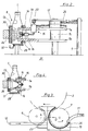
- FIG. 3 Another possibility is indicated in Fig. 3.
- the diameter of the outlet star 7 is larger than that of the inlet star 6.
- the discharge conveyor 11 runs in its initial region tangentially to the outlet star 7 and thus at an acute angle to the feed conveyor 12.
- a relatively long friction and application surface can also be realized in this way, which is completely sufficient for applying the usual liquids to bottles.
- the device 8 on the first outlet star 7 has, in addition to the friction and application element 13, a further essential component the friction and application area from the outside metered with liquid wetting supply line 15.
- Their active elements are spray nozzles 16, which are attached radially outward in height between the star plates 7 a and 7 b and circumferentially between two adjacent pockets 9 on the first outlet star 7. The spray nozzles 16 thus rotate together with the first outlet star 7.
- a spray nozzle 16 is provided after every second pocket 9, which is suitable for many applications. If there is a higher consumption of liquid or a thicker coating, one or more spray nozzles 16 can also be provided after each pocket 9. On the other hand, a spray nozzle 16 can also be provided, for example, only after every third or fourth pocket 9 with low consumption or a smaller layer thickness.
- each spray nozzle 16 is oriented in such a way that it directs a jet which widens out in a fan shape past two adjacent bottles 1 onto the fixed friction and application element 13.
- the jet extends radially outward with respect to the axis of rotation of the first outlet star 7, specifically in a vertical plane passing through the axis of rotation.
- the bottles 1 themselves are therefore not reached by the spray jet.
- the second outlet star 7 rotates, the friction and application surface of each individual spray nozzle 16 is sprayed with liquid essentially over the entire height and over a certain length, ie in the form of a surface.
- the spray jet expediently ends at a short distance from the upper and lower edge of the friction and application surface, so that the spray jet is reliably prevented from going beyond the friction and application element 13.
- Each spray nozzle 16 is connected via a short pipe or hose piece with its own switching valve 19 which is attached to the upper star plate 7 a in such a way that its spring-loaded switching pin protrudes upwards.
- Each switching valve 19 is connected by a further short piece of pipe or hose to a common rotary distributor 17 which is concentric with the first outlet star 7.
- the rotatable part of the rotary distributor 17 is attached to the upper star plate 7 a.
- the fixed part of the rotary distributor 17 is secured against rotation via a horizontal arm 25, which is supported with its free end on a vertical column 5.
- a longer piece of pipe or hose runs from this distributor 25 from the rotary distributor 17 to the closed reservoir 18 for the liquid. From this, the liquid is pushed up and pushed through the spray nozzles 16 by introducing compressed air at an adjustable pressure.
- a fixed control cam 20 for the switching valves 19 is also attached to the arm 25. This is designed as an arcuate stroke curve and projects into the orbit of the switching pins in such a way that they are pressed down in the area of the control curve 20 and thereby release the liquid supply to the spray nozzles 16.
- the control cam 20 begins shortly after the start of the friction and application element 13 and ends approximately after two thirds of its length. Outside the control curve 20, the switching valves 19 are automatically closed under the influence of their spring elements; the liquid supply to the spray nozzles 16 is prevented.
- the friction and application element 13 is made in two parts and only covers the upper and lower edge area of the cylindrical bottle body. Each part of the friction and application element 13 is supplied by its own spray nozzle 16.
- the supply of the liquid to the spray nozzles 16 is initiated by manually or automatically opening a control valve 31 which regulates the compressed air supply to the storage container 18.
- a control valve 31 which regulates the compressed air supply to the storage container 18.
- the spray nozzles 16 standing in the area of the control curve 20 are supplied with liquid under pressure and begin to spray the relevant areas of the friction and application element 13 with liquid. If the labeling machine is still at this point, only parts of the friction and application area are applied. Since, as a result of the closed-pore design, the friction and application element 13 does not store any liquid, it runs downward and is collected in a channel 32 which covers the entire lower edge of the friction and application element 13.
- the control valve 31 is therefore expediently only opened shortly before the first labeled bottles reach the outlet star 7. Automation of this process is extremely simple, since in any case any conventional labeling machine has at least one bottle sensor, through which the label dispensing is controlled. The channel 32 can then also be dispensed with.
- the labeled bottles 1 entering the first outlet star 7 are rotatably received in the pockets 9 thereof by the rollers 14 and continuously rotated by rolling on the stationary friction and application element 13.
- the bottles 1 absorb from the rubbing and application surface the liquid previously applied by the spray nozzles 16 running between the bottles 1, distributed uniformly over the circumference.
- the spray nozzles 16 are already closed, there is another intensive rolling on and, if necessary, squeezing off excess liquid. Layer thicknesses of a few millimeters thick or from a few milligrams of liquid can be achieved without any problems.
- the application and friction element 13 according to FIG. 2 additionally intensively rolls up the body and back labels which are wetted with the liquid plastic or the like. This leads to an extremely advantageous appearance of the finished bottles 1.
Claims (19)
- Procédé d'application d'un liquide sur des bouteilles, dans lequel les bouteilles sont transportées à une distance de pas sur une partie d'une voie de transport, au contact d'un élément d'application au moins, et reçoivent du liquide, dans leur mouvement de rotation, sur une partie au moins de leur surface externe, caractérisé en ce que le liquide est appliqué sur l'elément d'application (13) stationnaire au moyen d'un pulvérisateur (16), au moins, déplacé à distance de l'élément d'application et orienté directement sur ce dernier.
- Dispositif pour l'application d'un liquide sur des bouteilles, avec un dispositif de transport (7) pour les bouteilles, avec un élément d'application (13), au moins, devant lequel les bouteilles sont transportées avec un mouvement de rotation et de contact, et avec une conduite d'arrivée (15) pour l'alimentation en liquide de l'élément d'application, caractérisé en ce que la conduite d'arrivée (15) présente au moins un pulvérisateur (16), disposé à distance et avec une possibilité de déplacement par rapport à l'élément d'application (13), stationnaire, et dirigé directement sur l'élément d'application (13).
- Dispositif suivant la revendication 2, caractérisé en ce que le pulvérisateur (16) est monté sur le dispositif de transport (7).
- Dispositif suivant l'une des revendications 2 et 3, caractérisé en ce que le dispositif de transport est réalisé sous forme de convoyeur en étoile (7), avec des poches (9).
- Dispositif suivant la revendication 4, caractérisé en ce que l'élément d'application (13) est disposé d'une manière stationnaire sur le pourtour du convoyeur en étoile (7), avec une surface d'application en forme d'arc.
- Dispositif suivant l'une des revendications 4 et 5, caractérisé en ce que le pulvérisateur (16) est fixé entre deux poches (9) du convoyeur en étoile (7), et est essentiellement orienté dans le sens radial externe.
- Dispositif suivant les revendications 3 à 6, caractérisé par plusieurs pulvérisateurs (16), régulièrement répartis sur le pourtour du convoyeur en étoile (7).
- Dispositif suivant l'une quelconque des revendications 4 à 7, caractérisé en ce que les pulvérisateurs (16) présentent un orifice de sortie en forme de fente, parallèle à l'axe de rotation du convoyeur en étoile (7).
- Dispositif suivant l'une quelconque des revendications 4 à 8, caractérisé en ce que les pulvérisateurs (16) sont fixés entre deux plaques parallèles (7a, 7b) du convoyeur en étoile (7).
- Dispositif suivant l'une quelconque des revendications 4 à 9, caractérisé en ce que les pulvérisateurs (16) sont raccordés à un réservoir (18) de liquide, par l'intermédiaire d'un distributeur rotatif (17) concentrique à l'axe de rotation du convoyeur en étoile (7).
- Dispositif suivant l'une quelconque des revendications 2 à 10, caractérisé en ce que la conduite d'arrivée (15) présente un dispositif de commande (19, 20), qui alimente les pulvérisateurs (16) uniquement Lors de leur passage devant l'élément d'application (13).
- Dispositif suivant la revendication 10, caractérisé en ce que le dispositif de commande (19, 20) a une réalisation telle, que les pulvérisateurs (16) n'humectent de liquide qu'une zone initiale de l'élément d'application (13).
- Dispositif suivant l'une des revendications 11 et 12, caractérisé en ce qu'une soupape de commande propre (19), ouverte et/ou fermée par une came de commande stationnaire (10), est disposée en amont de chaque pulvérisateur (16).
- Dispositif suivant L'une quelconque des revendications 2 à 13, caractérisé en ce que l'élément d'application (13) sollicite essentiellement la totalité de la zone cylindrique des bouteilles, y compris des zones éventuellement étiquetées, et est humecté de liquide sur la totalité de sa hauteur essentiellement.
- Dispositif suivant la revendication 14, caractérisé en ce que les pulvérisateurs (16) produisent un jet en éventail, pénétrant dans le sens radial externe entre des bouteilles adjacentes.
- Dispositif suivant l'une quelconque des revendications 2 à 15, caractérisé en ce que l'élément d'application (13) présente plusieurs surfaces d'application étroites en forme d'arc, qui sollicitent la zone cylindrique des bouteilles, sur le bord supérieur et inférieur, de préférence.
- Dispositif suivant la revendication 16, caractérisé en ce que chacune des surfaces d'application étroites est humidifiée par un pulvérisateur propre (16), au moins, tournant avec le convoyeur en étoile (7).
- Dispositif suivant l'une quelconque des revendications 2 à 17, caractérisé en ce que l'élément d'application (13) se compose d'un matériau spongieux avec des pores essentiellement fermés.
- Dispositif suivant l'une quelconque au moins des revendications 2 à 18, caractérisé en ce que le convoyeur en étoile est l'étoile de sortie d'une étiqueteuse.
Applications Claiming Priority (2)
| Application Number | Priority Date | Filing Date | Title |
|---|---|---|---|
| DE4012331 | 1990-04-18 | ||
| DE4012331A DE4012331C2 (de) | 1990-04-18 | 1990-04-18 | Etikettiermaschine für Flaschen o. dgl. |
Publications (3)
| Publication Number | Publication Date |
|---|---|
| EP0452943A2 EP0452943A2 (fr) | 1991-10-23 |
| EP0452943A3 EP0452943A3 (en) | 1992-01-02 |
| EP0452943B1 true EP0452943B1 (fr) | 1994-07-13 |
Family
ID=6404571
Family Applications (1)
| Application Number | Title | Priority Date | Filing Date |
|---|---|---|---|
| EP91106257A Expired - Lifetime EP0452943B1 (fr) | 1990-04-18 | 1991-04-18 | Procédé et dispositif pour appliquer un liquide sur des bouteilles |
Country Status (6)
| Country | Link |
|---|---|
| EP (1) | EP0452943B1 (fr) |
| JP (1) | JPH0771967B2 (fr) |
| CA (1) | CA2040705C (fr) |
| DE (2) | DE4012331C2 (fr) |
| DK (1) | DK0452943T3 (fr) |
| ES (1) | ES2057648T3 (fr) |
Families Citing this family (4)
| Publication number | Priority date | Publication date | Assignee | Title |
|---|---|---|---|---|
| DE4427871A1 (de) * | 1994-08-06 | 1996-02-08 | Alfill Getraenketechnik | Vorrichtung zum Beschichten von mit einem Farbaufdruck versehenen Behältern der Getränkeindustrie |
| DE4440393C3 (de) * | 1994-11-11 | 1999-10-21 | Sprimag Spritzmaschbau Gmbh | Vorrichtung zur Beschichtung von rotationssymmetrischen Formkörpern |
| US20040221803A1 (en) * | 2003-03-28 | 2004-11-11 | Eisen Heinz Gunther | Bottle contact coating apparatus and improved sponges for use therein |
| DE102020110136A1 (de) | 2020-04-14 | 2021-10-14 | Krones Aktiengesellschaft | Verfahren und Vorrichtung zum Herstellen von Flaschen mit Scheuerrändern |
Family Cites Families (5)
| Publication number | Priority date | Publication date | Assignee | Title |
|---|---|---|---|---|
| DE2941105C2 (de) * | 1978-10-14 | 1982-04-08 | Kirin Beer K.K. | Verwendung einer Polysiloxanzusammensetzung zum Beschichten von Glasgegenständen, insbesondere zum Abdecken von Kratzern auf Glasflaschen |
| JPS58906B2 (ja) * | 1979-04-09 | 1983-01-08 | 麒麟麦酒株式会社 | 壜等の塗布装置 |
| DE3008096C2 (de) * | 1980-03-03 | 1982-09-23 | Jagenberg-Werke AG, 4000 Düsseldorf | Vorrichtung zum Auftragen einer Kunststoffschicht auf Behälter |
| DE3141364C2 (de) * | 1981-10-17 | 1984-12-20 | Krones Ag Hermann Kronseder Maschinenfabrik, 8402 Neutraubling | Vorrichtung zum Verteilen von aufrechtstehenden Gefäßen |
| CA1234688A (fr) * | 1984-04-27 | 1988-04-05 | Yogiro Okawa | Dispositif d'enduction de la surface eraflee de bouteilles |
-
1990
- 1990-04-18 DE DE4012331A patent/DE4012331C2/de not_active Expired - Fee Related
-
1991
- 1991-04-17 CA CA002040705A patent/CA2040705C/fr not_active Expired - Fee Related
- 1991-04-18 ES ES91106257T patent/ES2057648T3/es not_active Expired - Lifetime
- 1991-04-18 DE DE59102146T patent/DE59102146D1/de not_active Expired - Lifetime
- 1991-04-18 JP JP3086913A patent/JPH0771967B2/ja not_active Expired - Lifetime
- 1991-04-18 EP EP91106257A patent/EP0452943B1/fr not_active Expired - Lifetime
- 1991-04-18 DK DK91106257.8T patent/DK0452943T3/da active
Also Published As
| Publication number | Publication date |
|---|---|
| EP0452943A2 (fr) | 1991-10-23 |
| DK0452943T3 (da) | 1994-09-05 |
| JPH04242532A (ja) | 1992-08-31 |
| ES2057648T3 (es) | 1994-10-16 |
| DE4012331C2 (de) | 1994-02-24 |
| EP0452943A3 (en) | 1992-01-02 |
| DE59102146D1 (de) | 1994-08-18 |
| CA2040705C (fr) | 1995-02-07 |
| JPH0771967B2 (ja) | 1995-08-02 |
| DE4012331A1 (de) | 1991-10-24 |
Similar Documents
| Publication | Publication Date | Title |
|---|---|---|
| DE4105524C2 (fr) | ||
| DE3013442C2 (de) | Maschine zum Beschichten einer Aufeinanderfolge im wesentlichen zylindrischer oder runder Gegenstände mit einer gewünschten Substanz | |
| DE3515324C2 (fr) | ||
| EP0275887B1 (fr) | Dispositif pour appliquer de la colle sur des ébauches d'emballage | |
| EP2111359B1 (fr) | Groupe d'étiquetage | |
| DE3724196A1 (de) | Vorrichtung zum auftragen von loesungsmitteln und dergleichen | |
| EP2229324A1 (fr) | Procédé d'étiquetage de récipients et poste d'étiquetage | |
| DE3008096C2 (de) | Vorrichtung zum Auftragen einer Kunststoffschicht auf Behälter | |
| DE2642046C3 (de) | Etikettiervorrichtung für Gefäße | |
| DE2152048A1 (de) | Vorrichtung zur Aufbringung von Klebstoff auf Etiketten und zur Verteilung dieser Etiketten | |
| EP0452943B1 (fr) | Procédé et dispositif pour appliquer un liquide sur des bouteilles | |
| DE102004029788A1 (de) | Vorrichtung zum Etikettieren von Gefäßen | |
| DE973404C (de) | Maschine zum Etikettieren von Flaschen oder anderen zylindrischen Gegenstaenden | |
| EP1423212B1 (fr) | Dispositif pour appliquer des lubrifiants sur la surface peripherique de cylindres dans des cages de laminoir | |
| DE19821253B4 (de) | Etikettiermaschine | |
| DE3149886A1 (de) | Etikettiermaschine fuer gegenstaende, wie flaschen | |
| DE1164312B (de) | Etikettiermaschine | |
| DE19811542C2 (de) | Etikettiermaschine | |
| DE1586388A1 (de) | Vorrichtung zum Stanniolieren von Flaschen | |
| DE19927630A1 (de) | Behälteretikettiervorrichtung mit Befeuchtungseinrichtung | |
| DE1253143B (de) | Anwendung einer ueblichen Etikettiermaschine zum Aufbringen von Glasmustern in Form von Abziehbildern auf Glas- bzw. Keramikgegenstaende, insbesondere Flaschen | |
| DE1022150B (de) | Etikettiermaschine fuer aufrecht stehende Flaschen | |
| DE2504647A1 (de) | Lackiermaschine | |
| DE20316359U1 (de) | Vorrichtung zum Anbringen von Steuerstreifen oder Banderolen an Behältern | |
| DE19811522A1 (de) | Etikettiermaschine |
Legal Events
| Date | Code | Title | Description |
|---|---|---|---|
| PUAI | Public reference made under article 153(3) epc to a published international application that has entered the european phase |
Free format text: ORIGINAL CODE: 0009012 |
|
| AK | Designated contracting states |
Kind code of ref document: A2 Designated state(s): BE DE DK ES FR GB IT NL SE |
|
| PUAL | Search report despatched |
Free format text: ORIGINAL CODE: 0009013 |
|
| AK | Designated contracting states |
Kind code of ref document: A3 Designated state(s): BE DE DK ES FR GB IT NL SE |
|
| 17P | Request for examination filed |
Effective date: 19911204 |
|
| 17Q | First examination report despatched |
Effective date: 19930330 |
|
| GRAA | (expected) grant |
Free format text: ORIGINAL CODE: 0009210 |
|
| ITF | It: translation for a ep patent filed |
Owner name: PATRITO BREVETTI |
|
| AK | Designated contracting states |
Kind code of ref document: B1 Designated state(s): BE DE DK ES FR GB IT NL SE |
|
| ET | Fr: translation filed | ||
| REF | Corresponds to: |
Ref document number: 59102146 Country of ref document: DE Date of ref document: 19940818 |
|
| REG | Reference to a national code |
Ref country code: DK Ref legal event code: T3 |
|
| GBT | Gb: translation of ep patent filed (gb section 77(6)(a)/1977) |
Effective date: 19940808 |
|
| REG | Reference to a national code |
Ref country code: ES Ref legal event code: FG2A Ref document number: 2057648 Country of ref document: ES Kind code of ref document: T3 |
|
| EAL | Se: european patent in force in sweden |
Ref document number: 91106257.8 |
|
| PLBE | No opposition filed within time limit |
Free format text: ORIGINAL CODE: 0009261 |
|
| STAA | Information on the status of an ep patent application or granted ep patent |
Free format text: STATUS: NO OPPOSITION FILED WITHIN TIME LIMIT |
|
| 26N | No opposition filed | ||
| REG | Reference to a national code |
Ref country code: GB Ref legal event code: IF02 |
|
| PGFP | Annual fee paid to national office [announced via postgrant information from national office to epo] |
Ref country code: SE Payment date: 20020423 Year of fee payment: 12 |
|
| PG25 | Lapsed in a contracting state [announced via postgrant information from national office to epo] |
Ref country code: SE Free format text: LAPSE BECAUSE OF NON-PAYMENT OF DUE FEES Effective date: 20030419 |
|
| EUG | Se: european patent has lapsed | ||
| PGFP | Annual fee paid to national office [announced via postgrant information from national office to epo] |
Ref country code: ES Payment date: 20040412 Year of fee payment: 14 |
|
| PGFP | Annual fee paid to national office [announced via postgrant information from national office to epo] |
Ref country code: BE Payment date: 20040427 Year of fee payment: 14 |
|
| PG25 | Lapsed in a contracting state [announced via postgrant information from national office to epo] |
Ref country code: ES Free format text: LAPSE BECAUSE OF NON-PAYMENT OF DUE FEES Effective date: 20050419 |
|
| PG25 | Lapsed in a contracting state [announced via postgrant information from national office to epo] |
Ref country code: BE Free format text: LAPSE BECAUSE OF NON-PAYMENT OF DUE FEES Effective date: 20050430 |
|
| BERE | Be: lapsed |
Owner name: *KRONES A.G. HERMANN KRONSEDER MASCHINENFABRIK Effective date: 20050430 |
|
| PGFP | Annual fee paid to national office [announced via postgrant information from national office to epo] |
Ref country code: GB Payment date: 20060322 Year of fee payment: 16 |
|
| REG | Reference to a national code |
Ref country code: ES Ref legal event code: FD2A Effective date: 20050419 |
|
| GBPC | Gb: european patent ceased through non-payment of renewal fee |
Effective date: 20070418 |
|
| BERE | Be: lapsed |
Owner name: *KRONES A.G. HERMANN KRONSEDER MASCHINENFABRIK Effective date: 20050430 |
|
| PG25 | Lapsed in a contracting state [announced via postgrant information from national office to epo] |
Ref country code: GB Free format text: LAPSE BECAUSE OF NON-PAYMENT OF DUE FEES Effective date: 20070418 |
|
| PGFP | Annual fee paid to national office [announced via postgrant information from national office to epo] |
Ref country code: DK Payment date: 20100412 Year of fee payment: 20 Ref country code: FR Payment date: 20100521 Year of fee payment: 20 |
|
| PGFP | Annual fee paid to national office [announced via postgrant information from national office to epo] |
Ref country code: NL Payment date: 20100402 Year of fee payment: 20 Ref country code: DE Payment date: 20100430 Year of fee payment: 20 Ref country code: IT Payment date: 20100423 Year of fee payment: 20 |
|
| REG | Reference to a national code |
Ref country code: DE Ref legal event code: R071 Ref document number: 59102146 Country of ref document: DE |
|
| REG | Reference to a national code |
Ref country code: NL Ref legal event code: V4 Effective date: 20110418 |
|
| REG | Reference to a national code |
Ref country code: DK Ref legal event code: EUP |
|
| PG25 | Lapsed in a contracting state [announced via postgrant information from national office to epo] |
Ref country code: NL Free format text: LAPSE BECAUSE OF EXPIRATION OF PROTECTION Effective date: 20110418 |
|
| PG25 | Lapsed in a contracting state [announced via postgrant information from national office to epo] |
Ref country code: DE Free format text: LAPSE BECAUSE OF EXPIRATION OF PROTECTION Effective date: 20110418 |