EP0452943B1 - Method and device for applying a liquid onto bottles - Google Patents
Method and device for applying a liquid onto bottles Download PDFInfo
- Publication number
- EP0452943B1 EP0452943B1 EP91106257A EP91106257A EP0452943B1 EP 0452943 B1 EP0452943 B1 EP 0452943B1 EP 91106257 A EP91106257 A EP 91106257A EP 91106257 A EP91106257 A EP 91106257A EP 0452943 B1 EP0452943 B1 EP 0452943B1
- Authority
- EP
- European Patent Office
- Prior art keywords
- bottles
- liquid
- applicator element
- star
- star conveyor
- Prior art date
- Legal status (The legal status is an assumption and is not a legal conclusion. Google has not performed a legal analysis and makes no representation as to the accuracy of the status listed.)
- Expired - Lifetime
Links
- 239000007788 liquid Substances 0.000 title claims description 54
- 238000000034 method Methods 0.000 title claims description 7
- 239000007921 spray Substances 0.000 claims description 38
- 238000002372 labelling Methods 0.000 claims description 21
- 239000011148 porous material Substances 0.000 claims description 4
- 239000000463 material Substances 0.000 claims description 3
- 238000003860 storage Methods 0.000 claims description 2
- 229920003023 plastic Polymers 0.000 description 5
- 239000004033 plastic Substances 0.000 description 5
- 239000011248 coating agent Substances 0.000 description 3
- 238000000576 coating method Methods 0.000 description 3
- 239000011521 glass Substances 0.000 description 3
- 238000005096 rolling process Methods 0.000 description 3
- 230000001680 brushing effect Effects 0.000 description 2
- 239000003795 chemical substances by application Substances 0.000 description 2
- 239000010408 film Substances 0.000 description 2
- 239000006260 foam Substances 0.000 description 2
- 238000004519 manufacturing process Methods 0.000 description 2
- 235000011837 pasties Nutrition 0.000 description 2
- 229920001084 poly(chloroprene) Polymers 0.000 description 2
- 230000001681 protective effect Effects 0.000 description 2
- 238000011144 upstream manufacturing Methods 0.000 description 2
- 230000001154 acute effect Effects 0.000 description 1
- 230000006978 adaptation Effects 0.000 description 1
- 210000000481 breast Anatomy 0.000 description 1
- 230000001419 dependent effect Effects 0.000 description 1
- 238000011161 development Methods 0.000 description 1
- 230000018109 developmental process Effects 0.000 description 1
- KPUWHANPEXNPJT-UHFFFAOYSA-N disiloxane Chemical class [SiH3]O[SiH3] KPUWHANPEXNPJT-UHFFFAOYSA-N 0.000 description 1
- 230000000694 effects Effects 0.000 description 1
- 239000013013 elastic material Substances 0.000 description 1
- 239000000945 filler Substances 0.000 description 1
- 239000012530 fluid Substances 0.000 description 1
- 235000015073 liquid stocks Nutrition 0.000 description 1
- 238000005496 tempering Methods 0.000 description 1
- 239000010409 thin film Substances 0.000 description 1
- 238000009736 wetting Methods 0.000 description 1
Images

Classifications
-
- B—PERFORMING OPERATIONS; TRANSPORTING
- B65—CONVEYING; PACKING; STORING; HANDLING THIN OR FILAMENTARY MATERIAL
- B65C—LABELLING OR TAGGING MACHINES, APPARATUS, OR PROCESSES
- B65C9/00—Details of labelling machines or apparatus
- B65C9/20—Gluing the labels or articles
- B65C9/22—Gluing the labels or articles by wetting, e.g. by applying liquid glue or a liquid to a dry glue coating
- B65C9/2204—Gluing the labels or articles by wetting, e.g. by applying liquid glue or a liquid to a dry glue coating using spraying means
-
- B—PERFORMING OPERATIONS; TRANSPORTING
- B05—SPRAYING OR ATOMISING IN GENERAL; APPLYING FLUENT MATERIALS TO SURFACES, IN GENERAL
- B05C—APPARATUS FOR APPLYING FLUENT MATERIALS TO SURFACES, IN GENERAL
- B05C1/00—Apparatus in which liquid or other fluent material is applied to the surface of the work by contact with a member carrying the liquid or other fluent material, e.g. a porous member loaded with a liquid to be applied as a coating
- B05C1/02—Apparatus in which liquid or other fluent material is applied to the surface of the work by contact with a member carrying the liquid or other fluent material, e.g. a porous member loaded with a liquid to be applied as a coating for applying liquid or other fluent material to separate articles
- B05C1/027—Apparatus in which liquid or other fluent material is applied to the surface of the work by contact with a member carrying the liquid or other fluent material, e.g. a porous member loaded with a liquid to be applied as a coating for applying liquid or other fluent material to separate articles only at particular parts of the articles
-
- B—PERFORMING OPERATIONS; TRANSPORTING
- B05—SPRAYING OR ATOMISING IN GENERAL; APPLYING FLUENT MATERIALS TO SURFACES, IN GENERAL
- B05C—APPARATUS FOR APPLYING FLUENT MATERIALS TO SURFACES, IN GENERAL
- B05C1/00—Apparatus in which liquid or other fluent material is applied to the surface of the work by contact with a member carrying the liquid or other fluent material, e.g. a porous member loaded with a liquid to be applied as a coating
- B05C1/04—Apparatus in which liquid or other fluent material is applied to the surface of the work by contact with a member carrying the liquid or other fluent material, e.g. a porous member loaded with a liquid to be applied as a coating for applying liquid or other fluent material to work of indefinite length
- B05C1/06—Apparatus in which liquid or other fluent material is applied to the surface of the work by contact with a member carrying the liquid or other fluent material, e.g. a porous member loaded with a liquid to be applied as a coating for applying liquid or other fluent material to work of indefinite length by rubbing contact, e.g. by brushes, by pads
-
- B—PERFORMING OPERATIONS; TRANSPORTING
- B05—SPRAYING OR ATOMISING IN GENERAL; APPLYING FLUENT MATERIALS TO SURFACES, IN GENERAL
- B05C—APPARATUS FOR APPLYING FLUENT MATERIALS TO SURFACES, IN GENERAL
- B05C1/00—Apparatus in which liquid or other fluent material is applied to the surface of the work by contact with a member carrying the liquid or other fluent material, e.g. a porous member loaded with a liquid to be applied as a coating
- B05C1/02—Apparatus in which liquid or other fluent material is applied to the surface of the work by contact with a member carrying the liquid or other fluent material, e.g. a porous member loaded with a liquid to be applied as a coating for applying liquid or other fluent material to separate articles
- B05C1/022—Apparatus in which liquid or other fluent material is applied to the surface of the work by contact with a member carrying the liquid or other fluent material, e.g. a porous member loaded with a liquid to be applied as a coating for applying liquid or other fluent material to separate articles to the outer surface of hollow articles
Definitions
- the invention relates to a method and a device for applying a liquid to bottles according to the preamble of claims 1 and 2 respectively.
- Reusable bottles made of glass, plastic, etc. often become unsightly after several cycles due to the heavy use in the bottling plants and during transport to and from the consumer.
- chafing spots as well as other chips and scratches are preferably formed in the upper and lower edge region of the cylindrical bottle body.
- a thin film of liquid plastic for example a siloxane, is applied to the reusable bottles, which largely covers the scratches and chafe marks and gives the bottles a new appearance (DE-OS 29 41 105).
- the object of the invention is to solve this problem and to improve a method and a device for applying liquids of the type mentioned in such a way that a wide variety of types of liquids with low liquid consumption could be applied evenly.
- claim 19 describes an advantageous arrangement of the device according to the invention, the device being part of the outlet star of a labeling machine there.
- the device according to the invention can be used equally at various points, independently of upstream or downstream fillers or labeling machines, in order to apply liquid to bottles.
- the invention is described below in a special application, where this device is part of a labeling machine and is integrated in the outlet star of the labeling machine.
- This labeling machine is set up for labeling and subsequent coating of upright bottles 1, namely reusable glass bottles with a liquid, namely with a liquid plastic for covering chafing spots.
- This coating device is implemented in the star conveyor 7, which is referred to below as the discharge star.
- the labeling machine has a box-like housing 21 in which a drive motor, not shown, is accommodated.
- a turntable 2 with an upstream inlet star 6 and the star conveyor 7 designed as an outlet star and the outlet star 10 are rotatably supported about vertical axes.
- the inlet star 6 is preceded by an inlet screw 22 which can be rotated about a horizontal axis and which brings the bottles 1, which are transported to the labeling machine on a horizontal conveyor belt 12, at a distance and transfers them to the inlet star 6 in accordance with the division.
- the bottles 1 are held by a stationary inlet bend 23 and then run onto the turntable 2, where they are fixed on controllable turntables (not shown) by means of lifting and lowering centering bells, not shown.
- the bottles 1 are then transferred from the turntable 2 to the first outlet star 7, on the circumference of which a stationary outlet arch 24 is arranged.
- the second outlet star 10 takes over the bottles 1 from the first outlet star 7 and places them on a horizontal conveyor belt 11, through which the bottles are transported away from the labeling machine.
- the discharge conveyor belt 11 and on the circumference of the second outlet star 10 the bottles are guided through appropriately arranged fixed railings 26.
- the bottles stand on stationary slide plates 29.
- the conveyor elements 2, 6, 7, 10 and 22 and the conveyor belts 11 and 12 are driven synchronously with one another and continuously in the direction of the arrow by the drive motor of the labeling machine, so that the bottles 1 can be transported precisely and gently even at high outputs.
- two conventional labeling stations 3 and 4 are also arranged which, with their rotating gripper cylinders 27, affect the orbit of the bottles 1 on the rotary table 2 and are driven synchronously with the rotary table 2 by the drive motor of the labeling machine.
- the bottles 1 are provided with a body label and a breast label, which are firmly nestled to the bottles in a subsequent brushing station 28 with brushes and sponge rollers, not shown.
- the bottles 1 are provided with a back label by the second labeling station 4, which is pressed onto the bottles in a further subsequent brushing station 28 with brushes and sponge rollers (not shown). Then the fully labeled bottles 1 run into the first outlet star 7.
- the first outlet star 7 has an upper star plate 7 a and a lower star plate 7 b.
- the two star plates 7 a and 7 b are fixed parallel to each other at a distance on a common hub 7 c.
- freely rotatable rollers 14 with axes parallel to the axis of rotation of the outlet star 7 are each mounted in the front and rear region of each pocket 9. The rollers 14 engage on the lowermost or uppermost area of the cylindrical bottle body and thus on the one hand enable an exact, division-appropriate transport and on the other hand an effortless rotation of the bottles 1 in the first outlet star 7.
- the first outlet star 7 is assigned the device 8 for applying the liquid to the finished labeled bottles 1 which are moved in its pockets 9 on a circular arc path.
- This device 8 has a fixed friction and application element 13, which is arranged concentrically to the outlet star 7 and has an arcuate, more precisely partially cylindrical, friction and application surface.
- the friction and application element 13 consists of a closed-pore neoprene foam which is placed on a partially cylindrical support plate 30 is glued on. The support plate 30 is in turn attached in a vertical position to the stationary outlet arch 24.
- the arrangement is such that the bottles 1 located in the pockets 9 of the first discharge star 7 easily press into the neoprene foam of the friction and application element 13 and therefore come into frictional contact therewith. When the spout 7 rotates, the bottles 1 are therefore set to self-rotation continuously by means of the friction and application element 13.
- the bottles 1 are moved in the first outlet star over an angular range of approximately 270 degrees, the outlet star 7 having the same diameter as the inlet star 6.
- This relatively large angular range which is the case with the usual bottle and star diameters
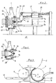
- FIG. 3 Another possibility is indicated in Fig. 3.
- the diameter of the outlet star 7 is larger than that of the inlet star 6.
- the discharge conveyor 11 runs in its initial region tangentially to the outlet star 7 and thus at an acute angle to the feed conveyor 12.
- a relatively long friction and application surface can also be realized in this way, which is completely sufficient for applying the usual liquids to bottles.
- the device 8 on the first outlet star 7 has, in addition to the friction and application element 13, a further essential component the friction and application area from the outside metered with liquid wetting supply line 15.
- Their active elements are spray nozzles 16, which are attached radially outward in height between the star plates 7 a and 7 b and circumferentially between two adjacent pockets 9 on the first outlet star 7. The spray nozzles 16 thus rotate together with the first outlet star 7.
- a spray nozzle 16 is provided after every second pocket 9, which is suitable for many applications. If there is a higher consumption of liquid or a thicker coating, one or more spray nozzles 16 can also be provided after each pocket 9. On the other hand, a spray nozzle 16 can also be provided, for example, only after every third or fourth pocket 9 with low consumption or a smaller layer thickness.
- each spray nozzle 16 is oriented in such a way that it directs a jet which widens out in a fan shape past two adjacent bottles 1 onto the fixed friction and application element 13.
- the jet extends radially outward with respect to the axis of rotation of the first outlet star 7, specifically in a vertical plane passing through the axis of rotation.
- the bottles 1 themselves are therefore not reached by the spray jet.
- the second outlet star 7 rotates, the friction and application surface of each individual spray nozzle 16 is sprayed with liquid essentially over the entire height and over a certain length, ie in the form of a surface.
- the spray jet expediently ends at a short distance from the upper and lower edge of the friction and application surface, so that the spray jet is reliably prevented from going beyond the friction and application element 13.
- Each spray nozzle 16 is connected via a short pipe or hose piece with its own switching valve 19 which is attached to the upper star plate 7 a in such a way that its spring-loaded switching pin protrudes upwards.
- Each switching valve 19 is connected by a further short piece of pipe or hose to a common rotary distributor 17 which is concentric with the first outlet star 7.
- the rotatable part of the rotary distributor 17 is attached to the upper star plate 7 a.
- the fixed part of the rotary distributor 17 is secured against rotation via a horizontal arm 25, which is supported with its free end on a vertical column 5.
- a longer piece of pipe or hose runs from this distributor 25 from the rotary distributor 17 to the closed reservoir 18 for the liquid. From this, the liquid is pushed up and pushed through the spray nozzles 16 by introducing compressed air at an adjustable pressure.
- a fixed control cam 20 for the switching valves 19 is also attached to the arm 25. This is designed as an arcuate stroke curve and projects into the orbit of the switching pins in such a way that they are pressed down in the area of the control curve 20 and thereby release the liquid supply to the spray nozzles 16.
- the control cam 20 begins shortly after the start of the friction and application element 13 and ends approximately after two thirds of its length. Outside the control curve 20, the switching valves 19 are automatically closed under the influence of their spring elements; the liquid supply to the spray nozzles 16 is prevented.
- the friction and application element 13 is made in two parts and only covers the upper and lower edge area of the cylindrical bottle body. Each part of the friction and application element 13 is supplied by its own spray nozzle 16.
- the supply of the liquid to the spray nozzles 16 is initiated by manually or automatically opening a control valve 31 which regulates the compressed air supply to the storage container 18.
- a control valve 31 which regulates the compressed air supply to the storage container 18.
- the spray nozzles 16 standing in the area of the control curve 20 are supplied with liquid under pressure and begin to spray the relevant areas of the friction and application element 13 with liquid. If the labeling machine is still at this point, only parts of the friction and application area are applied. Since, as a result of the closed-pore design, the friction and application element 13 does not store any liquid, it runs downward and is collected in a channel 32 which covers the entire lower edge of the friction and application element 13.
- the control valve 31 is therefore expediently only opened shortly before the first labeled bottles reach the outlet star 7. Automation of this process is extremely simple, since in any case any conventional labeling machine has at least one bottle sensor, through which the label dispensing is controlled. The channel 32 can then also be dispensed with.
- the labeled bottles 1 entering the first outlet star 7 are rotatably received in the pockets 9 thereof by the rollers 14 and continuously rotated by rolling on the stationary friction and application element 13.
- the bottles 1 absorb from the rubbing and application surface the liquid previously applied by the spray nozzles 16 running between the bottles 1, distributed uniformly over the circumference.
- the spray nozzles 16 are already closed, there is another intensive rolling on and, if necessary, squeezing off excess liquid. Layer thicknesses of a few millimeters thick or from a few milligrams of liquid can be achieved without any problems.
- the application and friction element 13 according to FIG. 2 additionally intensively rolls up the body and back labels which are wetted with the liquid plastic or the like. This leads to an extremely advantageous appearance of the finished bottles 1.
Description
Die Erfindung betrifft ein Verfahren und eine Vorrichtung zum Auftragen einer Flüssigkeit auf Flaschen entsprechend dem Oberbegriff des Anspruchs 1 bzw. 2.2. The invention relates to a method and a device for applying a liquid to bottles according to the preamble of
Mehrwegflaschen aus Glas, Kunststoff usw. werden nach mehreren Umläufen infolge der starken Beanspruchung in den Abfüllanlagen sowie auf dem Transport zum und vom Verbraucher häufig rasch unansehlich. Insbesondere durch das Aneinanderschlagen in den Abfüllanlagen bilden sich bevorzugt im oberen und unteren Randbereich des zylindrischen Flaschenrumpfes Scheuerstellen sowie sonstige Absplitterungen und Kratzer. In manchen Abfüllbetrieben wird daher auf die Mehrwegflaschen ein dünner Film aus flüssigem Kunststoff, z.B. einem Siloxan, aufgebracht, der die Kratzer und Scheuerstellen weitgehend abdeckt und den Flaschen ein neuwertiges Erscheinungsbild verleiht (DE-OS 29 41 105). Auch wurde bereits vorgeschlagen, die Mehrwegflaschen bei jedem Durchlauf in der Abfüllanlage mit einem flüssigen Kaltendvergütungsmittel zu benetzen, wie es ähnlich in der Glashütte auf die Flaschen aufgebracht wird. Dadurch soll der von der Glasherstellung herrührende Schutzfilm wieder aufgefrischt bzw. aufrechterhalten werden. Schließlich ist es bekannt, auf Flaschen einen Farbfilm aufzutragen sowie flüssige oder pastöse Kunststoffe als Schutzmantel und zur Erhöhung der Stabilität. Alle diese sowie weitere flüssige oder pastöse Mittel, die zum Auftragen auf die Oberfläche von Flaschen oder dergl. geeignet sind, werden im Nachstehenden der Einfachheit halber mit "Flüssigkeit" bezeichnet.Reusable bottles made of glass, plastic, etc. often become unsightly after several cycles due to the heavy use in the bottling plants and during transport to and from the consumer. In particular as a result of striking one another in the bottling plants, chafing spots as well as other chips and scratches are preferably formed in the upper and lower edge region of the cylindrical bottle body. In some filling companies, therefore, a thin film of liquid plastic, for example a siloxane, is applied to the reusable bottles, which largely covers the scratches and chafe marks and gives the bottles a new appearance (DE-OS 29 41 105). It has also already been proposed to wet the reusable bottles with a liquid cold-end tempering agent, as is similarly applied to the bottles in the glassworks, with each pass in the filling system. This is intended to refresh or maintain the protective film originating from glass production. Finally, it is known to apply a color film to bottles as well as liquid or pasty plastics as a protective jacket and to increase stability. All of these as well as other liquid ones or pasty agents suitable for application to the surface of bottles or the like are hereinafter referred to as "liquid" for the sake of simplicity.
Zum Auftragen von Flüssigkeiten auf Flaschen sind bereits spezielle Maschinen mit einem eigenen Antrieb und einem die Flaschen auf einer Kreisbogenbahn bewegenden Transportstern bekannt geworden (BE-PS 882 671; GB-A-20 47 578). Die Flaschen im Transportstern werden durch Abwälzen auf einem feststehenden Reibsegment in Eigenrotation versetzt und durch mit dem Transportstern umlaufende Rollen oder Gleitschuhe aus elastischem Material beaufschlagt, die mittels einer Zuführeinrichtung fortlaufend mit der Flüssigkeit benetzt werden. Diese bekannten, die Gattung bildenden Maschinen, mit denen in der Regel nicht etikettierte Flaschen behandelt werden, können von ihrer Auftragswirkung her durchaus befriedigen. Allerdings hat sich herausgestellt, daß man relativ viel Flüssigkeit zuführen muß, um eine befriedigende Übergabe von den Zuführleitungen auf die Auftragselemente zu bewirken und um sicherzustellen, daß die aufgenommene Flüssigkeit mengenmäßig vor der nächsten erneuten Benetzung so ausreicht, daß ein gleichmäßiger Übertrag auf die Flaschen erfolgen kann. Dabei wird im allgemeinen in den Auftragselementen eine große Flüssigkeitsmenge aufgesaugt, die dann durch Anlage der Flaschen wieder herausgepreßt wird und nach unten abfließt.For the application of liquids to bottles, special machines with their own drive and a transport star moving the bottles on a circular arc path have already become known (BE-PS 882 671; GB-A-20 47 578). The bottles in the transport star are set to self-rotation by rolling on a fixed friction segment and acted upon by rollers or sliding shoes made of elastic material rotating with the transport star, which are continuously wetted with the liquid by means of a feed device. These known, generic machines, with which unlabelled bottles are generally treated, can be quite satisfactory in terms of their application effect. However, it has been found that a relatively large amount of liquid has to be supplied in order to achieve a satisfactory transfer from the supply lines to the application elements and to ensure that the quantity of liquid absorbed is sufficient before the next rewetting so that it is evenly transferred to the bottles can. In this case, a large amount of liquid is generally sucked up in the application elements, which is then pressed out again by contacting the bottles and flows off downwards.
Schließlich ist es aus der US-A-4 586 458 bekannt, die Flüssigkeit von einer sich relativ zu einem Auftragselement bewegenden Spritzdüse mittels zwischen rollen zu übertragen.Finally, it is known from US-A-4,586,458 to transfer the liquid from a spray nozzle moving relative to an application element by means of intermediate rollers.
Aufgabe der Erfindung ist es, dieses Problem zu lösen und ein Verfahren und eine Vorrichtung zum Auftragen für Flüssigkeiten der eingangs genannten Art so zu verbessern, daß verschiedenste Arten von Flüssigkeiten mit geringem Flüssigkeitsverbrauch gleichmäßig aufgetragen werden könnten.The object of the invention is to solve this problem and to improve a method and a device for applying liquids of the type mentioned in such a way that a wide variety of types of liquids with low liquid consumption could be applied evenly.
Gelöst wird diese Aufgabe mit dem im Anspruch 1 angegebenen Verfahren sowie mit der im Anspruch 2 angegebenen Vorrichtung, mit der man dieses Verfahren durchführen kann.This object is achieved with the method specified in claim 1 and with the device specified in
Durch das Auftragen der Flüssigkeit mit Sprühdüsen, die sich zumindestens zum Teil über die Auftragselemente beabstandet zu diesen bewegen, ist es möglich, in sehr dünnen Schichten mit geringen Flüssigkeitsmengen die Flüssigkeit unmittelbar vor Übernahme der Flüssigkeit auf die Flaschen aufzutragen. Dadurch ist es nicht erforderlich, daß die Auftragselemente übermäßige Flüssigkeitsvorräte speichern müssen. Dies führt zu einer Reduzierung des Flüssigkeitsverbrauchs.By applying the liquid with spray nozzles, which at least partly move at a distance from the application elements, it is possible to apply the liquid to the bottles in very thin layers with small amounts of liquid immediately before the liquid is taken over. As a result, it is not necessary for the application elements to have to store excessive liquid stocks. This leads to a reduction in fluid consumption.
Die abhängigen Ansprüche geben vorteilhafte Weiterbildungen der Erfindung wieder.The dependent claims reflect advantageous developments of the invention.
Durch die Verwendung der Spritzdüsen und entsprechende Ausbildung der Auftragsfläche ist ein vollflächiges Auftragen der Flüssigkeit auf den zylindrischen Flaschenrumpf gemäß Anspruch 14 sowie auch ein gezieltes Auftragen auf die für Scheuerstellen besonders anfälligen oberen und unteren Bereiche des Flaschenrumpfes gemäß Anspruch 16 möglich. Dadurch, daß die Flüssigkeit durch die umlaufenden Düsen direkt auf die Außenseite der Auftragselemente bzw. der dadurch gebildeten Auftragsfläche aufgetragen wird, kann diese gemäß Anspruch 18 aus einem schwammartigen Material mit überwiegend geschlossenen Poren bestehen. Dadurch kann sich das Auftragselement nicht mit Flüssigkeit vollsaugen, die ungenutzt an der Unterseite abtropfen würde.Through the use of the spray nozzles and the corresponding design of the application area, a full-area application of the liquid to the cylindrical bottle body according to
Im Anspruch 19 ist schließlich eine vorteilhafte Anordnung der erfindungsgemäßen Vorrichtung beschrieben, wobei die Vorrichtung dort Teil des Auslaufsterns einer Etikettiermaschine ist.Finally,
Nachstehend werden Ausführungsbeispiele der Erfindung anhand der Zeichnung beschrieben. Dabei zeigt
- Figur 1
- eine im Auslaufstern einer Etikettiermaschine integrierte Vorrichtung nach der Erfindung,
Figur 2- den Schnitt A-B nach Figur 1,
Figur 3- eine teilweise Draufsicht auf die Etikettiermaschine mit der erfindungsgemäßen Vorrichtung und
Figur 4- den Schnitt C-D nach
Figur 3.
- Figure 1
- a device according to the invention integrated in the outlet star of a labeling machine,
- Figure 2
- the section AB of Figure 1,
- Figure 3
- a partial plan view of the labeling machine with the device according to the invention and
- Figure 4
- the section CD of Figure 3.
Es ist zunächst darauf hinzuweisen, daß die erfindungsgemäße Vorrichtung an diversen Stellen unabhängig von vor- oder nachgeschalteten Füllern oder Etikettiermaschinen gleichermaßen anwendbar ist, um Flüssigkeit auf Flaschen aufzutragen. Nachfolgend wird die Erfindung in einem speziellen Anwendungsfall beschrieben, wobei diese Vorrichtung dort Teil einer Etikettiermaschine ist und im Auslaufstern der Etikettiermaschine integriert ist.It should first be pointed out that the device according to the invention can be used equally at various points, independently of upstream or downstream fillers or labeling machines, in order to apply liquid to bottles. The invention is described below in a special application, where this device is part of a labeling machine and is integrated in the outlet star of the labeling machine.
Diese Etikettiermaschine nach den Figuren 1 und 2 ist zum Etikettieren und anschließenden Beschichten von aufrechtstehenden Flaschen 1, nämlich Mehrwegflaschen aus Glas mit einer Flüssigkeit, nämlich mit einem flüssigem Kunststoff zum Abdecken von Scheuerstellen, eingerichtet. Diese Beschichtungsvorrichtung ist in dem im folgenden als Auslaufstern bezeichneten Sternförderer 7 verwirklicht.This labeling machine according to FIGS. 1 and 2 is set up for labeling and subsequent coating of upright bottles 1, namely reusable glass bottles with a liquid, namely with a liquid plastic for covering chafing spots. This coating device is implemented in the
Die Etikettiermaschine weist ein kastenartiges Gehäuse 21 auf, in dem ein nicht gezeigter Antriebsmotor untergebracht ist. Auf dem Gehäuse 21 sind ein Drehtisch 2 mit einem vorgeschalteten Einlaufstern 6 und dem als Auslaufstern ausgebildeten Sternförderer 7 sowie dem Auslaufstern 10 um jeweils senkrechte Achsen drehbar gelagert.The labeling machine has a box-
Dem Einlaufstern 6 ist eine um eine horizontale Achse drehbare Einlaufschnecke 22 vorgeordnet, welche die auf einem horizontalen Zuförderband 12 zur Etikettiermaschine transportierten Flaschen 1 auf Abstand bringt und teilungsgerecht an den Einlaufstern 6 übergibt. In dessen Taschen 9 werden die Flaschen 1 durch einen ortsfesten Einlaufbogen 23 gehalten und laufen dann auf den Drehtisch 2, wo sie durch nicht gezeigte heb- und senkbare Zentrierglocken auf gleichfalls nicht gezeigten steuerbaren Drehtellern fixiert werden. Vom Drehtisch 2 werden die Flaschen 1 dann an den ersten Auslaufstern 7 übergeben, an dessen Umfang ein ortsfester Auslaufbogen 24 angeordnet ist. Der zweite Auslaufstern 10 übernimmt die Flaschen 1 vom ersten Auslaufstern 7 und stellt sie auf einem horizontalen Abförderband 11 ab, durch welches die Flaschen von der Etikettiermaschine wegtransportiert werden. Auf dem Zuförderband 12, dem Abförderband 11 sowie am Umfang des zweiten Auslaufsterns 10 werden die Flaschen durch entsprechend angeordnete ortsfeste Geländer 26 geführt. Im Bereich der Sterne 6, 7 und 10 stehen die Flaschen auf ortsfesten Überschubblechen 29. Die Förderelemente 2, 6, 7, 10 und 22 sowie die Förderbänder 11 und 12 werden durch den Antriebsmotor der Etikettiermaschine synchron zueinander und kontinuierlich in Pfeilrichtig angetrieben, so daß die Flaschen 1 positionsgenau und auch bei hohen Leistungen schonend transportiert werden können.The
Auf dem Gehäuse 21 sind ferner zwei herkömmliche Etikettierstationen 3 und 4 angeordnet, die mit ihren rotierenden Greiferzylindern 27 die Umlaufbahn der Flaschen 1 auf dem Drehtisch 2 tangieren und durch den Antriebsmotor der Etikettiermaschine synchron zum Drehtisch 2 angetrieben werden.On the
Durch die erste Etikettierstation 3 werden die Flaschen 1 mit einem Rumpf- und einem Brustetikett versehen, die in einer nachfolgenden Anbürststation 28 mit nicht gezeigten Bürsten und Schwammrollen fest an die Flaschen geschmiegt werden. Durch die zweite Etikettierstation 4 werden die Flaschen 1 mit einem Rückenetikett ausgestattet, das in einer weiteren nachfolgenden Anbürststation 28 mit nicht gezeigten Bürsten und Schwammrollen an die Flaschen angedrückt wird. Danach laufen die vollständig etikettierten Flaschen 1 in den ersten Auslaufstern 7 ein.By means of the
Wie die Fig. 2 zeigt, weist der erste Auslaufstern 7 eine obere Sternplatte 7 a und eine untere Sternplatte 7 b auf. Die beiden Sternplatten 7 a und 7 b sind parallel zueinander mit Abstand auf einer gemeinsamen Nabe 7 c befestigt. An der Oberseite der oberen Sternplatte 7 a und an der Unterseite der unteren Sternplatte 7 b sind jeweils im vorderen und hinteren Bereich jeder Tasche 9 frei drehbare Rollen 14 mit parallel zur Drehachse des Auslaufsterns 7 verlaufenden Achsen gelagert. Die Rollen 14 greifen am untersten bzw. obersten Bereich des zylindrischen Flaschenrumpfes an und ermöglichen somit einerseits einen exakten, teilungsgerechten Transport und andererseits eine mühelose Eigendrehung der Flaschen 1 im ersten Auslaufstern 7.As shown in FIG. 2, the
Dem ersten Auslaufstern 7 ist die Vorrichtung 8 zum Auftragen der Flüssigkeit auf die in seinen Taschen 9 auf einer Kreisbogenbahn bewegten, fertig etikettierten Flaschen 1 zugeordnet. Diese Vorrichtung 8 weist ein feststehendes, konzentrisch zum Auslaufstern 7 angeordnetes Reib- und Auftragselement 13 mit einer bogenförmigen, genauer gesagt teilzylindrischen Reib- und Auftragsfläche auf. Das Reib- und Auftragselement 13 besteht aus einem geschlossenporigen Neoprenschaum, der auf ein teilzylindrisches Stützblech 30 aufgeklebt ist. Das Stützblech 30 ist seinerseits in senkrechter Lage am ortsfesten Auslaufbogen 24 befestigt. Die Anordnung ist derart getroffen, daß sich die in den Taschen 9 des ersten Auslaufsterns 7 befindlichen Flaschen 1 leicht in den Neoprenschaum des Reib- und Auftragselements 13 eindrücken und daher mit diesem in Reibkontakt kommen. Bei einer Rotation des Auslaufsterns 7 werden daher die Flaschen 1 mit Hilfe des Reib- und Auftragselement 13 kontinuierlich in Eigenrotation versetzt.The
Bei der Anordnung nach Fig. 1 werden die Flaschen 1 im ersten Auslaufstern über einen Winkelbereich von ca. 270 Grad bewegt, wobei der Auslaufstern 7 den gleichen Durchmesser aufweist wie der Einlaufstern 6. Dieser relativ große Winkelbereich, der bei den üblichen Flaschen- und Sterndurchmessern eine mindestens viermalige Eigendrehung der Flaschen 1 ergibt, ist möglich aufgrund der gegensinnigen Umlenkung im nachfolgenden zweiten Auslaufstern 10 und der gegenüber dem Zuförderband 12 seitlich versetzten Anordnung des Abförderbands 11.In the arrangement according to FIG. 1, the bottles 1 are moved in the first outlet star over an angular range of approximately 270 degrees, the
Eine andere Möglichkeit ist in Fig. 3 angedeutet. Hier ist der Durchmesser des Auslaufsterns 7 größer als derjenige des Einlaufsterns 6. Ein zweiter Auslaufstern ist nicht vorhanden. Stattdessen verläuft das Abförderband 11 in seinem Anfangsbereich tangential zum Auslaufstern 7 und damit unter einem spitzen Winkel zum Zuförderband 12. Auch so ist eine relativ lange Reib- und Auftragsfläche realisierbar, die zum Aufbringen der üblichen Flüssigkeiten auf Flaschen vollkommen ausreicht.Another possibility is indicated in Fig. 3. Here the diameter of the
Die Vorrichtung 8 am ersten Auslaufstern 7 weist neben dem Reib- und und Auftragselement 13 als weiteren wesentlichen Bestandteil eine die Reib- und Auftragsfläche von außen dosiert mit Flüssigkeit benetzende Zuleitung 15 auf. Deren aktive Elemente sind Spritzdüsen 16, die radial nach außen gerichtet höhenmäßig zwischen den Sternplatten 7 a und 7 b und umfangsmäßig zwischen zwei benachbarten Taschen 9 am ersten Auslaufstern 7 befestigt sind. Die Spritzdüsen 16 laufen somit zusammen mit dem ersten Auslaufstern 7 um. Im Ausführungsbeispiel nach Fig. 1 und 2 ist nach jeder zweiten Tasche 9 eine Spritzdüse 16 vorgesehen, was für viele Einsatzfälle passend ist. Bei höherem Verbrauch an Flüssigkeit bzw. einer dickeren Beschichtung können auch nach jeder Tasche 9 eine oder mehrere Spritzdüsen 16 vorgesehen sein. Andererseits kann bei geringem Verbrauch bzw. geringerer Schichtdicke beispielsweise auch nur nach jeder dritten oder vierten Tasche 9 eine Spritzdüse 16 vorgesehen sein.The
Wie die Fig. 1 und 2 zeigen, ist die schlitzförmige Düsenöffnung jeder Spritzdüse 16 derart ausgerichtet, daß diese einen sich fächerförmig verbreiternden Strahl an zwei benachbarten Flaschen 1 vorbei auf das feststehende Reib- und Auftragselement 13 richtet. Der Strahl verläuft bezüglich der Drehachse des ersten Auslaufsterns 7 radial nach außen und zwar in einer durch die Drehachse gehenden senkrechten Ebene. Die Flaschen 1 selbst werden somit durch den Sprühstrahl nicht erreicht. Dagegen wird bei einer Rotation des zweiten Auslaufsterns 7 die Reib- und Auftragsfläche von jeder einzelnen Spritzdüse 16 im wesentlichen über die gesamte Höhe und über eine bestimmte Länge, d.h. flächenförmig mit Flüssigkeit besprüht. Zweckmäßigerweise endet der Sprühstrahl mit einem geringen Abstand vom oberen und unteren Rand der Reib- und Auftragsfläche, damit zuverlässig verhindert wird, daß der Sprühstrahl über das Reib- und Auftragselement 13 hinausgeht.As shown in FIGS. 1 and 2, the slot-shaped nozzle opening of each
Jede Spritzdüse 16 ist über ein kurzes Rohr- oder Schlauchstück mit einem eigenen Schaltventil 19 verbunden, das an der oberen Sternplatte 7 a derart befestigt ist, daß sein gefederter Schaltstift nach oben ragt. Jedes Schaltventil 19 ist durch ein weiteres kurzes Rohr- oder Schlauchstück mit einem gemeinsamen Drehverteiler 17 verbunden, der konzentrisch zum ersten Auslaufstern 7 sitzt. Der drehbare Teil des Drehverteilers 17 ist auf der oberen Sternplatte 7 a befestigt. Der feststehende Teil des Drehverteilers 17 wird über einen horizontalen Arm 25, der sich mit seinem freien Ende an einer senkrechten Standsäule 5 abstützt, gegen Drehung gesichert. Über diesen Arm 25 verläuft ein längeres Rohr- oder Schlauchstück vom Drehverteiler 17 zum geschlossenen Vorratsbehälter 18 für die Flüssigkeit. Aus diesem wird die Flüssigkeit durch Einleiten von Druckluft mit einstellbarem Druck zu den Spritzdüsen 16 hoch und durch diese hindurchgedrückt.Each
Am Arm 25 ist ferner eine ortsfeste Steuerkurve 20 für die Schaltventile 19 befestigt. Diese ist als bogenförmige Hubkurve ausgebildet und ragt in die Umlaufbahn der Schaltstifte derart hinein, daß diese im Bereich der Steuerkurve 20 nach unten gedrückt werden und dadurch die Flüssigkeitszufuhr zu den Spritzdüsen 16 freigeben. Wie die Fig. 1 zeigt, beginnt die Steuerkurve 20 kurz hinter dem Anfang des Reib- und Auftragselements 13 und endet in etwa nach zwei Drittel dessen Länge. Außerhalb der Steuerkurve 20 sind die Schaltventile 19 unter Einfluß ihrer Federelemente selbsttätig geschlossen; die Flüssigkeitszufuhr zu den Spritzdüsen 16 ist unterbunden.A fixed
Wie die Fig. 2 zeigt, bestreicht die wirksame Reib- und Auftragsfläche des nahezu über seine gesamte Höhe mit Flüssigkeit bespritzten Reib- und Auftragselements 13 den gesamten zylindrischen Bereich des Flaschenrumpfs, einschließlich des etikettierten Bereichs. Selbstverständlich ist es auch möglich, nur bestimmte Teilbereiche des Flaschenrumpfs zu beaufschlagen, wie in Fig. 4 angedeutet ist. Hier ist das Reib- und Auftragselement 13 zweiteilig ausgeführt und bestreicht nur den oberen und unteren Randbereich des zylindrischen Flaschenrumpfs. Dabei wird jeder Teil des Reib- und Auftragselements 13 durch eine eigene Spritzdüse 16 versorgt.As shown in Fig. 2, the effective friction and application area of the almost completely over its entire height with liquid sprayed friction and
Bei Aufnahme der Produktion der vorstehend beschriebenen Etikettiermaschine ist durch manuelles oder automatisches Öffnen eines die Druckluftzufuhr zum Vorratsbehälter 18 regelnden Stellventils 31 die Zuführung der Flüssigkeit zu den Spritzdüsen 16 einzuleiten. Dadurch werden die im Bereich der Steuerkurve 20 stehenden Spritzdüsen 16 mit unter Druck stehender Flüssigkeit versorgt und beginnen, die betreffenden Bereiche des Reib- und Auftragselements 13 mit Flüssigkeit zu besprühen. Falls die Etikettiermaschine zu diesem Zeitpunkt noch stillsteht, werden nur Teilbereiche der Reib- und Auftragsfläche beaufschlagt. Da infolge der geschlossenporigen Gestaltung das Reib- und Auftragselement 13 keine Flüssigkeit speichert, läuft diese nach unten ab und wird in einer den gesamten unteren Rand des Reib- und und Auftragselements 13 bestreichenden Rinne 32 aufgefangen. Befindet sich die Etikettiermaschine bereits in Rotation, so werden die beiden ersten Drittel des Reib- und Auftragselements 13 vollflächig über die in diesem Bereich immer geöffneten Spritzdüsen 16 benetzt. Auch in diesem Falle tropft die überschüssige Flüssigkeit nach unten ab, solange keine Flaschen 1 vorhanden sind. Zweckmäßgerweise wird daher das Stellventil 31 erst geöffnet, kurz bevor die ersten etikettierten Flaschen den Auslaufstern 7 erreichen. Eine Automatisierung dieses Vorgangs ist äußerst einfach, da ohnehin jede übliche Etikettiermaschine mindestens einen Flaschenfühler aufweist, durch den die Etikettenabgabe gesteuert wird. Auf die Rinne 32 kann dann auch verzichtet werden.When production of the labeling machine described above is started, the supply of the liquid to the
Die in den ersten Auslaufstern 7 einlaufenden etikettierten Flaschen 1 werden in dessen Taschen 9 durch die Rollen 14 drehbar aufgenommen und durch Abwälzen auf dem ortsfesten Reib- und Auftragselement 13 kontinuierlich in Eigenrotation versetzt. Gleichzeitig nehmen die Flaschen 1 von der Reib- und Auftragsfläche die vorher durch die zwischen den Flaschen 1 mitlaufenden Spritzdüsen 16 aufgetragene Flüssigkeit gleichmäßig über den Umfang verteilt auf. Im Endbereich des Reib- und Auftragselements 13, in dem die Spritzdüsen 16 bereits geschlossen sind, erfolgt ein nochmaliges intensives Anrollen und ggf. Abquetschen überschüssiger Flüssigkeit. Schichtdicken von wenigen Mymetern Stärke bzw. aus wenigen Milligramm Flüssigkeit können so problemlos erzielt werden. Durch entsprechende Auswahl des Drucks im Vorratsbehälter 18, der Anzahl und Gestaltung der Spritzdüsen 16 sowie durch die Auswahl von Form und Material für das Auftrags- und Reibelement 13 ist eine einfache Anpassung an die Betriebsbedingungen möglich.The labeled bottles 1 entering the
Durch das Auftrags- und Reibelement 13 nach Fig. 2 erfolgt zusätzlich ein intensives Anrollen der Rumpf- und Rückenetiketten, die mit dem flüssigen Kunststoff oder dgl. benetzt sind. Dies führt zu einem äußerst vorteilhaften Aussehen der fertig behandelten Flaschen 1.The application and
Claims (19)
- Method for applying a liquid to bottles, in which the bottles are conveyed spaced apart over part of a transport path in contact with at least one applicator element and at the same time, while rotating, receive liquid on at least part of their outer surface, characterised in that the liquid is applied to the stationarily mounted applicator element (13) by neans of at least one spray nozzle (16) which moves at a distance from the applicator element and points directly at the applicator element.
- Apparatus for applying a liquid to bottles, with a conveying device (7) for the bottles, with at least one applicator element (13) past which the bottles are transported in contact and while rotating, and with a supply pipe (15) for supplying liquid to the applicator element, characterised in that the supply pipe (15) comprises at least one spray nozzle (16) which is movable at a distance from and relative to the stationarily mounted applicator element (13) and also points directly at the applicator element (13).
- Apparatus according to claim 2, characterised in that the spray nozzle (16) is arranged on the conveying device (7).
- Apparatus according to claim 2 or 3, characterised in that the conveying device is constructed as a star conveyor (7) with recesses (9).
- Apparatus according to claim 4, characterised in that the applicator element (13) is mounted stationarily at the circumference of the star conveyor (7) with an arcuate applicator surface.
- Apparatus according to claim 4 or 5, characterised in that the spray nozzle (16) is mounted between two recesses (9) of the star conveyor (7) and is essentially oriented radially outwards.
- Apparatus according to claims 3 to 6, characterised in that several spray nozzles (16) are arranged evenly distributed at the circumference of the star conveyor (7).
- Apparatus according to any of claims 4 to 7, characterised in that the spray nozzles (16) comprise a slot-like nozzle opening arranged parallel to the axis of rotation of the star conveyor (7).
- Apparatus according to any of claims 4 to 8, characterised in that the spray nozzles (16) are mounted between the two parallel plates (7a, 7b) of the star conveyor (7).
- Apparatus according to any of claims 4 to 9, characterised in that -he spray nozzles (16) are connected by a rotary distributor (17) arranged concentrically with the axis of rotation of the star conveyor (7), to a storage tank (18) for the liquid.
- Apparatus according to any of claims 2 to 10, characterised in that the supply pipe (15) comprises a control device (19, 20) which supplies the spray nozzles (16) with liquid only on passage of the applicator element (13).
- Apparatus according to claim 10, characterised in that the control device (19, 20) is constructed in such a way that the spray nozzles (16) wet only an initial region of the applicator element (13) with liquid.
- Apparatus according to claim 11 or 12, characterised in that in front of each spray nozzle (16) is mounted a separate control valve (19) which is opened or closed by a stationary cam (10).
- Apparatus according to any of claims 2 to 13, characterised in that the applicator element (13) essentially acts upon the whole of the cylindrical region of the bottles including any labelled zones and is essentially wetted with liquid over its full height.
- Apparatus according to claim 14, characterised in that the spray nozzles (16) emit a fan-like jet passing radially outwards between adjacent bottles.
- Apparatus according to any of claims 2 to 15, characterised in that the applicator element (13) comprises several narrow arcuate applicator surfaces which act upon the cylindrical region of the bottles preferably at the upper and lower edges.
- Apparatus according to claim 16, characterised in that each of the narrow applicator surfaces is wetted by at least one separate spray nozzle (16) rotating with the star conveyor (17).
- Apparatus according to any of claims 2 to 17, characterised in that the applicator element (13) is made of a sponge-like material with predominantly closed pores.
- Apparatus accordina to one or more of claims 2 to 18, characterised in that the star conveyor is the output star conveyor of a labelling machine.
Applications Claiming Priority (2)
| Application Number | Priority Date | Filing Date | Title |
|---|---|---|---|
| DE4012331A DE4012331C2 (en) | 1990-04-18 | 1990-04-18 | Labeling machine for bottles or the like |
| DE4012331 | 1990-04-18 |
Publications (3)
| Publication Number | Publication Date |
|---|---|
| EP0452943A2 EP0452943A2 (en) | 1991-10-23 |
| EP0452943A3 EP0452943A3 (en) | 1992-01-02 |
| EP0452943B1 true EP0452943B1 (en) | 1994-07-13 |
Family
ID=6404571
Family Applications (1)
| Application Number | Title | Priority Date | Filing Date |
|---|---|---|---|
| EP91106257A Expired - Lifetime EP0452943B1 (en) | 1990-04-18 | 1991-04-18 | Method and device for applying a liquid onto bottles |
Country Status (6)
| Country | Link |
|---|---|
| EP (1) | EP0452943B1 (en) |
| JP (1) | JPH0771967B2 (en) |
| CA (1) | CA2040705C (en) |
| DE (2) | DE4012331C2 (en) |
| DK (1) | DK0452943T3 (en) |
| ES (1) | ES2057648T3 (en) |
Families Citing this family (4)
| Publication number | Priority date | Publication date | Assignee | Title |
|---|---|---|---|---|
| DE4427871A1 (en) * | 1994-08-06 | 1996-02-08 | Alfill Getraenketechnik | Coating machine for colour printed drink bottles or cans |
| DE4440393C3 (en) * | 1994-11-11 | 1999-10-21 | Sprimag Spritzmaschbau Gmbh | Device for coating rotationally symmetrical moldings |
| US20040221803A1 (en) * | 2003-03-28 | 2004-11-11 | Eisen Heinz Gunther | Bottle contact coating apparatus and improved sponges for use therein |
| DE102020110136A1 (en) | 2020-04-14 | 2021-10-14 | Krones Aktiengesellschaft | Method and device for producing bottles with abrasive edges |
Family Cites Families (5)
| Publication number | Priority date | Publication date | Assignee | Title |
|---|---|---|---|---|
| DE2941105C2 (en) * | 1978-10-14 | 1982-04-08 | Kirin Beer K.K. | Use of a polysiloxane composition for coating glass objects, in particular for covering scratches on glass bottles |
| JPS58906B2 (en) * | 1979-04-09 | 1983-01-08 | 麒麟麦酒株式会社 | Coating equipment for bottles, etc. |
| DE3008096C2 (en) * | 1980-03-03 | 1982-09-23 | Jagenberg-Werke AG, 4000 Düsseldorf | Device for applying a plastic layer to containers |
| DE3141364C2 (en) * | 1981-10-17 | 1984-12-20 | Krones Ag Hermann Kronseder Maschinenfabrik, 8402 Neutraubling | Device for distributing upright vessels |
| CA1234688A (en) * | 1984-04-27 | 1988-04-05 | Yogiro Okawa | Coating apparatus for scratches of glass bottle |
-
1990
- 1990-04-18 DE DE4012331A patent/DE4012331C2/en not_active Expired - Fee Related
-
1991
- 1991-04-17 CA CA002040705A patent/CA2040705C/en not_active Expired - Fee Related
- 1991-04-18 EP EP91106257A patent/EP0452943B1/en not_active Expired - Lifetime
- 1991-04-18 ES ES91106257T patent/ES2057648T3/en not_active Expired - Lifetime
- 1991-04-18 DK DK91106257.8T patent/DK0452943T3/en active
- 1991-04-18 DE DE59102146T patent/DE59102146D1/en not_active Expired - Lifetime
- 1991-04-18 JP JP3086913A patent/JPH0771967B2/en not_active Expired - Lifetime
Also Published As
| Publication number | Publication date |
|---|---|
| DE4012331A1 (en) | 1991-10-24 |
| CA2040705C (en) | 1995-02-07 |
| JPH0771967B2 (en) | 1995-08-02 |
| ES2057648T3 (en) | 1994-10-16 |
| DK0452943T3 (en) | 1994-09-05 |
| DE4012331C2 (en) | 1994-02-24 |
| EP0452943A3 (en) | 1992-01-02 |
| JPH04242532A (en) | 1992-08-31 |
| DE59102146D1 (en) | 1994-08-18 |
| EP0452943A2 (en) | 1991-10-23 |
Similar Documents
| Publication | Publication Date | Title |
|---|---|---|
| DE4105524C2 (en) | ||
| DE3013442C2 (en) | Machine for coating a succession of substantially cylindrical or round objects with a desired substance | |
| DE3515324C2 (en) | ||
| EP0275887B1 (en) | Device for applying adhesive to packaging blanks | |
| EP2111359B1 (en) | Labeling device | |
| DE3724196A1 (en) | DEVICE FOR APPLYING SOLVENTS AND THE LIKE | |
| EP2229324A1 (en) | Method for labeling containers and labeling station | |
| DE3008096C2 (en) | Device for applying a plastic layer to containers | |
| DE2642046C3 (en) | Labeling device for vessels | |
| DE2152048A1 (en) | Device for applying adhesive to labels and for distributing these labels | |
| EP0452943B1 (en) | Method and device for applying a liquid onto bottles | |
| DE102004029788A1 (en) | Device for labeling vessels | |
| DE973404C (en) | Machine for labeling bottles or other cylindrical objects | |
| EP1423212B1 (en) | Device for applying lubricants on the peripheral surfaces of rollers in roll stands | |
| DE19821253B4 (en) | labeling | |
| DE3149886A1 (en) | LABELING MACHINE FOR OBJECTS LIKE BOTTLES | |
| DE1164312B (en) | Labeling machine | |
| DE19811542C2 (en) | labeling | |
| DE1586388A1 (en) | Device for foil wrapping bottles | |
| DE19927630A1 (en) | Container labelling machine, especially for bottles, has drum which wraps label around container, rail and moving belt supplying containers, and moistening pads which apply moisture to gum on label on drum before it reaches container | |
| DE1253143B (en) | Use of a conventional labeling machine for applying glass patterns in the form of transfers to glass or ceramic objects, especially bottles | |
| DE1022150B (en) | Labeling machine for upright bottles | |
| DE2504647A1 (en) | Lacquerer for tubular articles - has lacquering unit applicator within closed path of holders for articles on conveyor | |
| DE20316359U1 (en) | Method for applying labels onto necks of bottles has separate labelling heads above the output star of a labelling carousel | |
| DE19811522A1 (en) | Bottle labeler or controlled turntable plates and hold down plungers |
Legal Events
| Date | Code | Title | Description |
|---|---|---|---|
| PUAI | Public reference made under article 153(3) epc to a published international application that has entered the european phase |
Free format text: ORIGINAL CODE: 0009012 |
|
| AK | Designated contracting states |
Kind code of ref document: A2 Designated state(s): BE DE DK ES FR GB IT NL SE |
|
| PUAL | Search report despatched |
Free format text: ORIGINAL CODE: 0009013 |
|
| AK | Designated contracting states |
Kind code of ref document: A3 Designated state(s): BE DE DK ES FR GB IT NL SE |
|
| 17P | Request for examination filed |
Effective date: 19911204 |
|
| 17Q | First examination report despatched |
Effective date: 19930330 |
|
| GRAA | (expected) grant |
Free format text: ORIGINAL CODE: 0009210 |
|
| ITF | It: translation for a ep patent filed |
Owner name: PATRITO BREVETTI |
|
| AK | Designated contracting states |
Kind code of ref document: B1 Designated state(s): BE DE DK ES FR GB IT NL SE |
|
| ET | Fr: translation filed | ||
| REF | Corresponds to: |
Ref document number: 59102146 Country of ref document: DE Date of ref document: 19940818 |
|
| REG | Reference to a national code |
Ref country code: DK Ref legal event code: T3 |
|
| GBT | Gb: translation of ep patent filed (gb section 77(6)(a)/1977) |
Effective date: 19940808 |
|
| REG | Reference to a national code |
Ref country code: ES Ref legal event code: FG2A Ref document number: 2057648 Country of ref document: ES Kind code of ref document: T3 |
|
| EAL | Se: european patent in force in sweden |
Ref document number: 91106257.8 |
|
| PLBE | No opposition filed within time limit |
Free format text: ORIGINAL CODE: 0009261 |
|
| STAA | Information on the status of an ep patent application or granted ep patent |
Free format text: STATUS: NO OPPOSITION FILED WITHIN TIME LIMIT |
|
| 26N | No opposition filed | ||
| REG | Reference to a national code |
Ref country code: GB Ref legal event code: IF02 |
|
| PGFP | Annual fee paid to national office [announced via postgrant information from national office to epo] |
Ref country code: SE Payment date: 20020423 Year of fee payment: 12 |
|
| PG25 | Lapsed in a contracting state [announced via postgrant information from national office to epo] |
Ref country code: SE Free format text: LAPSE BECAUSE OF NON-PAYMENT OF DUE FEES Effective date: 20030419 |
|
| EUG | Se: european patent has lapsed | ||
| PGFP | Annual fee paid to national office [announced via postgrant information from national office to epo] |
Ref country code: ES Payment date: 20040412 Year of fee payment: 14 |
|
| PGFP | Annual fee paid to national office [announced via postgrant information from national office to epo] |
Ref country code: BE Payment date: 20040427 Year of fee payment: 14 |
|
| PG25 | Lapsed in a contracting state [announced via postgrant information from national office to epo] |
Ref country code: ES Free format text: LAPSE BECAUSE OF NON-PAYMENT OF DUE FEES Effective date: 20050419 |
|
| PG25 | Lapsed in a contracting state [announced via postgrant information from national office to epo] |
Ref country code: BE Free format text: LAPSE BECAUSE OF NON-PAYMENT OF DUE FEES Effective date: 20050430 |
|
| BERE | Be: lapsed |
Owner name: *KRONES A.G. HERMANN KRONSEDER MASCHINENFABRIK Effective date: 20050430 |
|
| PGFP | Annual fee paid to national office [announced via postgrant information from national office to epo] |
Ref country code: GB Payment date: 20060322 Year of fee payment: 16 |
|
| REG | Reference to a national code |
Ref country code: ES Ref legal event code: FD2A Effective date: 20050419 |
|
| GBPC | Gb: european patent ceased through non-payment of renewal fee |
Effective date: 20070418 |
|
| BERE | Be: lapsed |
Owner name: *KRONES A.G. HERMANN KRONSEDER MASCHINENFABRIK Effective date: 20050430 |
|
| PG25 | Lapsed in a contracting state [announced via postgrant information from national office to epo] |
Ref country code: GB Free format text: LAPSE BECAUSE OF NON-PAYMENT OF DUE FEES Effective date: 20070418 |
|
| PGFP | Annual fee paid to national office [announced via postgrant information from national office to epo] |
Ref country code: DK Payment date: 20100412 Year of fee payment: 20 Ref country code: FR Payment date: 20100521 Year of fee payment: 20 |
|
| PGFP | Annual fee paid to national office [announced via postgrant information from national office to epo] |
Ref country code: NL Payment date: 20100402 Year of fee payment: 20 Ref country code: DE Payment date: 20100430 Year of fee payment: 20 Ref country code: IT Payment date: 20100423 Year of fee payment: 20 |
|
| REG | Reference to a national code |
Ref country code: DE Ref legal event code: R071 Ref document number: 59102146 Country of ref document: DE |
|
| REG | Reference to a national code |
Ref country code: NL Ref legal event code: V4 Effective date: 20110418 |
|
| REG | Reference to a national code |
Ref country code: DK Ref legal event code: EUP |
|
| PG25 | Lapsed in a contracting state [announced via postgrant information from national office to epo] |
Ref country code: NL Free format text: LAPSE BECAUSE OF EXPIRATION OF PROTECTION Effective date: 20110418 |
|
| PG25 | Lapsed in a contracting state [announced via postgrant information from national office to epo] |
Ref country code: DE Free format text: LAPSE BECAUSE OF EXPIRATION OF PROTECTION Effective date: 20110418 |