EP0452799B1 - Verfahren und Vorrichtung zur automatischen Kalibrierung einer phasengesteuerten Gruppenantenne - Google Patents
Verfahren und Vorrichtung zur automatischen Kalibrierung einer phasengesteuerten Gruppenantenne Download PDFInfo
- Publication number
- EP0452799B1 EP0452799B1 EP91105723A EP91105723A EP0452799B1 EP 0452799 B1 EP0452799 B1 EP 0452799B1 EP 91105723 A EP91105723 A EP 91105723A EP 91105723 A EP91105723 A EP 91105723A EP 0452799 B1 EP0452799 B1 EP 0452799B1
- Authority
- EP
- European Patent Office
- Prior art keywords
- output
- antenna
- signals
- integral
- aperture illumination
- Prior art date
- Legal status (The legal status is an assumption and is not a legal conclusion. Google has not performed a legal analysis and makes no representation as to the accuracy of the status listed.)
- Expired - Lifetime
Links
Images


Classifications
-
- H—ELECTRICITY
- H01—ELECTRIC ELEMENTS
- H01Q—ANTENNAS, i.e. RADIO AERIALS
- H01Q3/00—Arrangements for changing or varying the orientation or the shape of the directional pattern of the waves radiated from an antenna or antenna system
- H01Q3/26—Arrangements for changing or varying the orientation or the shape of the directional pattern of the waves radiated from an antenna or antenna system varying the relative phase or relative amplitude of energisation between two or more active radiating elements; varying the distribution of energy across a radiating aperture
- H01Q3/267—Phased-array testing or checking devices
-
- H—ELECTRICITY
- H01—ELECTRIC ELEMENTS
- H01Q—ANTENNAS, i.e. RADIO AERIALS
- H01Q3/00—Arrangements for changing or varying the orientation or the shape of the directional pattern of the waves radiated from an antenna or antenna system
- H01Q3/26—Arrangements for changing or varying the orientation or the shape of the directional pattern of the waves radiated from an antenna or antenna system varying the relative phase or relative amplitude of energisation between two or more active radiating elements; varying the distribution of energy across a radiating aperture
- H01Q3/2605—Array of radiating elements provided with a feedback control over the element weights, e.g. adaptive arrays
Definitions
- the invention relates to a method and a device for the automatic calibration of a phase-controlled group antenna, in particular group antennas for microwave landing systems.
- the antennas used for the landing systems must be very well calibrated. This applies both to azimuth antennas (AZ antennas) and to the elevation antennas (EL antennas).
- An integral monitor waveguide is used to obtain the aperture assignment of a phase-controlled group antenna. Signal components from each radiator element are coupled into an integral monitor waveguide via coupling holes, either shortly before the radiation or immediately after the radiation. The output signal of the integral monitor waveguide corresponds in a first approximation to the course of the far field of the antenna. The course of the far field and the aperture assignment of the antenna are linked by Fourier transformation. The complex aperture assignment of the antenna can therefore be determined from the output signal of the integral monitor waveguide.
- the object of the invention is to provide a method and an apparatus for reproducibly calibrating phase-controlled group antennas and with an accuracy required for safety. This object is achieved by a method and a device with the combinations of features of the independent claims.
- the dependent claims contain further developments and refinements of the invention.
- the antenna can also be calibrated during operation. Another advantage can be seen in the fact that by choosing the Hilbert transformation to obtain the aperture assignment, only one mixer has to be used. This improves the signal-to-noise ratio of the useful signal.
- 1 shows part of a phase-controlled group antenna.
- 10 denotes an integral monitor waveguide, into which signal components from each radiator element are coupled via coupling holes.
- the signal components overlap in the integral monitor waveguide to form a complex, time-dependent signal.
- the signal components coupled into the integral monitor waveguide are either signal components shortly before the radiation (with azimuth antennas) or immediately after the radiation (with elevation antennas).
- the signal present at the output 12 of the integral monitor waveguide 10 corresponds in a first approximation to the course of the far field diagram of the antenna. Because of the relationship between the aperture assignment of an antenna and the far field diagram of the same antenna given by the Fourier transformation, the complex aperture assignment can be calculated from the output signal of the integral monitor waveguide.
- the output signal of the integral monitor waveguide is processed in a manner shown in FIG. 2.
- Fig. 2 are designated 20 and 21 mixers, to which signals from hybrids 22 and 23 are supplied.
- the Hybrid 22 is, for example, a 3 dB-0 o hybrid
- the Hybrid 23 is a 3 dB-90 o hybrid.
- a signal from a local oscillator is fed to the hybrid 23 via an input denoted by 24.
- the Hybrid 22 is connected via an input labeled 25 Output signal of the integral monitor waveguide supplied.
- 26 and 27 RF terminations are referred to, which are also called RF sump. They are used to complete components for high frequency without reflection.
- the real part is then present at the output of the mixer 20, and the imaginary part of the signal at the input 25 is present at the output of the mixer 21.
- the device described is called an I / Q converter, the output signals of the two mixers are called quadrature components.
- the aperture assignment of the antenna is then determined in a further step by Fourier transformation.
- the device just described needs two mixers to display the complex output signal of the integral monitor waveguide.
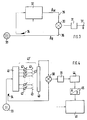
- 3 shows the basic structure of a homodyne measuring system.
- 30 denotes a mixer, to which signals are fed via lines 35 and 36.
- the output of the mixer 30 is fed to a low-pass filter 31, at the output 37 of which the desired signal is present.
- 32 designates a transmission element whose complex transfer function is to be determined using the arrangement shown.
- 33 designates a high-frequency generator, the output signal of which is fed to mixer 30 via line 36. At the same time, the output signal of the generator 33 is coupled into the transmission element 32 via a coupler 34.
- the aim of the entire arrangement is to obtain the real part of the complex transfer function of the transfer element 32 at the output 37. Assuming that the amount of the signal at input 35 is significantly smaller than the amount of the signal at input 36, that is, the mixer 30 works in linear mode, the following results:
- a signal A M reaches the mixer 30 via the line 35.
- the real part of the complex transfer function of the transfer element 32 is available at the output 37.
- FIG. 4 shows an antenna of a microwave landing system (MLS system) in which the homodyne measuring method according to FIG. 3 is used to obtain the aperture assignment of the antenna.
- the same reference numerals designate the same elements as in the other figures.
- the elements mixer 30, low-pass 31, high-frequency signal source 33 and coupling element 34, which are already known from FIG. 3, are designated.
- a monitor is designated by 40, for example designed as an integral monitor waveguide, as number 10 in FIG. 1.
- a network is designated by 41, which distributes the electrical energy originating from the radio-frequency source 33 via phase shifters designated by 42 to antenna elements of the array antenna designated by 43. With 43 'the entirety of the emitter and the phase shifter is designated.
- Signals are coupled from the antenna elements into the integral monitor waveguide 40.
- the output signal of the integral monitor waveguide is fed to the mixer 30, into which the high-frequency signal coupled in with the aid of the coupler 34 also arrives.
- the voltage U described in connection with FIG. 3 is available behind the low-pass filter 31. This voltage U is the real part of the output signal of the integral monitor waveguide 40.
- the voltage U present at the output of the low pass 31 is digitized by means of a sample-and-hold element 44 and an analog / digital converter 45. A time- and value-discrete signal is thus available at the output of the analog / digital converter 45.
- This discrete-time and value-discrete signal is converted with the aid of a signal processor 46 by means of the discrete Hilbert transformation to the still missing imaginary part of the output signal of the integral monitor waveguide 40 calculated. After this operation, the complete complex far field signal of the phased array antenna is available. Use of the discrete Fourier transform (DFT) or the fast Fourier transform (FFT) then provides the back transformation for the aperture assignment of the antenna.
- DFT discrete Fourier transform
- FFT fast Fourier transform
- FIG. 5 now shows in more detail how the phase-controlled group antenna according to FIG. 4 is calibrated.
- the same reference numerals designate the same elements as in FIG. 4.
- the phase-controlled group antenna with its radiators 43 is provided here as a block with the reference numeral 43.
- the phase shifters also appear as a block with the reference numeral 42.
- 50 denotes a signal present at the output of the integral waveguide 40 which corresponds to the far field of the antenna.
- This signal 50 corresponding to the far field of the antenna is subjected to an integral transformation in a computing unit denoted by 46 'in order to obtain the aperture assignment of the antenna.
- a control device is designated, the Output signal of the computing device 46 'is supplied.
- the nominal value for the phase adjustment of the phase shifter, designated 42, is entered via a line labeled 52, a sum point, designated 53.
- the output signal of the control device 51 is subtracted from this nominal value via a line labeled 54.
- the difference signal between the setpoint on line 52 and the output signal of the control device 51 reaches the phase shifter via line 54.
- the computing device 46 ′ which is designated separately in FIG. 4, the control device 51, the summation point 53 and the line with the setpoints 52 can each be implemented as a program after execution in a signal processor. All of the steps required to carry out the method can be carried out, for example, in the signal processor 46 in FIG. 4. It is clear from FIG. 5 that a control circuit according to FIG.
- the aperture assignment is obtained by Hilbert transformation of the output signal of an integral monitor waveguide.
Landscapes
- Variable-Direction Aerials And Aerial Arrays (AREA)
- Radar Systems Or Details Thereof (AREA)
- Details Of Aerials (AREA)
- Burglar Alarm Systems (AREA)
Applications Claiming Priority (4)
| Application Number | Priority Date | Filing Date | Title |
|---|---|---|---|
| DE4012101 | 1990-04-14 | ||
| DE19904012101 DE4012101A1 (de) | 1990-04-14 | 1990-04-14 | Verfahren und vorrichtung zur gewinnung der aperturbelegung von phasengesteuerten gruppenantennen |
| DE19904014320 DE4014320A1 (de) | 1990-05-04 | 1990-05-04 | Verfahren und vorrichtung zur automatischen kalibrierung einer phasengesteuerten gruppenantenne |
| DE4014320 | 1990-05-04 |
Publications (2)
| Publication Number | Publication Date |
|---|---|
| EP0452799A1 EP0452799A1 (de) | 1991-10-23 |
| EP0452799B1 true EP0452799B1 (de) | 1994-10-19 |
Family
ID=25892241
Family Applications (1)
| Application Number | Title | Priority Date | Filing Date |
|---|---|---|---|
| EP91105723A Expired - Lifetime EP0452799B1 (de) | 1990-04-14 | 1991-04-11 | Verfahren und Vorrichtung zur automatischen Kalibrierung einer phasengesteuerten Gruppenantenne |
Country Status (10)
| Country | Link |
|---|---|
| US (1) | US5187486A (no) |
| EP (1) | EP0452799B1 (no) |
| JP (1) | JPH05333075A (no) |
| CN (1) | CN1020831C (no) |
| AU (1) | AU641742B2 (no) |
| CA (1) | CA2040292C (no) |
| CS (1) | CS101991A2 (no) |
| DE (1) | DE59103257D1 (no) |
| NO (1) | NO177475C (no) |
| RU (1) | RU2037161C1 (no) |
Cited By (1)
| Publication number | Priority date | Publication date | Assignee | Title |
|---|---|---|---|---|
| RU2495449C2 (ru) * | 2011-11-15 | 2013-10-10 | Федеральное государственное унитарное предприятие "Ростовский-на-Дону научно-исследовательский институт радиосвязи" (ФГУП "РНИИРС") | Устройство формирования диаграммы направленности активной фазированной антенной решетки |
Families Citing this family (26)
| Publication number | Priority date | Publication date | Assignee | Title |
|---|---|---|---|---|
| DE4227857A1 (de) * | 1992-08-22 | 1994-02-24 | Sel Alcatel Ag | Einrichtung zur Gewinnung der Aperturbelegung einer phasengesteuerten Gruppenantenne |
| US5254998A (en) * | 1992-11-02 | 1993-10-19 | Allied-Signal Inc. | Executive monitor for microwave landing system |
| US6113702A (en) | 1995-09-01 | 2000-09-05 | Asm America, Inc. | Wafer support system |
| DE19711655A1 (de) * | 1997-03-20 | 1998-09-24 | Alsthom Cge Alcatel | Integralmonitornetzwerk, Antennenanlage und Sendeanlage für ein Instrumentenlandesystem (ILS) |
| US6046697A (en) * | 1997-09-05 | 2000-04-04 | Northern Telecom Limited | Phase control of transmission antennas |
| US6982670B2 (en) * | 2003-06-04 | 2006-01-03 | Farrokh Mohamadi | Phase management for beam-forming applications |
| US7042388B2 (en) * | 2003-07-15 | 2006-05-09 | Farrokh Mohamadi | Beacon-on-demand radar transponder |
| US7439905B2 (en) * | 2004-09-13 | 2008-10-21 | Fujitsu Ten Limited | Radar apparatus |
| EP1804334A1 (en) * | 2005-12-27 | 2007-07-04 | Nederlandse Organisatie voor Toegepast-Natuuurwetenschappelijk Onderzoek TNO | Phased array antenna apparatus |
| EP2372837B1 (en) | 2010-03-18 | 2016-01-06 | Alcatel Lucent | Calibration of active antenna arrays for mobile telecommunications |
| CN101964449A (zh) * | 2010-08-27 | 2011-02-02 | 中国科学院上海微系统与信息技术研究所 | 一种星载相控阵发射天线的在轨校正装置 |
| JP5104938B2 (ja) * | 2010-12-09 | 2012-12-19 | 株式会社デンソー | フェーズドアレイアンテナの位相校正方法及びフェーズドアレイアンテナ |
| JP5246250B2 (ja) * | 2010-12-09 | 2013-07-24 | 株式会社デンソー | フェーズドアレイアンテナの位相校正方法及びフェーズドアレイアンテナ |
| US8686896B2 (en) * | 2011-02-11 | 2014-04-01 | Src, Inc. | Bench-top measurement method, apparatus and system for phased array radar apparatus calibration |
| RU2467346C1 (ru) * | 2011-07-04 | 2012-11-20 | Федеральное государственное унитарное предприятие "Ростовский-на-Дону научно-исследовательский институт радиосвязи" (ФГУП "РНИИРС") | Способ калибровки активной фазированной антенной решетки |
| US9019153B1 (en) * | 2011-12-20 | 2015-04-28 | Raytheon Company | Calibration of large phased arrays using fourier gauge |
| WO2013123496A1 (en) * | 2012-02-16 | 2013-08-22 | Src, Inc. | System and method for antenna pattern estimation |
| US9209523B2 (en) | 2012-02-24 | 2015-12-08 | Futurewei Technologies, Inc. | Apparatus and method for modular multi-sector active antenna system |
| US9130271B2 (en) * | 2012-02-24 | 2015-09-08 | Futurewei Technologies, Inc. | Apparatus and method for an active antenna system with near-field radio frequency probes |
| DE102012204174B4 (de) * | 2012-03-16 | 2022-03-10 | Rohde & Schwarz GmbH & Co. Kommanditgesellschaft | Verfahren, System und Kalibrierobjekt zur automatischen Kalibrierung einer bildgebenden Antennenanordnung |
| US10720702B2 (en) * | 2016-01-08 | 2020-07-21 | National Chung Shan Institute Of Science And Technology | Method and device for correcting antenna phase |
| RU2641615C2 (ru) * | 2016-05-04 | 2018-01-18 | Федеральное государственное бюджетное военное образовательное учреждение высшего образования "Военно-космическая академия имени А.Ф. Можайского" Министерства обороны Российской Федерации | Способ и устройство для калибровки приемной активной фазированной антенной решетки |
| CN106443211B (zh) * | 2016-07-29 | 2019-03-26 | 西安空间无线电技术研究所 | 一种适用于不同有源阵列天线的一体化校正系统及校正方法 |
| RU2655655C1 (ru) * | 2017-07-13 | 2018-05-30 | Федеральное государственное унитарное предприятие "Ростовский-на-Дону научно-исследовательский институт радиосвязи" (ФГУП "РНИИРС") | Способ коррекции амплитудно-фазового распределения раскрываемой антенной решетки космического аппарата на орбите |
| DE102018112092A1 (de) * | 2018-01-10 | 2019-07-11 | Infineon Technologies Ag | Integrierte mehrkanal-hf-schaltung mit phasenerfassung |
| US11722211B1 (en) | 2020-02-13 | 2023-08-08 | Ast & Science, Llc | AOCS system to maintain planarity for space digital beam forming using carrier phase differential GPS, IMU and magnet torques on large space structures |
Family Cites Families (5)
| Publication number | Priority date | Publication date | Assignee | Title |
|---|---|---|---|---|
| US488155A (en) * | 1892-12-13 | Elevated railway | ||
| US4453164A (en) * | 1982-07-26 | 1984-06-05 | Rca Corporation | Method of determining excitation of individual elements of a phase array antenna from near-field data |
| US4488155A (en) * | 1982-07-30 | 1984-12-11 | The United States Of America As Represented By The Administrator Of The National Aeronautics And Space Administration | Method and apparatus for self-calibration and phasing of array antenna |
| US4520361A (en) * | 1983-05-23 | 1985-05-28 | Hazeltine Corporation | Calibration of a system having plural signal-carrying channels |
| US4926186A (en) * | 1989-03-20 | 1990-05-15 | Allied-Signal Inc. | FFT-based aperture monitor for scanning phased arrays |
-
1991
- 1991-03-27 NO NO911250A patent/NO177475C/no not_active IP Right Cessation
- 1991-04-10 CS CS911019A patent/CS101991A2/cs unknown
- 1991-04-10 AU AU74234/91A patent/AU641742B2/en not_active Expired
- 1991-04-11 DE DE59103257T patent/DE59103257D1/de not_active Expired - Lifetime
- 1991-04-11 EP EP91105723A patent/EP0452799B1/de not_active Expired - Lifetime
- 1991-04-11 CA CA002040292A patent/CA2040292C/en not_active Expired - Lifetime
- 1991-04-12 US US07/684,674 patent/US5187486A/en not_active Expired - Lifetime
- 1991-04-13 RU SU914895145A patent/RU2037161C1/ru active
- 1991-04-13 CN CN91102393A patent/CN1020831C/zh not_active Expired - Fee Related
- 1991-04-15 JP JP3109849A patent/JPH05333075A/ja active Pending
Cited By (1)
| Publication number | Priority date | Publication date | Assignee | Title |
|---|---|---|---|---|
| RU2495449C2 (ru) * | 2011-11-15 | 2013-10-10 | Федеральное государственное унитарное предприятие "Ростовский-на-Дону научно-исследовательский институт радиосвязи" (ФГУП "РНИИРС") | Устройство формирования диаграммы направленности активной фазированной антенной решетки |
Also Published As
| Publication number | Publication date |
|---|---|
| CA2040292C (en) | 1995-12-05 |
| CS101991A2 (en) | 1991-12-17 |
| NO911250D0 (no) | 1991-03-27 |
| NO177475B (no) | 1995-06-12 |
| RU2037161C1 (ru) | 1995-06-09 |
| NO911250L (no) | 1991-10-15 |
| AU7423491A (en) | 1991-10-17 |
| JPH05333075A (ja) | 1993-12-17 |
| AU641742B2 (en) | 1993-09-30 |
| EP0452799A1 (de) | 1991-10-23 |
| US5187486A (en) | 1993-02-16 |
| CN1020831C (zh) | 1993-05-19 |
| DE59103257D1 (de) | 1994-11-24 |
| CA2040292A1 (en) | 1991-10-15 |
| CN1055836A (zh) | 1991-10-30 |
| NO177475C (no) | 1995-09-20 |
Similar Documents
| Publication | Publication Date | Title |
|---|---|---|
| EP0452799B1 (de) | Verfahren und Vorrichtung zur automatischen Kalibrierung einer phasengesteuerten Gruppenantenne | |
| DE69627777T2 (de) | Pulsbasiertes Impedanz-Messgerät | |
| DE3917003C2 (no) | ||
| DE3535463C2 (de) | Antennensystem für die NMR-Bilddarstellung oder NMR-Spektroskopie sowie Verfahren zum Betrieb eines solchen Antennensystems | |
| DE10165055B4 (de) | Korrelationsfunktions-Messverfahren und -Vorrichtung | |
| DE102012006195A1 (de) | Vektorieller Netzwerkanalysator | |
| DE2110175A1 (de) | Verfahren und Vorrichtung zur automatischen Phasenkontrolle bei einer Fourier-Analyse von abgelesenen Impulsresonanzdaten | |
| DE102020115709B3 (de) | Automobilradaranordnung und verfahren zur objektdetektion durch ein fahrzeugradar | |
| DE102013226170A1 (de) | Verfahren und Vorrichtung zur räumlichen Homogenisierung der Feldstärke von Hochfrequenzpulsen einer Sendeantenne eines Magnetresonanztomographiegerätes | |
| DE3112112C1 (de) | Pruefvorrichtung fuer ein Radargeraet mit synthetischer Apertur | |
| DE102020008040A1 (de) | Radarempfangssystem und verfahren zur kompensation eines phasenfehlers zwischen radarempfangsschaltungen | |
| DE19750349C2 (de) | Netzwerk-Analysator | |
| DE1909205A1 (de) | Zylinderfoermiges Antennensystem mit elektronischer Rotation des Strahlungsdiagrammes | |
| EP1913408B1 (de) | Messvorrichtung, insbesondere vektorieller netzwerkanalysator, mit phasenregelung | |
| DE3301625C1 (de) | Verfahren und Vorrichtung zum Vermindern der Leistung von Störsignalen, die aus den Nebenkeulen der Antenne eines frequenzagilen Radargeräts empfangen werden | |
| DE4012101A1 (de) | Verfahren und vorrichtung zur gewinnung der aperturbelegung von phasengesteuerten gruppenantennen | |
| DE4207045C2 (de) | Digitales Frequenzerzeugungsgerät | |
| DE102019128204B4 (de) | Verfahren zum Kalibrieren eines Mikrowellenmoduls, Kalibriersystem, Mikrowellenmodul sowie Gargerät | |
| DE2505697C1 (de) | Stroerschutzverfahren fuer eine Antenne mit elektronischer Strahlschwenkung und Antenne zur Anwendung des Verfahrens | |
| EP1846774A1 (de) | Verfahren und anordnung zur korrektur der r]ckwirkung elektrischer messwandler auf das messobjekt | |
| EP1267442B1 (de) | Verfahren zur Rekonstruktion der Amplituden/Phasendiagramme der Sende-Empfangs-Module einer phasengesteuerten Gruppenantenne | |
| DE102010046903B4 (de) | Messsystem und Messverfahren zur EMV-Messung | |
| DE4404046C2 (de) | Verfahren zum Kalibrieren eines zwei Meßtore aufweisenden Netzwerk-Analysators | |
| DE4014320A1 (de) | Verfahren und vorrichtung zur automatischen kalibrierung einer phasengesteuerten gruppenantenne | |
| DE2852802C2 (no) |
Legal Events
| Date | Code | Title | Description |
|---|---|---|---|
| PUAI | Public reference made under article 153(3) epc to a published international application that has entered the european phase |
Free format text: ORIGINAL CODE: 0009012 |
|
| AK | Designated contracting states |
Kind code of ref document: A1 Designated state(s): DE FR GB IT |
|
| 17P | Request for examination filed |
Effective date: 19911118 |
|
| RAP3 | Party data changed (applicant data changed or rights of an application transferred) |
Owner name: ALCATEL SEL AKTIENGESELLSCHAFT |
|
| 17Q | First examination report despatched |
Effective date: 19940309 |
|
| GRAA | (expected) grant |
Free format text: ORIGINAL CODE: 0009210 |
|
| AK | Designated contracting states |
Kind code of ref document: B1 Designated state(s): DE FR GB IT |
|
| REF | Corresponds to: |
Ref document number: 59103257 Country of ref document: DE Date of ref document: 19941124 |
|
| GBT | Gb: translation of ep patent filed (gb section 77(6)(a)/1977) |
Effective date: 19941103 |
|
| ITF | It: translation for a ep patent filed |
Owner name: DOTT. ANTONIO SERGI |
|
| ET | Fr: translation filed | ||
| PLBE | No opposition filed within time limit |
Free format text: ORIGINAL CODE: 0009261 |
|
| STAA | Information on the status of an ep patent application or granted ep patent |
Free format text: STATUS: NO OPPOSITION FILED WITHIN TIME LIMIT |
|
| 26N | No opposition filed | ||
| REG | Reference to a national code |
Ref country code: GB Ref legal event code: IF02 |
|
| PGFP | Annual fee paid to national office [announced via postgrant information from national office to epo] |
Ref country code: GB Payment date: 20100325 Year of fee payment: 20 |
|
| PGFP | Annual fee paid to national office [announced via postgrant information from national office to epo] |
Ref country code: FR Payment date: 20100521 Year of fee payment: 20 |
|
| PGFP | Annual fee paid to national office [announced via postgrant information from national office to epo] |
Ref country code: DE Payment date: 20100430 Year of fee payment: 20 Ref country code: IT Payment date: 20100420 Year of fee payment: 20 |
|
| REG | Reference to a national code |
Ref country code: DE Ref legal event code: R071 Ref document number: 59103257 Country of ref document: DE |
|
| REG | Reference to a national code |
Ref country code: GB Ref legal event code: PE20 Expiry date: 20110410 |
|
| PG25 | Lapsed in a contracting state [announced via postgrant information from national office to epo] |
Ref country code: GB Free format text: LAPSE BECAUSE OF EXPIRATION OF PROTECTION Effective date: 20110410 |
|
| PG25 | Lapsed in a contracting state [announced via postgrant information from national office to epo] |
Ref country code: DE Free format text: LAPSE BECAUSE OF EXPIRATION OF PROTECTION Effective date: 20110411 |