EP0452645A1 - Dispositif d'électrode d'allumage à chauffage électrique - Google Patents
Dispositif d'électrode d'allumage à chauffage électrique Download PDFInfo
- Publication number
- EP0452645A1 EP0452645A1 EP91103036A EP91103036A EP0452645A1 EP 0452645 A1 EP0452645 A1 EP 0452645A1 EP 91103036 A EP91103036 A EP 91103036A EP 91103036 A EP91103036 A EP 91103036A EP 0452645 A1 EP0452645 A1 EP 0452645A1
- Authority
- EP
- European Patent Office
- Prior art keywords
- insulator
- sleeve
- electrode device
- ignition electrode
- heating winding
- Prior art date
- Legal status (The legal status is an assumption and is not a legal conclusion. Google has not performed a legal analysis and makes no representation as to the accuracy of the status listed.)
- Withdrawn
Links
Images

Classifications
-
- H—ELECTRICITY
- H01—ELECTRIC ELEMENTS
- H01T—SPARK GAPS; OVERVOLTAGE ARRESTERS USING SPARK GAPS; SPARKING PLUGS; CORONA DEVICES; GENERATING IONS TO BE INTRODUCED INTO NON-ENCLOSED GASES
- H01T13/00—Sparking plugs
- H01T13/02—Details
- H01T13/18—Means for heating, e.g. for drying
Definitions
- the invention relates to an electrically heatable ignition electrode device according to the preamble of patent claim 1.
- An ignition electrode device - as a spark plug - this type is known from DE-OS 20 45 805.
- the insulator is wrapped in a track defined by a helical recess with a heating wire, over which an insulating ceramic sleeve is pushed.
- the heating winding and the ceramic sleeve surround only a part of the insulator that is remote from the center electrode, while the tip of the insulator in the combustion chamber is free. In this way, that part of the insulator surface on which the combustion residues - generally soot or a soot-fuel mixture - are deposited is only insufficiently and, above all, slowly heated.
- a similarly constructed heated spark plug is known from DE-OS 22 35 370.
- the part of the insulator which is remote from the tip is wound with a heating winding in predetermined helical recesses, the distance between the individual turns also being a multiple of the wire thickness.
- the heating winding is surrounded on the outside by a ceramic mass applied by flame spraying.
- the object of the invention is to design an electrically heated ignition electrode device of the type mentioned in such a way that the part of the insulator structure which is primarily loaded with combustion residues is heated more rapidly to temperatures which are closer to the temperature reached in the area of the coil winding.
- the central electrode end of the ceramic sleeve becomes hotter than the insulator tip in the known heatable spark plugs for the same heating power.
- the temperature of 600 ° C. and more necessary for burning off the combustion residues can be reached even with a lower heating output.
- this temperature is reached faster than is the case in the prior art, where the heating-up time can be 10 minutes and more.
- the heat transfer to the tip area of the insulator structure is further improved in that an intermediate space between the combustion chamber end of the sleeve and the insulator is filled with a glaze or kit layer.
- the heating winding is formed by a prepared part with adjoining turns of oxide-layer insulated wire which can be pushed onto the insulator.
- the specific heating power is maximized, on the one hand, and on the other hand, the heating winding can be prefabricated so that it can be pushed onto the insulator.
- the heating winding extends to the middle electrode end of the insulator and the middle electrode end of the sleeve is drawn around the insulator to the center electrode. This further improves the heating of the surface that is loaded with deposits.
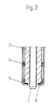
- an insulator 2 is arranged in a housing body 1 made of metal, in which in turn a center electrode 5 is arranged, which protrudes with its tip from the insulator 2.
- a heating winding 4 with closely adjacent turns made of oxide-layer insulated high-temperature resistant resistance wire is arranged, which is covered with a ceramic filling compound 9, for example made of baking soda or
- Potash water glass and Al2O3 is embedded in a cylindrical ceramic sleeve 7 surrounding the heating winding, which extends from the housing body 1 over the entire protruding part of the insulator 2 to its center-electrode tip.
- the heating winding 4 surrounds only part of the part of the insulator 2 protruding from the housing body 1 and leaves a space between the sleeve 7 and the insulator 2 on the tip side. This space is filled with an electrically insulating glaze or kit layer 6 in the region of the conically tapering end of the insulator.
- the ceramic filling compound 9 extends behind it.
- the heating winding 4 made of oxide-layer insulated high-temperature resistant resistance wire is prefabricated and is pushed as a whole onto the insulator. With this joining technique it is no longer necessary to use the insulator as a winding mandrel.
- the end of the resistance wire on the middle electrode side which does not need to be wound bifilarly, is returned within the heating winding through a ceramic tube 8 to a connector plug 3 which is located in the region of the end of the ignition electrode device remote from the center electrode.
- the other resistance wire end of the heating winding 4 is welded to the housing body 1 made of metal.
- the sleeve 7 made of ceramic has a smooth surface, which favors a good jumping off of the deposit layer, which mostly consists of soot or a soot-fuel mixture or soot-fuel mixture.
- the heating winding 4 extends into the area of the tip of the insulator 2.
- the sleeve 7 made of ceramic at the end of the insulator 2 is drawn around the latter to the center electrode 5 and connected there by means of the glaze or kit layer 6.
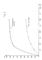
- Fig. 3 shows the temperature on the sleeve 7 in the area of the heating winding as a function of time for the embodiment according to FIG. 1 in comparison to a known structure which corresponds approximately to the spark plug of DE-OS 22 35 370.
- the temperature of the latter was also measured in the area of the heating coil.
- the heating power was about 60 watts in both cases.
Landscapes
- Spark Plugs (AREA)
Applications Claiming Priority (2)
| Application Number | Priority Date | Filing Date | Title |
|---|---|---|---|
| DE19904007190 DE4007190C1 (fr) | 1990-03-07 | 1990-03-07 | |
| DE4007190 | 1990-03-07 |
Publications (1)
| Publication Number | Publication Date |
|---|---|
| EP0452645A1 true EP0452645A1 (fr) | 1991-10-23 |
Family
ID=6401628
Family Applications (1)
| Application Number | Title | Priority Date | Filing Date |
|---|---|---|---|
| EP91103036A Withdrawn EP0452645A1 (fr) | 1990-03-07 | 1991-02-28 | Dispositif d'électrode d'allumage à chauffage électrique |
Country Status (2)
| Country | Link |
|---|---|
| EP (1) | EP0452645A1 (fr) |
| DE (1) | DE4007190C1 (fr) |
Cited By (2)
| Publication number | Priority date | Publication date | Assignee | Title |
|---|---|---|---|---|
| EP0630086A1 (fr) * | 1993-06-16 | 1994-12-21 | NGK Spark Plug Co. Ltd. | Bougie d'allumage munie d'un élément chauffant |
| WO2010148457A1 (fr) * | 2009-06-26 | 2010-12-29 | Orbital Australia Pty Limited | Combustion de carburants à faible pression de vapeur dans des moteurs à allumage par étincelle |
Citations (1)
| Publication number | Priority date | Publication date | Assignee | Title |
|---|---|---|---|---|
| GB2185529A (en) * | 1986-01-16 | 1987-07-22 | Nigel John Wilkinson | Sparkplug |
Family Cites Families (3)
| Publication number | Priority date | Publication date | Assignee | Title |
|---|---|---|---|---|
| DE2045805A1 (de) * | 1970-09-16 | 1972-03-23 | Eyquem | Zündkerze fur einen Verbrennungs motor |
| DE7130903U (de) * | 1971-08-12 | 1972-04-27 | Beru-Werk A Ruprecht | Zuendkerze mit eletrisch beheiztem isolatorfuss |
| DE2235370A1 (de) * | 1972-07-19 | 1974-01-31 | Daimler Benz Ag | Elektrisch beheizte zuendkerze fuer brennkraftmaschinen |
-
1990
- 1990-03-07 DE DE19904007190 patent/DE4007190C1/de not_active Expired - Lifetime
-
1991
- 1991-02-28 EP EP91103036A patent/EP0452645A1/fr not_active Withdrawn
Patent Citations (1)
| Publication number | Priority date | Publication date | Assignee | Title |
|---|---|---|---|---|
| GB2185529A (en) * | 1986-01-16 | 1987-07-22 | Nigel John Wilkinson | Sparkplug |
Cited By (2)
| Publication number | Priority date | Publication date | Assignee | Title |
|---|---|---|---|---|
| EP0630086A1 (fr) * | 1993-06-16 | 1994-12-21 | NGK Spark Plug Co. Ltd. | Bougie d'allumage munie d'un élément chauffant |
| WO2010148457A1 (fr) * | 2009-06-26 | 2010-12-29 | Orbital Australia Pty Limited | Combustion de carburants à faible pression de vapeur dans des moteurs à allumage par étincelle |
Also Published As
| Publication number | Publication date |
|---|---|
| DE4007190C1 (fr) | 1991-09-26 |
Similar Documents
| Publication | Publication Date | Title |
|---|---|---|
| DE3340359C2 (fr) | ||
| DE3607888C2 (fr) | ||
| DE2900984A1 (de) | Gluehkerze fuer dieselmotoren | |
| DE4028860C2 (de) | Glühkerze mit eigener Temperatursteuerung | |
| DE3802233C2 (fr) | ||
| DE19630402C2 (de) | Stabflammglühkerze | |
| DE1526775A1 (de) | Starthilfe fuer Brennkraftmaschinen | |
| DE4007190C1 (fr) | ||
| EP0413147B1 (fr) | Bougie-crayon à incandescence | |
| DE4303581A1 (de) | Elektrisch isolierende gasdichte Durchführung mindestens eines elektrischen Leiters durch einen metallischen Mantel | |
| DE2739413A1 (de) | Zuendkerze | |
| DE3003799C2 (de) | Glühkerze für Brennkraftmaschinen | |
| DE19732426A1 (de) | Temperaturbegrenzer mit Zündelement | |
| DE3035542A1 (de) | Gluehstiftkerze fuer brennkraftmaschinen | |
| EP0392181B1 (fr) | Bougie à incandescence | |
| DD147391A5 (de) | Elektrische gluehkerze fuer verbrennungsmotoren | |
| DE112011101617T5 (de) | Zündkerze | |
| DE3309133A1 (de) | Flammgluehstiftkerze zum vorwaermen der ansaugluft von brennkraftmaschinen | |
| DE2637435A1 (de) | Gluehstiftkerze fuer brennkraftmaschinen | |
| DE3006747C2 (fr) | ||
| DE2634798C3 (de) | Glühzündkerze | |
| DE3726714C2 (fr) | ||
| DE1280459B (de) | Gluehzuender fuer Heizoelverdampfungsbrenner | |
| DE1526775C (de) | Starthilfe fur Brennkraftmaschinen | |
| EP0337216B1 (fr) | Bougie à incandescence pour chambre de combustion d'un moteur à compression d'air |
Legal Events
| Date | Code | Title | Description |
|---|---|---|---|
| PUAI | Public reference made under article 153(3) epc to a published international application that has entered the european phase |
Free format text: ORIGINAL CODE: 0009012 |
|
| AK | Designated contracting states |
Kind code of ref document: A1 Designated state(s): AT ES FR GB IT NL SE |
|
| 17P | Request for examination filed |
Effective date: 19920410 |
|
| STAA | Information on the status of an ep patent application or granted ep patent |
Free format text: STATUS: THE APPLICATION IS DEEMED TO BE WITHDRAWN |
|
| 18D | Application deemed to be withdrawn |
Effective date: 19940830 |