EP0452645A1 - Electrically heatable ignition electrode device - Google Patents
Electrically heatable ignition electrode device Download PDFInfo
- Publication number
- EP0452645A1 EP0452645A1 EP91103036A EP91103036A EP0452645A1 EP 0452645 A1 EP0452645 A1 EP 0452645A1 EP 91103036 A EP91103036 A EP 91103036A EP 91103036 A EP91103036 A EP 91103036A EP 0452645 A1 EP0452645 A1 EP 0452645A1
- Authority
- EP
- European Patent Office
- Prior art keywords
- insulator
- sleeve
- electrode device
- ignition electrode
- heating winding
- Prior art date
- Legal status (The legal status is an assumption and is not a legal conclusion. Google has not performed a legal analysis and makes no representation as to the accuracy of the status listed.)
- Withdrawn
Links
Images

Classifications
-
- H—ELECTRICITY
- H01—ELECTRIC ELEMENTS
- H01T—SPARK GAPS; OVERVOLTAGE ARRESTERS USING SPARK GAPS; SPARKING PLUGS; CORONA DEVICES; GENERATING IONS TO BE INTRODUCED INTO NON-ENCLOSED GASES
- H01T13/00—Sparking plugs
- H01T13/02—Details
- H01T13/18—Means for heating, e.g. for drying
Definitions
- the invention relates to an electrically heatable ignition electrode device according to the preamble of patent claim 1.
- An ignition electrode device - as a spark plug - this type is known from DE-OS 20 45 805.
- the insulator is wrapped in a track defined by a helical recess with a heating wire, over which an insulating ceramic sleeve is pushed.
- the heating winding and the ceramic sleeve surround only a part of the insulator that is remote from the center electrode, while the tip of the insulator in the combustion chamber is free. In this way, that part of the insulator surface on which the combustion residues - generally soot or a soot-fuel mixture - are deposited is only insufficiently and, above all, slowly heated.
- a similarly constructed heated spark plug is known from DE-OS 22 35 370.
- the part of the insulator which is remote from the tip is wound with a heating winding in predetermined helical recesses, the distance between the individual turns also being a multiple of the wire thickness.
- the heating winding is surrounded on the outside by a ceramic mass applied by flame spraying.
- the object of the invention is to design an electrically heated ignition electrode device of the type mentioned in such a way that the part of the insulator structure which is primarily loaded with combustion residues is heated more rapidly to temperatures which are closer to the temperature reached in the area of the coil winding.
- the central electrode end of the ceramic sleeve becomes hotter than the insulator tip in the known heatable spark plugs for the same heating power.
- the temperature of 600 ° C. and more necessary for burning off the combustion residues can be reached even with a lower heating output.
- this temperature is reached faster than is the case in the prior art, where the heating-up time can be 10 minutes and more.
- the heat transfer to the tip area of the insulator structure is further improved in that an intermediate space between the combustion chamber end of the sleeve and the insulator is filled with a glaze or kit layer.
- the heating winding is formed by a prepared part with adjoining turns of oxide-layer insulated wire which can be pushed onto the insulator.
- the specific heating power is maximized, on the one hand, and on the other hand, the heating winding can be prefabricated so that it can be pushed onto the insulator.
- the heating winding extends to the middle electrode end of the insulator and the middle electrode end of the sleeve is drawn around the insulator to the center electrode. This further improves the heating of the surface that is loaded with deposits.
- an insulator 2 is arranged in a housing body 1 made of metal, in which in turn a center electrode 5 is arranged, which protrudes with its tip from the insulator 2.
- a heating winding 4 with closely adjacent turns made of oxide-layer insulated high-temperature resistant resistance wire is arranged, which is covered with a ceramic filling compound 9, for example made of baking soda or
- Potash water glass and Al2O3 is embedded in a cylindrical ceramic sleeve 7 surrounding the heating winding, which extends from the housing body 1 over the entire protruding part of the insulator 2 to its center-electrode tip.
- the heating winding 4 surrounds only part of the part of the insulator 2 protruding from the housing body 1 and leaves a space between the sleeve 7 and the insulator 2 on the tip side. This space is filled with an electrically insulating glaze or kit layer 6 in the region of the conically tapering end of the insulator.
- the ceramic filling compound 9 extends behind it.
- the heating winding 4 made of oxide-layer insulated high-temperature resistant resistance wire is prefabricated and is pushed as a whole onto the insulator. With this joining technique it is no longer necessary to use the insulator as a winding mandrel.
- the end of the resistance wire on the middle electrode side which does not need to be wound bifilarly, is returned within the heating winding through a ceramic tube 8 to a connector plug 3 which is located in the region of the end of the ignition electrode device remote from the center electrode.
- the other resistance wire end of the heating winding 4 is welded to the housing body 1 made of metal.
- the sleeve 7 made of ceramic has a smooth surface, which favors a good jumping off of the deposit layer, which mostly consists of soot or a soot-fuel mixture or soot-fuel mixture.
- the heating winding 4 extends into the area of the tip of the insulator 2.
- the sleeve 7 made of ceramic at the end of the insulator 2 is drawn around the latter to the center electrode 5 and connected there by means of the glaze or kit layer 6.
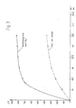
- Fig. 3 shows the temperature on the sleeve 7 in the area of the heating winding as a function of time for the embodiment according to FIG. 1 in comparison to a known structure which corresponds approximately to the spark plug of DE-OS 22 35 370.
- the temperature of the latter was also measured in the area of the heating coil.
- the heating power was about 60 watts in both cases.
Landscapes
- Spark Plugs (AREA)
Abstract
Description
Die Erfindung betrifft eine elektrisch beheizbare Zündelektrodenvorrichtung gemäß dem Oberbegriff des Patentanspruchs 1.The invention relates to an electrically heatable ignition electrode device according to the preamble of patent claim 1.
Eine Zündelektrodenvorrichtung - als Zündkerze - dieser Art ist aus der DE-OS 20 45 805 bekannt. Bei dieser bekannten Zündkerze ist der Isolator in einer durch eine wendelförmige Eintiefung vorgegebenen Spur mit einem Heizdraht umwickelt, über den seinerseits eine isolierende Keramikhülse geschoben ist. Die Heizwicklung und die Keramikhülse umgeben nur einen von der Mittelelektrode fernen Teil des Isolators, während die im Brennraum liegende Spitze des Isolators frei ist. Auf diese Weise wird gerade derjenige Teil der Isolatoroberfläche, auf dem die Verbrennungsrückstände - im allgemeinen Ruß oder ein Rußbrennstoffgemisch - zur Ablagerung gelangen, nur unzureichend und vor allem langsam erwärmt.An ignition electrode device - as a spark plug - this type is known from DE-OS 20 45 805. In this known spark plug, the insulator is wrapped in a track defined by a helical recess with a heating wire, over which an insulating ceramic sleeve is pushed. The heating winding and the ceramic sleeve surround only a part of the insulator that is remote from the center electrode, while the tip of the insulator in the combustion chamber is free. In this way, that part of the insulator surface on which the combustion residues - generally soot or a soot-fuel mixture - are deposited is only insufficiently and, above all, slowly heated.
Eine ähnlich aufgebaute beheizbare Zündkerze ist aus der DE-OS 22 35 370 bekannt. Auch bei ihr ist nur der spitzenferne Teil des Isolators in vorgegebenen wendelförmigen Eintiefungen mit einer Heizwicklung bewickelt, wobei der Abstand der einzelnen Windungen auch noch ein Mehrfaches der Drahtstärke beträgt. Nach außen umgeben ist die Heizwicklung von einer im Flammspritzverfahren aufgebrachten Keramikmasse.A similarly constructed heated spark plug is known from DE-OS 22 35 370. In this case, too, only the part of the insulator which is remote from the tip is wound with a heating winding in predetermined helical recesses, the distance between the individual turns also being a multiple of the wire thickness. The heating winding is surrounded on the outside by a ceramic mass applied by flame spraying.
Aufgabe der Erfindung ist es, eine elektrisch beheizbare Zündelektrodenvorrichtung der eingangs genannten Art so zu gestalten, daß es zu einer rascheren Erwärmung des vor allem mit Verbrennungsrückständen belasteten Teil des Isolatoraufbaus auf Temperaturen kommt, die näher bei der im Bereich der Helzwicklung erreichten Temperatur liegen.The object of the invention is to design an electrically heated ignition electrode device of the type mentioned in such a way that the part of the insulator structure which is primarily loaded with combustion residues is heated more rapidly to temperatures which are closer to the temperature reached in the area of the coil winding.
Diese Aufgabe wird erfindungsgemäß gelöst durch eine elektrisch beheizbare Zündelektrodenvorrichtung, wie sie im Patentanspruch 1 gekennzeichnet ist.This object is achieved according to the invention by an electrically heated ignition electrode device, as characterized in claim 1.
Durch die Erstreckung der Keramikhülse bis zur Isolatorspitze wird in Verbindung mit der einen guten Wärmeschluß zwischen Heizwicklung und Hülse bewirkenden keramischen Füllmasse erreicht, daß bei gleicher Heizleistung das mittelelektrodenseitige Ende der Keramikhülse heißer wird als es für die Isolatorspitze bei den bekannten beheizbaren Zündkerzen der Fall war. Dadurch läßt sich schon bei einer geringeren Heizleistung die für das Abbrennen der Verbrennungsrückstände notwendige Temperatur von 600°C und mehr erreichen. Außerdem wird diese Temperatur schneller erreicht, als es beim Stand der Technik der Fall ist, wo die Aufheizzeit 10 Minuten und mehr betragen kann.By the extension of the ceramic sleeve to the insulator tip in connection with the good thermal connection between the heating winding and the sleeve causing the ceramic filling compound, the central electrode end of the ceramic sleeve becomes hotter than the insulator tip in the known heatable spark plugs for the same heating power. As a result, the temperature of 600 ° C. and more necessary for burning off the combustion residues can be reached even with a lower heating output. In addition, this temperature is reached faster than is the case in the prior art, where the heating-up time can be 10 minutes and more.
Gemäß einer bevorzugten Ausgestaltung der Erfindung ist die Wärmeübertragung auf den Spitzenbereich des Isolatoraufbaus weiter dadurch verbessert, daß ein zwischen dem brennraumseitigen Ende der Hülse und dem Isolator vorhandener Zwischenraum mit einer Glasglasur- oder Kittschicht ausgefüllt ist.According to a preferred embodiment of the invention, the heat transfer to the tip area of the insulator structure is further improved in that an intermediate space between the combustion chamber end of the sleeve and the insulator is filled with a glaze or kit layer.
Gemäß einer weiteren bevorzugten Ausgestaltung der Erfindung ist es vorgesehen, daß die Heizwicklung durch ein vorbereitetes Teil mit aneinanderliegenden Windungen aus oxidschichtisoliertem Draht gebildet ist, welches auf den Isolator aufschiebbar ist. Durch das Aneinanderliegen der Windungen wird einerseits die spezifische Heizleistung maximalisiert, und andererseits läßt sich die Heizwicklung so vorfertigen, daß sie fertig auf den Isolator aufgeschoben werden kann. Diese Fügetechnik stellt eine entscheidende Herstellungsvereinfachung gegenüber den bekannten beheizbaren Zündkerzen dar, bei welchen der Isolator als Wickeldorn dienen mußte.According to a further preferred embodiment of the invention, it is provided that the heating winding is formed by a prepared part with adjoining turns of oxide-layer insulated wire which can be pushed onto the insulator. By the turns of the turns, the specific heating power is maximized, on the one hand, and on the other hand, the heating winding can be prefabricated so that it can be pushed onto the insulator. This joining technique represents a decisive simplification of manufacture compared to the known heatable spark plugs, in which the insulator had to serve as a winding mandrel.
Gemäß einer weiteren vorteilhaften Ausgestaltung der Erfindung ist vorgesehen, daß sich die Heizwicklung bis zum mittelelektrodenseitigen Ende des Isolators erstreckt und das mittelelektrodenseitige Ende der Hülse um den Isolator zur Mittelelektrode hin herumgezogen ist. Dadurch wird die Erwärmung der ablagerungsbelasteten Oberfläche weiter verbessert.According to a further advantageous embodiment of the invention it is provided that the heating winding extends to the middle electrode end of the insulator and the middle electrode end of the sleeve is drawn around the insulator to the center electrode. This further improves the heating of the surface that is loaded with deposits.
Ausführungsformen der Erfindung werden im folgenden anhand der beigefügten Zeichnung beschrieben. Auf dieser zeigt
- Fig. 1 im Schnitt eine erste Ausführungsform einer elektrisch beheizbaren Zündelektrodenvorrichtung gemäß der Erfindung,
- Fig. 2 im Schnitt das brennraumseitige Ende einer zweiten Ausführungsform der elektrisch beheizbaren Zündelektrodenvorrichtung gemäß der Erfindung, und
- Fig. 3 ein Diagramm, welches die erreichte Oberflächentemperatur in Abhängigkeit von der Zeit für die bekannte und die in Fig. 1 gezeigte Zündelektrodenvorrichtung wiedergibt.
- 1 shows in section a first embodiment of an electrically heatable ignition electrode device according to the invention,
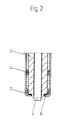
- 2 shows in section the end on the combustion chamber side of a second embodiment of the electrically heatable ignition electrode device according to the invention, and
- FIG. 3 is a diagram which shows the surface temperature reached as a function of time for the known and the ignition electrode device shown in FIG. 1.
Bei der in Fig. 1 gezeigten Zündelektrodenvorrichtung ist in einem Gehäusekörper 1 aus Metall ein Isolator 2 angeordnet, in welchem ihrerseits eine Mittelelektrode 5 angeordnet ist, die mit ihrer Spitze aus dem Isolator 2 herausragt. Auf einem die Mittelelektrode umgebenden zylindrischen Teil des Isolators 2 ist eine Heizwicklung 4 mit eng aneinanderliegenden Windungen aus oxidschichtisoliertem hochtemperaturfestem Widerstandsdraht angeordnet, die mit einer keramischen Füllmasse 9, beispielsweise aus Natron- oderIn the ignition electrode device shown in FIG. 1, an
Kaliwasserglas und Al₂O₃ in eine die Heizwicklung umgebende zylinderförmige keramische Hülse 7 eingebettet ist, die sich vom Gehäusekörper 1 über den gesamten aus diesem herausragenden Teil des Isolators 2 bis zu dessen mittelelektrodenseitiger Spitze erstreckt. Die Heizwicklung 4 umgibt nur einen Teil des aus dem Gehäusekörper 1 herausragenden Teil des Isolators 2 und läßt spitzenseitig einen Raum zwischen Hülse 7 und Isolator 2 frei. Dieser Raum ist im Bereich des konisch zulaufenden Endes des Isolators mit einer elektrisch isolierenden Glasur-oder Kittschicht 6 ausgefüllt. Dahinter erstreckt sich die keramische Füllmasse 9.Potash water glass and Al₂O₃ is embedded in a cylindrical
Die Heizwicklung 4 aus oxidschichtisoliertem hochtemperaturfestem Widerstandsdraht ist vorgefertigt und wird als ganzes auf den Isolator geschoben. Es ist durch diese Fügetechnik also nicht mehr erforderlich, den Isolator als Wickeldorn zu benutzen.The heating winding 4 made of oxide-layer insulated high-temperature resistant resistance wire is prefabricated and is pushed as a whole onto the insulator. With this joining technique it is no longer necessary to use the insulator as a winding mandrel.
Das mittelelektrodenseitige Ende des Widerstandsdrahts, der damit nicht bifilar gewickelt zu sein braucht, wird innerhalb der Heizwicklung durch ein keramisches Röhrchen 8 zu einem Anschlußstecker 3 zurückgeführt, der sich im Bereich des mittelelektrodenfernen Endes der Zündelektrodenvorrichtung befindet. Das andere Widerstandsdrahtende der Heizwicklung 4 ist mit dem Gehäusekörper 1 aus Metall verschweißt.The end of the resistance wire on the middle electrode side, which does not need to be wound bifilarly, is returned within the heating winding through a
Die Hülse 7 aus Keramik hat eine glatte Oberfläche, was ein gutes Abspringen der zumeist aus Ruß oder einem Ruß-Kraftstoffgemisch bzw. Ruß-Brennstoffgemisch bestehenden Ablagerungsschicht begünstigt.The
Bei der in Fig. 2 gezeigten Ausführungsform erstreckt sich die Heizwicklung 4 bis in den Bereich der Spitze des Isolators 2. Außerdem ist die Hülse 7 aus Keramik am Ende des Isolators 2 um diesen zur Mittelelektrode 5 hin herumgezogen und dort mit diesem mittels der Glasur- oder Kittschicht 6 verbunden. Mit dieser Ausführungsform wird eine besonders gleichmäßige und rasche Aufheizung der kritischen Oberfläche bis hin zur Mittelelektrode erreicht.In the embodiment shown in Fig. 2 extends the heating winding 4 extends into the area of the tip of the
Fig. 3 zeigt die Temperatur auf der Hülse 7 im Bereich der Heizwicklung in Abhängigkeit von der Zeit für die Ausführungsform gemäß Fig. 1 im Vergleich zu einem bekannten Aufbau, der in etwa der Zündkerze der DE-OS 22 35 370 entspricht. An letzterer wurde die Temperatur ebenfalls im Bereich der Heizwendel gemessen. Die Heizleistung betrug dabei in beiden Fällen etwa 60 Watt.Fig. 3 shows the temperature on the
Claims (5)
Applications Claiming Priority (2)
| Application Number | Priority Date | Filing Date | Title |
|---|---|---|---|
| DE4007190 | 1990-03-07 | ||
| DE19904007190 DE4007190C1 (en) | 1990-03-07 | 1990-03-07 |
Publications (1)
| Publication Number | Publication Date |
|---|---|
| EP0452645A1 true EP0452645A1 (en) | 1991-10-23 |
Family
ID=6401628
Family Applications (1)
| Application Number | Title | Priority Date | Filing Date |
|---|---|---|---|
| EP91103036A Withdrawn EP0452645A1 (en) | 1990-03-07 | 1991-02-28 | Electrically heatable ignition electrode device |
Country Status (2)
| Country | Link |
|---|---|
| EP (1) | EP0452645A1 (en) |
| DE (1) | DE4007190C1 (en) |
Cited By (2)
| Publication number | Priority date | Publication date | Assignee | Title |
|---|---|---|---|---|
| EP0630086A1 (en) * | 1993-06-16 | 1994-12-21 | NGK Spark Plug Co. Ltd. | Heater-equipped spark plug |
| WO2010148457A1 (en) * | 2009-06-26 | 2010-12-29 | Orbital Australia Pty Limited | Combustion of low vapour-pressure fuels in spark ignition engines |
Citations (1)
| Publication number | Priority date | Publication date | Assignee | Title |
|---|---|---|---|---|
| GB2185529A (en) * | 1986-01-16 | 1987-07-22 | Nigel John Wilkinson | Sparkplug |
Family Cites Families (3)
| Publication number | Priority date | Publication date | Assignee | Title |
|---|---|---|---|---|
| DE2045805A1 (en) * | 1970-09-16 | 1972-03-23 | Eyquem | Spark plug for an internal combustion engine |
| DE7130903U (en) * | 1971-08-12 | 1972-04-27 | Beru-Werk A Ruprecht | SPARK PLUG WITH ELETRICALLY HEATED INSULATOR BASE |
| DE2235370A1 (en) * | 1972-07-19 | 1974-01-31 | Daimler Benz Ag | ELECTRICALLY HEATED SPARK PLUG FOR COMBUSTION MACHINERY |
-
1990
- 1990-03-07 DE DE19904007190 patent/DE4007190C1/de not_active Expired - Lifetime
-
1991
- 1991-02-28 EP EP91103036A patent/EP0452645A1/en not_active Withdrawn
Patent Citations (1)
| Publication number | Priority date | Publication date | Assignee | Title |
|---|---|---|---|---|
| GB2185529A (en) * | 1986-01-16 | 1987-07-22 | Nigel John Wilkinson | Sparkplug |
Cited By (2)
| Publication number | Priority date | Publication date | Assignee | Title |
|---|---|---|---|---|
| EP0630086A1 (en) * | 1993-06-16 | 1994-12-21 | NGK Spark Plug Co. Ltd. | Heater-equipped spark plug |
| WO2010148457A1 (en) * | 2009-06-26 | 2010-12-29 | Orbital Australia Pty Limited | Combustion of low vapour-pressure fuels in spark ignition engines |
Also Published As
| Publication number | Publication date |
|---|---|
| DE4007190C1 (en) | 1991-09-26 |
Similar Documents
| Publication | Publication Date | Title |
|---|---|---|
| DE3340359C2 (en) | ||
| DE3607888C2 (en) | ||
| DE2900984A1 (en) | GLOW PLUG FOR DIESEL ENGINES | |
| DE3233319A1 (en) | EVAPORATION BURNER | |
| DE4028860C2 (en) | Glow plug with its own temperature control | |
| EP0821200B1 (en) | Flame glow plug | |
| DE1526775A1 (en) | Jump start for internal combustion engines | |
| DE4007190C1 (en) | ||
| DE4303581A1 (en) | Electrically insulating gas-tight passage of at least one electrical conductor through a metallic jacket | |
| EP0413147B1 (en) | Sheathed-element glow plug | |
| DE2739413A1 (en) | SPARK PLUG | |
| DE3003799C2 (en) | Glow plug for internal combustion engines | |
| DE19732426A1 (en) | Temperature limiter with ignition element | |
| DE3035542A1 (en) | Glow plug for internal combustion engines | |
| EP0392181B1 (en) | Glow plug | |
| DD147391A5 (en) | ELECTRIC GLUE CANDLE FOR INTERNAL COMBUSTION ENGINES | |
| DE112011101617T5 (en) | spark plug | |
| DE9002670U1 (en) | Electrically heated ignition electrode device | |
| DE3309133A1 (en) | FLAME GLOW PEN CANDLE FOR PREHEATING THE INTAKE AIR OF COMBUSTION ENGINES | |
| DE2637435A1 (en) | Glow plug for internal combustion engines - using resistance heater coil packed in insulating powder with good thermal conductivity | |
| DE3006747C2 (en) | ||
| DE2634798C3 (en) | Glow plug | |
| DE3726714C2 (en) | ||
| DE1280459B (en) | Incandescent light for heating oil evaporation burner | |
| DE1526775C (en) | Jump start for internal combustion engines |
Legal Events
| Date | Code | Title | Description |
|---|---|---|---|
| PUAI | Public reference made under article 153(3) epc to a published international application that has entered the european phase |
Free format text: ORIGINAL CODE: 0009012 |
|
| AK | Designated contracting states |
Kind code of ref document: A1 Designated state(s): AT ES FR GB IT NL SE |
|
| 17P | Request for examination filed |
Effective date: 19920410 |
|
| STAA | Information on the status of an ep patent application or granted ep patent |
Free format text: STATUS: THE APPLICATION IS DEEMED TO BE WITHDRAWN |
|
| 18D | Application deemed to be withdrawn |
Effective date: 19940830 |