EP0451971A1 - Festoxidbrennstoffzellen - Google Patents
Festoxidbrennstoffzellen Download PDFInfo
- Publication number
- EP0451971A1 EP0451971A1 EP91302395A EP91302395A EP0451971A1 EP 0451971 A1 EP0451971 A1 EP 0451971A1 EP 91302395 A EP91302395 A EP 91302395A EP 91302395 A EP91302395 A EP 91302395A EP 0451971 A1 EP0451971 A1 EP 0451971A1
- Authority
- EP
- European Patent Office
- Prior art keywords
- fuel cell
- air electrode
- electrode
- solid oxide
- oxide fuel
- Prior art date
- Legal status (The legal status is an assumption and is not a legal conclusion. Google has not performed a legal analysis and makes no representation as to the accuracy of the status listed.)
- Granted
Links
Images

Classifications
-
- H—ELECTRICITY
- H01—ELECTRIC ELEMENTS
- H01M—PROCESSES OR MEANS, e.g. BATTERIES, FOR THE DIRECT CONVERSION OF CHEMICAL ENERGY INTO ELECTRICAL ENERGY
- H01M8/00—Fuel cells; Manufacture thereof
- H01M8/02—Details
- H01M8/0202—Collectors; Separators, e.g. bipolar separators; Interconnectors
- H01M8/0247—Collectors; Separators, e.g. bipolar separators; Interconnectors characterised by the form
- H01M8/0252—Collectors; Separators, e.g. bipolar separators; Interconnectors characterised by the form tubular
-
- H—ELECTRICITY
- H01—ELECTRIC ELEMENTS
- H01M—PROCESSES OR MEANS, e.g. BATTERIES, FOR THE DIRECT CONVERSION OF CHEMICAL ENERGY INTO ELECTRICAL ENERGY
- H01M8/00—Fuel cells; Manufacture thereof
- H01M8/02—Details
- H01M8/0202—Collectors; Separators, e.g. bipolar separators; Interconnectors
- H01M8/0247—Collectors; Separators, e.g. bipolar separators; Interconnectors characterised by the form
-
- H—ELECTRICITY
- H01—ELECTRIC ELEMENTS
- H01M—PROCESSES OR MEANS, e.g. BATTERIES, FOR THE DIRECT CONVERSION OF CHEMICAL ENERGY INTO ELECTRICAL ENERGY
- H01M8/00—Fuel cells; Manufacture thereof
- H01M8/24—Grouping of fuel cells, e.g. stacking of fuel cells
- H01M8/241—Grouping of fuel cells, e.g. stacking of fuel cells with solid or matrix-supported electrolytes
- H01M8/2425—High-temperature cells with solid electrolytes
- H01M8/243—Grouping of unit cells of tubular or cylindrical configuration
-
- H—ELECTRICITY
- H01—ELECTRIC ELEMENTS
- H01M—PROCESSES OR MEANS, e.g. BATTERIES, FOR THE DIRECT CONVERSION OF CHEMICAL ENERGY INTO ELECTRICAL ENERGY
- H01M8/00—Fuel cells; Manufacture thereof
- H01M8/10—Fuel cells with solid electrolytes
- H01M8/12—Fuel cells with solid electrolytes operating at high temperature, e.g. with stabilised ZrO2 electrolyte
- H01M2008/1293—Fuel cells with solid oxide electrolytes
-
- H—ELECTRICITY
- H01—ELECTRIC ELEMENTS
- H01M—PROCESSES OR MEANS, e.g. BATTERIES, FOR THE DIRECT CONVERSION OF CHEMICAL ENERGY INTO ELECTRICAL ENERGY
- H01M2300/00—Electrolytes
- H01M2300/0017—Non-aqueous electrolytes
- H01M2300/0065—Solid electrolytes
- H01M2300/0068—Solid electrolytes inorganic
- H01M2300/0071—Oxides
- H01M2300/0074—Ion conductive at high temperature
-
- Y—GENERAL TAGGING OF NEW TECHNOLOGICAL DEVELOPMENTS; GENERAL TAGGING OF CROSS-SECTIONAL TECHNOLOGIES SPANNING OVER SEVERAL SECTIONS OF THE IPC; TECHNICAL SUBJECTS COVERED BY FORMER USPC CROSS-REFERENCE ART COLLECTIONS [XRACs] AND DIGESTS
- Y02—TECHNOLOGIES OR APPLICATIONS FOR MITIGATION OR ADAPTATION AGAINST CLIMATE CHANGE
- Y02E—REDUCTION OF GREENHOUSE GAS [GHG] EMISSIONS, RELATED TO ENERGY GENERATION, TRANSMISSION OR DISTRIBUTION
- Y02E60/00—Enabling technologies; Technologies with a potential or indirect contribution to GHG emissions mitigation
- Y02E60/30—Hydrogen technology
- Y02E60/50—Fuel cells
Definitions
- the present invention relates to solid oxide type fuel cells.
- fuel cells have been noted as power generating equipments.
- Such a fuel cell is an equipment capable of directly converting chemical energy possessed by fuel to electric energy. Since the fuel cell is free from limitation of Carnot's cycle, the cell is an extremely promising technique in that the fuel cell essentially has a high energy conversion efficiency, a variety of fuels (naphtha, natural gas, methanol, coal reformed gas, heavy oil, etc,) may be used, and the cell provokes less public nuisance, and its power generating efficiency is not influenced by the scale of the equipment.
- the solid oxide fuel cell hereinafter referred to as "SOFC" operates at high temperatures of 1,000°C or more, activity of electrodes is extremely high.
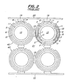
- Fig. 2 is a front view of illustrating a part of a fuel cell in which such cylindrical SOFC elements are arranged.
- an air electrode 12 is provided on the outer periphery of a cylindrical ceramic support body 11, and a solid electrolyte 5 and a fuel electrode 6 are arranged along the outer periphery of the air electrode 12. Further, an interconnector 7 is provided on the air electrode 12 in an upper zone as viewed in Fig. 2, and a connection terminal 8 is attached onto the interconnector 7. Thereby, the cylindrical SOFC element 40 is constituted.
- the air electrode 12 is connected to the fuel electrode between the upper and lower adjacent cylindrical SOFC elements 40 through the interconnector 7, the connection terminal 8 and a metallic felt 19 so that a plurality of cylindrical SOFC elements 40 may be connected in series in the vertical direction. Further, the fuel electrodes 6 of the laterally adjacent cylindrical SOFC elements 40 are connected by a metallic felt 19 so that a plurality of the cylindrical SOFC elements 40 may be connected in parallel in the lateral direction. Current is collected by metallic plates 20.
- the oxidizing gas containing oxygen is passed through cylindrical spaces 13 inside the elements 40, whereas a fuel gas such as hydrogen gas or carbon monoxide passes in a space 21 among the cylindrical SOFC elements 40 along the outer peripheries of the fuel electrodes 6.
- SOFC solid oxide fuel cell
- the present invention relates to the solid oxide fuel cell comprising a plurality of cylindrical solid oxide fuel cell elements arranged, each of said fuel cell elements at least comprising a fuel electrode, a solid electrolyte and an air electrode, and a multi-contact point type current-collecting member contacted to the fuel electrodes, the fuel electrode and the air electrode being electrically connected between the adjacent solid oxide fuel cell elements at least through the multi-contact point type current-collecting member and the interconnector, wherein the multi-contact point type current-collecting member is contacted with the substantially entire surface of the fuel electrode.
- the passage "the multi-contact point type current-collecting member is contacted with the entire surface of the fuel electrode” involves not only a case where the multi-contact point type current-collecting member is completely contacted with the entire surface of the fuel electrode but also a case where such a slightly poor contact area which does not give substantially no adverse effect remains to some extent.
- Fig. 1 is a front view of one embodiment of a part of the SOFC of the present invention.
- a double wall structure ceramic pipe 1 which is made of a conductive material and has a closed bottom portion not shown, is used.
- the ceramic pipe 1 is of a double wall structure consisting of a bottom-closed air electrode 1a having a bottom and an oxidizing gas feed pipe 1c having opposite ends opened.
- the bottom-closed cylindrical air electrode 1a is integrally connected with the oxidizing gas feed pipe 1c by means of, for example, eight band-like and radially extending ribs 1b. It is preferable that the bottom-closed air electrode 1a, the band-like ribs 1b and the oxidizing gas feed pipe 1c are made of the same air electrode material, and formed integrally by extrusion shaping.
- a solid electrolyte 5 As is the same with the embodiment in Fig. 2, a solid electrolyte 5, a fuel electrode 6, an interconnector 7 and a connection terminal 8 are successively formed around the outer periphery of the ceramic pipe 1, thereby forming an SOFC element 30.
- the outer periphery of the fuel electrode 6 is substantially entirely contacted and covered with a nickel felt 9.
- the nickel felts 9 which cover the fuel electrodes 6 of the laterally adjacent SOFC elements 30 are connected and integrated.
- the nickel felt 9 of the SOFC element 30 is contacted with the connection terminal of the vertically adjacent SOFC element 30, so that the fuel electrode 6 of the SOFC element may be electrically connected to the bottom-closed cylindrical air electrode 1a of the vertically adjacent SOFC element 30 through the connection terminal 8, the interconnector 7 and the nickel felt 9.
- Gaps among the nickel felts 9 covering the outer peripheries of the fuel electrodes 6 of the SOFC elements 30 are filled with electrically insulating spacers (filler) 10 having a substantially rhombic section to bury dead spaces.
- the ceramic pipe 1 may be made of a ceramic material, such as LaMnO3, CaMnO3, LaNiO3, LaCoO3 or LaCrO3, doped or not doped. Among them, LaMnO3 doped with Sr is preferred.
- the gas-tight solid electrolyte 5 having pores of about 1 ⁇ m to 100 ⁇ m and composed of zirconia typically stabilized with yttria.
- the interconnector 7 must be electrically conductive under an oxygen atmosphere and a fuel atmosphere.
- the thickness of the interconnector 7 is preferably 5-100 ⁇ m.
- the SOFC element 30 that surface portion of the solid electrolyte which is other than the interconnector 7 is surrounded with the fuel electrode 6 functioning as an anode.
- the fuel electrode 6 is 30-100 ⁇ m in thickness, and made of nickel-zirconia cermet, cobalt-zirconia cermet or the like.
- connection terminal 8 is attached to the upper portion of the interconnector 7.
- the material for the connection terminal 8 for example, nickel-zirconia cermet, cobalt-zirconia cermet, nickel and the like may be recited.
- the fuel gas flows along the outer periphery of the fuel electrode 6.
- the oxidizing gas is first fed into the space 3 inside the oxidizing gas feed pipe 1c, flows inside the the oxidizing gas feed pipe 1c, and reaches the end portion of the SOFC element 30. Then, the oxidizing gas impinges upon the bottom portion of the bottom-closed cylindrical air electrode 1a and turned back there, and the oxidizing gas flows into the oxidizing gas flow paths 4 divided by the band-like ribs 1b and is discharged through an opening of the SOFC element.
- oxygen in the oxidizing gas generates oxygen ions at the interface between the air electrode 1a and the solid electrolyte 5. The oxygen ions thus generated moves toward the fuel electrode 6 through the solid electrolyte 5, and react with the fuel and simultaneously liberate electrons to the fuel electrode 6.
- the nickel felt is used as the multi-contact point type current-collecting member is used
- a current-collecting member such as a needle-like current-collecting member, a comb-like heat resistive metal current-collecting member, a metallic wool-like current-collecting member or the like may be used instead of the nickel felt.
- the multi-contact point type current-collecting member is made of a heat resistive metal, and has elasticity even at high temperatures of around 1,000°C.
- the multi-contact point type current-collecting member may be produced from an electrically conductive material such as an electrically conductive ceramic, a ceramic-covered metal or the like other than the heat resistive metal.
- an oxidizing gas feed pipe made of a heat resistive metal is inserted into a space inside a bottom-closed air electrode, and the oxidizing gas is fed into the space inside the cylindrical air electrode through the oxidizing gas feed pipe to generate electricity.
- the present invention is not limited to the bottom-closed cylindrical SOFC having one end closed, but the invention may be also applied to opposite end-opened SOFC in which cylindrical SOFC elements are accommodated.
- the multi-contact point type current-collecting member is contacted with the substantially entire surface of the fuel electrode, current is collected in the directions orthogonal to the fuel electrode, so that current flows inside the multi-contact point type current-collecting member, and further flows into the air electrode of the adjacent solid oxide type fuel cell element at least through the interconnector. Therefore, since the distance through which current flows inside the fuel electrode having great specific resistance can be shortened, loss of current due to Joule heat can be reduced to remarkably improve the power generating efficiency.
Applications Claiming Priority (2)
| Application Number | Priority Date | Filing Date | Title |
|---|---|---|---|
| JP2073194A JPH03274672A (ja) | 1990-03-26 | 1990-03-26 | 固体電解質型燃料電池 |
| JP73194/90 | 1990-03-26 |
Publications (2)
| Publication Number | Publication Date |
|---|---|
| EP0451971A1 true EP0451971A1 (de) | 1991-10-16 |
| EP0451971B1 EP0451971B1 (de) | 1994-06-29 |
Family
ID=13511090
Family Applications (1)
| Application Number | Title | Priority Date | Filing Date |
|---|---|---|---|
| EP91302395A Expired - Lifetime EP0451971B1 (de) | 1990-03-26 | 1991-03-20 | Festoxidbrennstoffzellen |
Country Status (5)
| Country | Link |
|---|---|
| US (1) | US5188910A (de) |
| EP (1) | EP0451971B1 (de) |
| JP (1) | JPH03274672A (de) |
| CA (1) | CA2038755C (de) |
| DE (1) | DE69102669T2 (de) |
Cited By (13)
| Publication number | Priority date | Publication date | Assignee | Title |
|---|---|---|---|---|
| EP0577420A1 (de) * | 1992-07-01 | 1994-01-05 | Westinghouse Electric Corporation | Stabiles Luftelektrodematerial enthaltende Brennstoffzelle |
| DE4333478A1 (de) * | 1993-02-08 | 1994-08-11 | Fuji Electric Co Ltd | Feststoffelektrolyt-Brennstoffzelle |
| DE19606665A1 (de) * | 1996-02-23 | 1997-08-28 | Aeg Energietechnik Gmbh | Anlage zur Erzeugung elektrischer Energie mit Festoxidbrennstoffzellen |
| WO1999039396A1 (en) * | 1998-02-03 | 1999-08-05 | Siemens Westinghouse Power Corporation | Connections for solid oxide fuel cells |
| WO2003069705A2 (en) * | 2002-02-14 | 2003-08-21 | Alberta Research Council Inc. | Tubular solid oxide fuel cell stack |
| US6846588B2 (en) | 2002-01-16 | 2005-01-25 | Alberta Research Council Inc. | Hollow inorganic membranes produced by metal or composite electrodeposition |
| WO2006017777A2 (en) * | 2004-08-06 | 2006-02-16 | Evogy, Inc. | Tubular solid oxide fuel cells |
| WO2007005767A1 (en) * | 2005-07-01 | 2007-01-11 | The Regents Of The University Of California | Advanced solid oxide fuel cell stack design for power generation |
| EP1760818A2 (de) * | 2002-05-23 | 2007-03-07 | Alberta Research Council, Inc. | Festoxidbrennstoffzellensystem |
| EP2037520A1 (de) * | 2006-06-22 | 2009-03-18 | Toyota Jidosha Kabushiki Kaisha | Rohrartige brennstoffzelle |
| US7736772B2 (en) | 2002-02-14 | 2010-06-15 | Alberta Research Council, Inc. | Tubular solid oxide fuel cell stack |
| WO2014060573A1 (de) * | 2012-10-19 | 2014-04-24 | Robert Bosch Gmbh | Elektrochemische zelle mit tubularem trägergitter |
| US8709674B2 (en) | 2005-04-29 | 2014-04-29 | Alberta Research Council Inc. | Fuel cell support structure |
Families Citing this family (16)
| Publication number | Priority date | Publication date | Assignee | Title |
|---|---|---|---|---|
| NL9002168A (nl) * | 1990-10-05 | 1992-05-06 | Blandikus Catharikus Jaspers E | Holle elektrode voor een elektrochemische cel voorzien van ten minste een toe- en een afvoeropening voor gassen, alsmede elektrochemische cel die een dergelijke elektrode omvat. |
| JPH05275096A (ja) * | 1992-03-27 | 1993-10-22 | Yoshida Kogyo Kk <Ykk> | 固体電解質燃料電池用緻密質基板、それを用いた固体電解質燃料電池及びその製造方法 |
| US5298341A (en) * | 1992-08-20 | 1994-03-29 | Cerramatec, Inc. | Multiple stack ion conducting devices |
| US5480738A (en) * | 1994-02-04 | 1996-01-02 | Ceramatec, Inc. | Fuel cell module |
| US5763114A (en) * | 1994-09-01 | 1998-06-09 | Gas Research Institute | Integrated reformer/CPN SOFC stack module design |
| US5612149A (en) * | 1996-01-02 | 1997-03-18 | Ceramatec, Inc. | Fuel cell column heat exchanger mated module |
| US6096449A (en) * | 1997-11-20 | 2000-08-01 | Avista Labs | Fuel cell and method for controlling same |
| USRE39556E1 (en) * | 1997-11-20 | 2007-04-10 | Relion, Inc. | Fuel cell and method for controlling same |
| US6030718A (en) * | 1997-11-20 | 2000-02-29 | Avista Corporation | Proton exchange membrane fuel cell power system |
| US7326480B2 (en) * | 2000-05-17 | 2008-02-05 | Relion, Inc. | Fuel cell power system and method of controlling a fuel cell power system |
| US6468682B1 (en) | 2000-05-17 | 2002-10-22 | Avista Laboratories, Inc. | Ion exchange membrane fuel cell |
| JPWO2003023885A1 (ja) * | 2001-09-06 | 2004-12-24 | 東陶機器株式会社 | 固体電解質型燃料電池 |
| JP4866122B2 (ja) * | 2006-03-23 | 2012-02-01 | 株式会社ノリタケカンパニーリミテド | セラミック直管孔筒状支持体および固体酸化物型燃料電池用膜エレメント |
| JP5013769B2 (ja) * | 2006-08-03 | 2012-08-29 | 株式会社ノリタケカンパニーリミテド | 酸素分離膜 |
| KR100992561B1 (ko) * | 2007-12-14 | 2010-11-08 | 한국에너지기술연구원 | 튜브형 고체 산화물 연료전지 |
| KR101119363B1 (ko) | 2009-07-29 | 2012-03-06 | 삼성전기주식회사 | 다중원통지지체를 구비한 연료전지 |
Citations (5)
| Publication number | Priority date | Publication date | Assignee | Title |
|---|---|---|---|---|
| EP0286360A2 (de) * | 1987-04-06 | 1988-10-12 | Westinghouse Electric Corporation | Selbsttragende Elektrode mit integrierter Gaszufuhrleitung |
| EP0285727A1 (de) * | 1987-04-06 | 1988-10-12 | Westinghouse Electric Corporation | Selbsttragende Elektroden für Festoxidbrennstoffzellen |
| US4791035A (en) * | 1987-12-10 | 1988-12-13 | Westinghouse Electric Corp. | Cell and current collector felt arrangement for solid oxide electrochemical cell combinations |
| US4827606A (en) * | 1988-05-11 | 1989-05-09 | The United States Of America As Represented By The United States Department Of Energy | Method and apparatus for assembling solid oxide fuel cells |
| EP0320087A1 (de) * | 1987-12-10 | 1989-06-14 | Westinghouse Electric Corporation | Kombinationen elektrochemischer Zellen von länglicher Form |
Family Cites Families (5)
| Publication number | Priority date | Publication date | Assignee | Title |
|---|---|---|---|---|
| JPS61200723A (ja) * | 1985-03-04 | 1986-09-05 | Kokusai Electric Co Ltd | 同時送受信通信機における角度変調送信波の作成回路 |
| JPS6412469A (en) * | 1987-07-07 | 1989-01-17 | Mitsubishi Heavy Ind Ltd | Solid electrolyte fuel cell |
| US4833045A (en) * | 1987-12-10 | 1989-05-23 | Westinghouse Electric Corp. | Porous electronic current collector bodies for electrochemical cell configurations |
| US4943494A (en) * | 1988-04-22 | 1990-07-24 | The United States Of America As Represented By The United States Department Of Energy | Solid oxide fuel cell matrix and modules |
| US4894297A (en) * | 1988-12-07 | 1990-01-16 | Westinghouse Electric Corp. | Electrochemical generator apparatus containing modified fuel electrodes for use with hydrocarbon fuels |
-
1990
- 1990-03-26 JP JP2073194A patent/JPH03274672A/ja active Pending
-
1991
- 1991-03-18 US US07/671,078 patent/US5188910A/en not_active Expired - Fee Related
- 1991-03-20 DE DE69102669T patent/DE69102669T2/de not_active Expired - Fee Related
- 1991-03-20 EP EP91302395A patent/EP0451971B1/de not_active Expired - Lifetime
- 1991-03-21 CA CA002038755A patent/CA2038755C/en not_active Expired - Fee Related
Patent Citations (5)
| Publication number | Priority date | Publication date | Assignee | Title |
|---|---|---|---|---|
| EP0286360A2 (de) * | 1987-04-06 | 1988-10-12 | Westinghouse Electric Corporation | Selbsttragende Elektrode mit integrierter Gaszufuhrleitung |
| EP0285727A1 (de) * | 1987-04-06 | 1988-10-12 | Westinghouse Electric Corporation | Selbsttragende Elektroden für Festoxidbrennstoffzellen |
| US4791035A (en) * | 1987-12-10 | 1988-12-13 | Westinghouse Electric Corp. | Cell and current collector felt arrangement for solid oxide electrochemical cell combinations |
| EP0320087A1 (de) * | 1987-12-10 | 1989-06-14 | Westinghouse Electric Corporation | Kombinationen elektrochemischer Zellen von länglicher Form |
| US4827606A (en) * | 1988-05-11 | 1989-05-09 | The United States Of America As Represented By The United States Department Of Energy | Method and apparatus for assembling solid oxide fuel cells |
Cited By (22)
| Publication number | Priority date | Publication date | Assignee | Title |
|---|---|---|---|---|
| EP0577420A1 (de) * | 1992-07-01 | 1994-01-05 | Westinghouse Electric Corporation | Stabiles Luftelektrodematerial enthaltende Brennstoffzelle |
| DE4333478A1 (de) * | 1993-02-08 | 1994-08-11 | Fuji Electric Co Ltd | Feststoffelektrolyt-Brennstoffzelle |
| US5399442A (en) * | 1993-02-08 | 1995-03-21 | Fuji Electric Co., Ltd. | Solid electrolyte fuel cell |
| DE19606665A1 (de) * | 1996-02-23 | 1997-08-28 | Aeg Energietechnik Gmbh | Anlage zur Erzeugung elektrischer Energie mit Festoxidbrennstoffzellen |
| DE19606665C2 (de) * | 1996-02-23 | 2003-02-27 | Aeg Energietechnik Gmbh | Anlage zur Erzeugung elektrischer Energie mit Festoxidbrennstoffzellen |
| WO1999039396A1 (en) * | 1998-02-03 | 1999-08-05 | Siemens Westinghouse Power Corporation | Connections for solid oxide fuel cells |
| US6001501A (en) * | 1998-02-03 | 1999-12-14 | Siemens Westinghouse Power Corporation | Connections for solid oxide fuel cells |
| US6846588B2 (en) | 2002-01-16 | 2005-01-25 | Alberta Research Council Inc. | Hollow inorganic membranes produced by metal or composite electrodeposition |
| US6824907B2 (en) | 2002-01-16 | 2004-11-30 | Alberta Reasearch Council, Inc. | Tubular solid oxide fuel cell stack |
| CN1312803C (zh) * | 2002-02-14 | 2007-04-25 | 阿尔伯达研究理事会股份公司 | 管状固体氧化物燃料电池组 |
| WO2003069705A2 (en) * | 2002-02-14 | 2003-08-21 | Alberta Research Council Inc. | Tubular solid oxide fuel cell stack |
| WO2003069705A3 (en) * | 2002-02-14 | 2003-10-09 | Alberta Res Council | Tubular solid oxide fuel cell stack |
| US7736772B2 (en) | 2002-02-14 | 2010-06-15 | Alberta Research Council, Inc. | Tubular solid oxide fuel cell stack |
| EP1760818A3 (de) * | 2002-05-23 | 2007-05-16 | Alberta Research Council, Inc. | Festoxidbrennstoffzellensystem |
| EP1760818A2 (de) * | 2002-05-23 | 2007-03-07 | Alberta Research Council, Inc. | Festoxidbrennstoffzellensystem |
| WO2006017777A2 (en) * | 2004-08-06 | 2006-02-16 | Evogy, Inc. | Tubular solid oxide fuel cells |
| WO2006017777A3 (en) * | 2004-08-06 | 2006-04-06 | Evogy Inc | Tubular solid oxide fuel cells |
| US8709674B2 (en) | 2005-04-29 | 2014-04-29 | Alberta Research Council Inc. | Fuel cell support structure |
| WO2007005767A1 (en) * | 2005-07-01 | 2007-01-11 | The Regents Of The University Of California | Advanced solid oxide fuel cell stack design for power generation |
| EP2037520A1 (de) * | 2006-06-22 | 2009-03-18 | Toyota Jidosha Kabushiki Kaisha | Rohrartige brennstoffzelle |
| EP2037520A4 (de) * | 2006-06-22 | 2009-12-09 | Toyota Motor Co Ltd | Rohrartige brennstoffzelle |
| WO2014060573A1 (de) * | 2012-10-19 | 2014-04-24 | Robert Bosch Gmbh | Elektrochemische zelle mit tubularem trägergitter |
Also Published As
| Publication number | Publication date |
|---|---|
| DE69102669T2 (de) | 1995-02-09 |
| CA2038755A1 (en) | 1991-09-27 |
| EP0451971B1 (de) | 1994-06-29 |
| US5188910A (en) | 1993-02-23 |
| JPH03274672A (ja) | 1991-12-05 |
| DE69102669D1 (de) | 1994-08-04 |
| CA2038755C (en) | 1997-04-01 |
Similar Documents
| Publication | Publication Date | Title |
|---|---|---|
| EP0451971B1 (de) | Festoxidbrennstoffzellen | |
| EP0442742B1 (de) | Festoxidbrennstoffzelle | |
| KR101603449B1 (ko) | 연료전지 셀 및 연료전지 스택 | |
| EP0536925B1 (de) | Zelleinheiten für Festoxidbrennstoffzellen und Energiegenerator, der diese Zelleinheiten verwendet | |
| US5312700A (en) | Solid oxide fuel cell and method for producing the same | |
| EP0419163A2 (de) | Brennstoffzellengenerator | |
| US5976721A (en) | Chemical cogeneration process | |
| US7163759B2 (en) | Solid oxide fuel cell stack assembly having tapered diffusion layers | |
| JP4537292B2 (ja) | 円筒形燃料電池 | |
| US7175931B2 (en) | Interconnector plate with openings and contact elements sealed in the openings | |
| JP2790666B2 (ja) | 燃料電池発電装置 | |
| KR101409509B1 (ko) | 고체산화물 연료전지용 집전체와 이를 적용한 고체산화물 연료전지 | |
| JP2758520B2 (ja) | 固体電解質型燃料電池の単電池及びこれを用いた発電装置 | |
| US20110053032A1 (en) | Manifold for series connection on fuel cell | |
| US7803493B2 (en) | Fuel cell system with separating structure bonded to electrolyte | |
| JP2698481B2 (ja) | 発電装置 | |
| US8697307B2 (en) | Solid oxide fuel cell stack | |
| US7632595B1 (en) | Compliant fuel cell system | |
| JPH0722058A (ja) | 平板状固体電解質燃料電池 | |
| KR100424195B1 (ko) | 이방향성 슬롯판을 이용한 연료전지 분리판 | |
| JP2799880B2 (ja) | 燃料電池用接続具および燃料電池の構造 | |
| JPH0215564A (ja) | 固体電解質型燃料電池の電極部材および固体電解質型燃料電池 | |
| JPH10247509A (ja) | 円筒形セルタイプ固体電解質型燃料電池 | |
| JPH04282566A (ja) | 固体電解質型燃料電池用インターコネクター及びこれを有する固体電解質型燃料電池 |
Legal Events
| Date | Code | Title | Description |
|---|---|---|---|
| PUAI | Public reference made under article 153(3) epc to a published international application that has entered the european phase |
Free format text: ORIGINAL CODE: 0009012 |
|
| AK | Designated contracting states |
Kind code of ref document: A1 Designated state(s): BE DE FR GB |
|
| 17P | Request for examination filed |
Effective date: 19920206 |
|
| 17Q | First examination report despatched |
Effective date: 19931006 |
|
| GRAA | (expected) grant |
Free format text: ORIGINAL CODE: 0009210 |
|
| AK | Designated contracting states |
Kind code of ref document: B1 Designated state(s): BE DE FR GB |
|
| REF | Corresponds to: |
Ref document number: 69102669 Country of ref document: DE Date of ref document: 19940804 |
|
| ET | Fr: translation filed | ||
| PLBE | No opposition filed within time limit |
Free format text: ORIGINAL CODE: 0009261 |
|
| STAA | Information on the status of an ep patent application or granted ep patent |
Free format text: STATUS: NO OPPOSITION FILED WITHIN TIME LIMIT |
|
| 26N | No opposition filed | ||
| PGFP | Annual fee paid to national office [announced via postgrant information from national office to epo] |
Ref country code: GB Payment date: 19980310 Year of fee payment: 8 |
|
| PGFP | Annual fee paid to national office [announced via postgrant information from national office to epo] |
Ref country code: FR Payment date: 19980313 Year of fee payment: 8 |
|
| PGFP | Annual fee paid to national office [announced via postgrant information from national office to epo] |
Ref country code: DE Payment date: 19980317 Year of fee payment: 8 |
|
| PGFP | Annual fee paid to national office [announced via postgrant information from national office to epo] |
Ref country code: BE Payment date: 19980415 Year of fee payment: 8 |
|
| PG25 | Lapsed in a contracting state [announced via postgrant information from national office to epo] |
Ref country code: GB Free format text: LAPSE BECAUSE OF NON-PAYMENT OF DUE FEES Effective date: 19990320 |
|
| PG25 | Lapsed in a contracting state [announced via postgrant information from national office to epo] |
Ref country code: BE Free format text: LAPSE BECAUSE OF NON-PAYMENT OF DUE FEES Effective date: 19990331 |
|
| BERE | Be: lapsed |
Owner name: NGK INSULATORS LTD Effective date: 19990331 |
|
| GBPC | Gb: european patent ceased through non-payment of renewal fee |
Effective date: 19990320 |
|
| PG25 | Lapsed in a contracting state [announced via postgrant information from national office to epo] |
Ref country code: FR Free format text: LAPSE BECAUSE OF NON-PAYMENT OF DUE FEES Effective date: 19991130 |
|
| REG | Reference to a national code |
Ref country code: FR Ref legal event code: ST |
|
| PG25 | Lapsed in a contracting state [announced via postgrant information from national office to epo] |
Ref country code: DE Free format text: LAPSE BECAUSE OF NON-PAYMENT OF DUE FEES Effective date: 20000101 |