EP0451336B1 - Dispositif de remontage à ressort - Google Patents
Dispositif de remontage à ressort Download PDFInfo
- Publication number
- EP0451336B1 EP0451336B1 EP90122015A EP90122015A EP0451336B1 EP 0451336 B1 EP0451336 B1 EP 0451336B1 EP 90122015 A EP90122015 A EP 90122015A EP 90122015 A EP90122015 A EP 90122015A EP 0451336 B1 EP0451336 B1 EP 0451336B1
- Authority
- EP
- European Patent Office
- Prior art keywords
- biasing
- mainspring
- mechanism according
- pinion
- pawl
- Prior art date
- Legal status (The legal status is an assumption and is not a legal conclusion. Google has not performed a legal analysis and makes no representation as to the accuracy of the status listed.)
- Expired - Lifetime
Links
Images


Classifications
-
- G—PHYSICS
- G04—HOROLOGY
- G04B—MECHANICALLY-DRIVEN CLOCKS OR WATCHES; MECHANICAL PARTS OF CLOCKS OR WATCHES IN GENERAL; TIME PIECES USING THE POSITION OF THE SUN, MOON OR STARS
- G04B1/00—Driving mechanisms
- G04B1/10—Driving mechanisms with mainspring
- G04B1/16—Barrels; Arbors; Barrel axles
-
- G—PHYSICS
- G04—HOROLOGY
- G04B—MECHANICALLY-DRIVEN CLOCKS OR WATCHES; MECHANICAL PARTS OF CLOCKS OR WATCHES IN GENERAL; TIME PIECES USING THE POSITION OF THE SUN, MOON OR STARS
- G04B21/00—Indicating the time by acoustic means
- G04B21/02—Regular striking mechanisms giving the full hour, half hour or quarter hour
- G04B21/12—Reiterating watches or clocks
Definitions
- the invention relates to a tension spring device of a repeater clock for driving a striking mechanism, with an elevator drive gear which is arranged in a rotationally fixed manner on a spring core axis and which can be rotatably driven by a manually pivotable elevator lift provided with a toothed segment, with a spiral tension spring which can be set with its pretension one end is attached to the spring core axis and the other end is attached to a barrel enclosing the spring core axis at a distance radially, with a striking mechanism drive arranged on the spring core axis, by means of which the striking mechanism can be driven.
- the tension spring is also prestressed in the non-opened position.
- a tension spring device of the type mentioned is known from CH-A 6339.
- the barrel is fixed on a board and the spring core axis can be adjusted in 45 ° steps to adjust the tension of the tension spring.
- a refinement of the preload setting by reducing the adjustment steps is not possible due to the small radial extent of the spring core axis.
- a repeater watch which has a spiral tension spring, the inner end of which is fastened to a spring core axis and the outer end of which is fastened to a spring housing enclosing the tension spring.
- the spring housing In order to tension the tension spring for a repetition process, the spring housing can be turned.
- the object of the invention is to provide a tension spring device of the type mentioned at the outset, which enables an exact fine adjustment of the pretension of the tension spring.
- the barrel is rotatably adjustable by means of an adjusting device about the innerspring axis in a plurality of non-rotatable positions.
- This design enables the tension of the tension spring to be set only when the entire impact and elevator device is completely assembled. Influences due to manufacturing and assembly tolerances can thus be fully compensated and the tension spring can be provided with an optimal preload, which ensures largely the same power output over the entire working range of the tension spring. This leads to an even rhythm of the tones generated by the striking mechanism.
- the tension spring can e.g. Repair purposes can be relaxed again.
- the fine adjustment of the tension of the tension spring according to the invention is also possible.
- the barrel can be blocked by means of a locking device which can be positively connected to the barrel, for which purpose the barrel can have a radially circumferential ring gear in a simple configuration, into which a preload pinion which can be driven manually rotates engages.
- a locking device which can be positively connected to the barrel
- the barrel can have a radially circumferential ring gear in a simple configuration, into which a preload pinion which can be driven manually rotates engages. This enables the tension of the tension spring to be adjusted continuously.
- the preload pinion can be arranged in a rotationally fixed manner on a rotatably mounted adjusting pin which can be rotated manually.
- the adjusting pin has on one end face a recess into which a tool can be positively inserted for manual drive, the pre-tensioning of the tension spring can be set in a simple manner. This is particularly easy if the recess is a slot for a screwdriver.
- the blocking device can be pivoted about a pivot axis ...
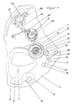
- an elevator lever 3 which can be pivoted about an axis 2, is mounted on a circuit board 1 and can be pivoted by actuating its actuating cam 4 by a path dependent on the currently displayed time of the watch.
- This path is determined by an hourly scale 5, which is rotatably driven by the clockwork and gradually increases in diameter, against which a pin 6 of the elevator lever 3 comes to rest and limits the swivel path.
- the elevator lever 3 has, concentrically to the axis, a toothed segment 7 which engages in an elevator drive gear 8 which is arranged on a spring core axis 9 in a rotationally fixed manner.
- the spring core axis 9 is rotatably mounted on the board 1.
- a spiral tension spring 10 enclosing the spring core axis 9 is fastened to the spring core axis 9.
- the other free end of the tension spring 10 is fixedly arranged on an annular spring barrel 11, which is freely rotatably mounted on the spring core axis 9 at a distance and radially encloses the spring core axis 9.
- the barrel 11 is designed as a ring gear 12 on its radially circumferential cylindrical outer surface.
- This biasing pinion 13, shown enlarged in FIGS. 3 and 4 has an adjusting pin 14, on the upper end face of which a slot 15 is formed, into which a screwdriver can be inserted and the biasing pinion can be rotated.
- a pretensioning pawl 17 is pivotally mounted on the circuit board 1 about a pivot axis 16.
- the biasing pawl 17 is designed as a two-armed lever, one free end of which has a toothed segment 18 which engages in the biasing pinion 13 in the blocking position shown. In this blocking position, the other free end rests against a stop 19 which is fixedly connected to the circuit board 1 and which prevents the pretensioning pawl 17 from pivoting further in the clockwise direction. against this stop 19, the biasing pawl 17 is acted upon by the free end of a spring arm 20, the other free end of which is attached to the circuit board 1.
- the pretensioning pawl 17 prevents the pretensioning pinion 13 and thus the barrel 11 from rotating in the relaxing direction of the tension spring 10.
- the pretensioning pawl 17 has a recess 21 into which a tool can be inserted.
- the preload pinion 13 is rotated clockwise by means of a screwdriver engaging in a slot 15. This leads to the spring housing 11 being rotated counterclockwise relative to the spring core axis 9 and thus to tensioning the tension spring 10.
- the biasing pawl 17 pivots counterclockwise and comes out of engagement with the toothed segment 18 from the biasing pinion 13.
- the pretensioning pawl 17 comes back into engagement with the pretensioning pinion 13 by slightly turning back the pretensioning pinion 13 and, after contact with the stop 19, blocks further relaxation of the tension spring 10 now having the desired pretension.
- the biasing pinion 13 is rotated clockwise by means of a screwdriver engaging in the slot 15 until the biasing pawl 17 is out of engagement with the biasing pinion.
- an hourly rake 22 shown offset, from whose teeth a scoop 23 can be pivoted.
- the latter pivots a pivotable hourly lever 24 against the force of a spring 26 and, after jumping over a tooth of the student rake 22, causes the hour hammer to strike a sound spring 27 and produce a tone.
Claims (13)
- Dispositif de remontage à ressort pour montre à répétition, destiné à actionner une sonnerie et comportant une roue dentée (8) de remontage, qui est calée sur un arbre (9) de barillet et qui peut être entraînée en rotation par un levier (3) de remontage à râteau (7), pouvant être manoeuvré manuellement ; un ressort spiral (10) de remontage, dont le bandage initial est réglable et qui est fixé par une extrémité à cet arbre (9) de barillet et par son autre extrémité à un barillet (11) qui entoure ledit arbre (9) à une certaine distance radiale, ainsi qu'un mécanisme de sonnerie qui est monté sur l'arbre (9) et par l'entremise duquel la sonnerie peut être actionnée, dispositif caractérisé en ce que le barillet (11) peut être amené au moyen d'un dispositif de réglage à un grand nombre de positions angulaires autour de l'arbre (9), positions dans lesquelles il peut être immobilisé.
- Dispositif de remontage à ressort selon la revendication 1, caractérisé en ce que le barillet (11) peut tourner aussi bien dans le sens qui bande le ressort (10) que dans le sens qui détend ce ressort (10).
- Dispositif de remontage selon l'une des revendications précédentes, caractérisé en ce que le barillet (11) peut être immobilisé, au moyen d'un dispositif de blocage de conformation complémentaire, qui peut être relié à ce barillet (11).
- Dispositif de remontage selon l'une des revendications précédentes, caractérisé en ce que le barillet (11) comporte une couronne dentée (12) périphérique, avec laquelle engrène un pignon (13) d'ajustage, qui peut être entraîné manuellement en rotation.
- Dispositif de remontage selon la revendication 4, caractérisé en ce que le pignon (13) est solidaire d'un tourillon (14), monté rotatif et qui peut être entraîné manuellement en rotation.
- Dispositif de remontage selon la revendication 5, caractérisé en ce que le tourillon (14) présente dans une face d'extrémité une encoche, dans laquelle un outil de forme complémentaire peut être inséré pour l'entraîner manuellement.
- Dispositif de remontage selon la revendication 6, caractérisé en ce que l'encoche est une fente (15) pour (recevoir) un tournevis.
- Dispositif de remontage selon l'une des revendications précédentes, caractérisé en ce que le dispositif de blocage comporte un cliquet (17), qui pivote sur un axe (16) et qui peut être déplacé entre une position de blocage, dans laquelle il est rendu solidaire par conformation du pignon (13), et une position de libération, dans laquelle ce pignon (13) peut tourner librement.
- Dispositif de remontage selon la revendication 8, caractérisé en ce que le cliquet (17) comporte à l'extrémité de l'un de ses bras un segment denté (18), qui vient en prise avec le pignon (13) dans la position de blocage et qu'il est possible de dégager de ce pignon (13) en faisant tourner ce dernier dans le sens qui bande le ressort (10).
- Dispositif de remontage selon la revendication 8, caractérisé en ce que, dans sa position de blocage, le cliquet (17) est appliqué contre une butée (19) fixe, qui l'empêche de pivoter et de faire tourner le pignon (13) dans le sens qui détend le ressort (10).
- Dispositif de remontage selon la revendication 10, caractérisé en ce que le cliquet (17) est sollicité élastiquement à sa position d'application contre la butée (19).
- Dispositif de remontage selon la revendication 8, caractérisé en ce que le cliquet (17) comporte une encoche, dans laquelle un outil de forme complémentaire peut être inséré pour le faire pivoter manuellement.
- Dispositif de remontage selon la revendication 12, caractérisé en ce que l'encoche est une fente (21) pour (recevoir) un tournevis.
Applications Claiming Priority (2)
| Application Number | Priority Date | Filing Date | Title |
|---|---|---|---|
| DE4012011 | 1990-04-13 | ||
| DE4012011A DE4012011A1 (de) | 1990-04-13 | 1990-04-13 | Zugfedereinrichtung |
Publications (2)
| Publication Number | Publication Date |
|---|---|
| EP0451336A1 EP0451336A1 (fr) | 1991-10-16 |
| EP0451336B1 true EP0451336B1 (fr) | 1993-12-15 |
Family
ID=6404370
Family Applications (1)
| Application Number | Title | Priority Date | Filing Date |
|---|---|---|---|
| EP90122015A Expired - Lifetime EP0451336B1 (fr) | 1990-04-13 | 1990-11-17 | Dispositif de remontage à ressort |
Country Status (2)
| Country | Link |
|---|---|
| EP (1) | EP0451336B1 (fr) |
| DE (2) | DE4012011A1 (fr) |
Families Citing this family (1)
| Publication number | Priority date | Publication date | Assignee | Title |
|---|---|---|---|---|
| EP1760548B1 (fr) | 2005-09-01 | 2008-12-03 | Montres Journe SA | Pièce d'horlogerie munie d'un mécanisme d'indication de l'heure par sonnerie |
Family Cites Families (3)
| Publication number | Priority date | Publication date | Assignee | Title |
|---|---|---|---|---|
| CH6339A (fr) * | 1893-02-28 | 1893-09-30 | Charles Morlet | Mécanisme perfectionné de montre à répétition |
| US940117A (en) * | 1908-12-03 | 1909-11-16 | Anders Aune | Watch. |
| CH1602875A4 (fr) * | 1975-01-23 | 1977-06-15 |
-
1990
- 1990-04-13 DE DE4012011A patent/DE4012011A1/de not_active Ceased
- 1990-11-17 DE DE90122015T patent/DE59003897D1/de not_active Expired - Fee Related
- 1990-11-17 EP EP90122015A patent/EP0451336B1/fr not_active Expired - Lifetime
Also Published As
| Publication number | Publication date |
|---|---|
| DE4012011A1 (de) | 1991-10-17 |
| DE59003897D1 (de) | 1994-02-03 |
| EP0451336A1 (fr) | 1991-10-16 |
Similar Documents
| Publication | Publication Date | Title |
|---|---|---|
| EP2034374B1 (fr) | Horloge | |
| EP1795976B1 (fr) | Pièce d'horlogerie | |
| DE60205763T2 (de) | Timepiece provided with striking mechanism | |
| EP1319997A1 (fr) | Dispositif à force constante | |
| DE2319907B2 (de) | Kalender-Schaltvorrichtung für Uhren | |
| DE602005005209T2 (de) | Vorrichtung zum Galoppschutz für Uhrenhemmung | |
| DE2936093A1 (de) | Zeitgesteuertes schloss | |
| DE2725514B2 (de) | Uhrwerk für eine Kalenderuhr | |
| EP0451336B1 (fr) | Dispositif de remontage à ressort | |
| DE1254088B (de) | Selbstaufzuguhr mit einem Planetengetriebe | |
| DE2109138C3 (de) | GroBuhrwerk mit Westminsterschlag oder dergl. Spielwerk und mittels Batterie angetriebenem Getriebemotor für das Schlagwerk | |
| DE2202846A1 (de) | Zeigerstell- und unruh-anhaltevorrichtung | |
| CH372983A (de) | Uhr mit Datumscheibe | |
| EP0931282B1 (fr) | Dispositif pour ajuster l'aiguille des minutes d'une montre comportant au moins une aiguille des minutes et une trotteuse | |
| DE1673623C (de) | Auslosevorrichtung fur Wieder holungswecker | |
| EP0451339B1 (fr) | Montre à répétition | |
| DE1523901C3 (de) | Vorrichtung zum Antrieb eines in seinem Lauf gehemmten Getriebes | |
| DE10061435C1 (de) | Oszillierende Säge für chirurgische Zwecke | |
| EP0451338B1 (fr) | Montre à répétition | |
| AT20771B (de) | Elektrische Uhr mit einer zum Anzeigen der Minuten mit den Zahlen von 0 bis 59 versehenen Scheibe. | |
| DE2502562B2 (de) | Anordnung zum verhindern der rueckdrehbewegung der triebfeder des federhauses von kleinuhren, insbesondere von armbanduhren | |
| DE1673729A1 (de) | Klinkengetriebe | |
| AT79882B (de) | Sicherheitsschloß für Fahrräder und dgl. Sicherheitsschloß für Fahrräder und dgl. | |
| DE264240C (fr) | ||
| DE2053502C (de) | Antriebseinrichtung eines Datumsan zeigers einer Uhr |
Legal Events
| Date | Code | Title | Description |
|---|---|---|---|
| PUAI | Public reference made under article 153(3) epc to a published international application that has entered the european phase |
Free format text: ORIGINAL CODE: 0009012 |
|
| 17P | Request for examination filed |
Effective date: 19910706 |
|
| AK | Designated contracting states |
Kind code of ref document: A1 Designated state(s): CH DE FR IT LI |
|
| 17Q | First examination report despatched |
Effective date: 19920928 |
|
| GRAA | (expected) grant |
Free format text: ORIGINAL CODE: 0009210 |
|
| AK | Designated contracting states |
Kind code of ref document: B1 Designated state(s): CH DE FR IT LI |
|
| PG25 | Lapsed in a contracting state [announced via postgrant information from national office to epo] |
Ref country code: IT Free format text: LAPSE BECAUSE OF FAILURE TO SUBMIT A TRANSLATION OF THE DESCRIPTION OR TO PAY THE FEE WITHIN THE PRE;WARNING: LAPSES OF ITALIAN PATENTS WITH EFFECTIVE DATE BEFORE 2007 MAY HAVE OCCURRED AT ANY TIME BEFORE 2007. THE CORRECT EFFECTIVE DATE MAY BE DIFFERENT FROM THE ONE RECORDED.SCRIBED TIME-LIMIT Effective date: 19931215 |
|
| ET | Fr: translation filed | ||
| REF | Corresponds to: |
Ref document number: 59003897 Country of ref document: DE Date of ref document: 19940203 |
|
| PLBE | No opposition filed within time limit |
Free format text: ORIGINAL CODE: 0009261 |
|
| STAA | Information on the status of an ep patent application or granted ep patent |
Free format text: STATUS: NO OPPOSITION FILED WITHIN TIME LIMIT |
|
| PG25 | Lapsed in a contracting state [announced via postgrant information from national office to epo] |
Ref country code: LI Effective date: 19941130 Ref country code: CH Effective date: 19941130 |
|
| 26N | No opposition filed | ||
| PG25 | Lapsed in a contracting state [announced via postgrant information from national office to epo] |
Ref country code: FR Effective date: 19950731 |
|
| REG | Reference to a national code |
Ref country code: CH Ref legal event code: PL |
|
| PG25 | Lapsed in a contracting state [announced via postgrant information from national office to epo] |
Ref country code: DE Effective date: 19950801 |
|
| REG | Reference to a national code |
Ref country code: FR Ref legal event code: ST |