EP0451336B1 - Mainspring assembly - Google Patents
Mainspring assembly Download PDFInfo
- Publication number
- EP0451336B1 EP0451336B1 EP90122015A EP90122015A EP0451336B1 EP 0451336 B1 EP0451336 B1 EP 0451336B1 EP 90122015 A EP90122015 A EP 90122015A EP 90122015 A EP90122015 A EP 90122015A EP 0451336 B1 EP0451336 B1 EP 0451336B1
- Authority
- EP
- European Patent Office
- Prior art keywords
- biasing
- mainspring
- mechanism according
- pinion
- pawl
- Prior art date
- Legal status (The legal status is an assumption and is not a legal conclusion. Google has not performed a legal analysis and makes no representation as to the accuracy of the status listed.)
- Expired - Lifetime
Links
Images


Classifications
-
- G—PHYSICS
- G04—HOROLOGY
- G04B—MECHANICALLY-DRIVEN CLOCKS OR WATCHES; MECHANICAL PARTS OF CLOCKS OR WATCHES IN GENERAL; TIME PIECES USING THE POSITION OF THE SUN, MOON OR STARS
- G04B1/00—Driving mechanisms
- G04B1/10—Driving mechanisms with mainspring
- G04B1/16—Barrels; Arbors; Barrel axles
-
- G—PHYSICS
- G04—HOROLOGY
- G04B—MECHANICALLY-DRIVEN CLOCKS OR WATCHES; MECHANICAL PARTS OF CLOCKS OR WATCHES IN GENERAL; TIME PIECES USING THE POSITION OF THE SUN, MOON OR STARS
- G04B21/00—Indicating the time by acoustic means
- G04B21/02—Regular striking mechanisms giving the full hour, half hour or quarter hour
- G04B21/12—Reiterating watches or clocks
Definitions
- the invention relates to a tension spring device of a repeater clock for driving a striking mechanism, with an elevator drive gear which is arranged in a rotationally fixed manner on a spring core axis and which can be rotatably driven by a manually pivotable elevator lift provided with a toothed segment, with a spiral tension spring which can be set with its pretension one end is attached to the spring core axis and the other end is attached to a barrel enclosing the spring core axis at a distance radially, with a striking mechanism drive arranged on the spring core axis, by means of which the striking mechanism can be driven.
- the tension spring is also prestressed in the non-opened position.
- a tension spring device of the type mentioned is known from CH-A 6339.
- the barrel is fixed on a board and the spring core axis can be adjusted in 45 ° steps to adjust the tension of the tension spring.
- a refinement of the preload setting by reducing the adjustment steps is not possible due to the small radial extent of the spring core axis.
- a repeater watch which has a spiral tension spring, the inner end of which is fastened to a spring core axis and the outer end of which is fastened to a spring housing enclosing the tension spring.
- the spring housing In order to tension the tension spring for a repetition process, the spring housing can be turned.
- the object of the invention is to provide a tension spring device of the type mentioned at the outset, which enables an exact fine adjustment of the pretension of the tension spring.
- the barrel is rotatably adjustable by means of an adjusting device about the innerspring axis in a plurality of non-rotatable positions.
- This design enables the tension of the tension spring to be set only when the entire impact and elevator device is completely assembled. Influences due to manufacturing and assembly tolerances can thus be fully compensated and the tension spring can be provided with an optimal preload, which ensures largely the same power output over the entire working range of the tension spring. This leads to an even rhythm of the tones generated by the striking mechanism.
- the tension spring can e.g. Repair purposes can be relaxed again.
- the fine adjustment of the tension of the tension spring according to the invention is also possible.
- the barrel can be blocked by means of a locking device which can be positively connected to the barrel, for which purpose the barrel can have a radially circumferential ring gear in a simple configuration, into which a preload pinion which can be driven manually rotates engages.
- a locking device which can be positively connected to the barrel
- the barrel can have a radially circumferential ring gear in a simple configuration, into which a preload pinion which can be driven manually rotates engages. This enables the tension of the tension spring to be adjusted continuously.
- the preload pinion can be arranged in a rotationally fixed manner on a rotatably mounted adjusting pin which can be rotated manually.
- the adjusting pin has on one end face a recess into which a tool can be positively inserted for manual drive, the pre-tensioning of the tension spring can be set in a simple manner. This is particularly easy if the recess is a slot for a screwdriver.
- the blocking device can be pivoted about a pivot axis ...
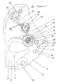
- an elevator lever 3 which can be pivoted about an axis 2, is mounted on a circuit board 1 and can be pivoted by actuating its actuating cam 4 by a path dependent on the currently displayed time of the watch.
- This path is determined by an hourly scale 5, which is rotatably driven by the clockwork and gradually increases in diameter, against which a pin 6 of the elevator lever 3 comes to rest and limits the swivel path.
- the elevator lever 3 has, concentrically to the axis, a toothed segment 7 which engages in an elevator drive gear 8 which is arranged on a spring core axis 9 in a rotationally fixed manner.
- the spring core axis 9 is rotatably mounted on the board 1.
- a spiral tension spring 10 enclosing the spring core axis 9 is fastened to the spring core axis 9.
- the other free end of the tension spring 10 is fixedly arranged on an annular spring barrel 11, which is freely rotatably mounted on the spring core axis 9 at a distance and radially encloses the spring core axis 9.
- the barrel 11 is designed as a ring gear 12 on its radially circumferential cylindrical outer surface.
- This biasing pinion 13, shown enlarged in FIGS. 3 and 4 has an adjusting pin 14, on the upper end face of which a slot 15 is formed, into which a screwdriver can be inserted and the biasing pinion can be rotated.
- a pretensioning pawl 17 is pivotally mounted on the circuit board 1 about a pivot axis 16.
- the biasing pawl 17 is designed as a two-armed lever, one free end of which has a toothed segment 18 which engages in the biasing pinion 13 in the blocking position shown. In this blocking position, the other free end rests against a stop 19 which is fixedly connected to the circuit board 1 and which prevents the pretensioning pawl 17 from pivoting further in the clockwise direction. against this stop 19, the biasing pawl 17 is acted upon by the free end of a spring arm 20, the other free end of which is attached to the circuit board 1.
- the pretensioning pawl 17 prevents the pretensioning pinion 13 and thus the barrel 11 from rotating in the relaxing direction of the tension spring 10.
- the pretensioning pawl 17 has a recess 21 into which a tool can be inserted.
- the preload pinion 13 is rotated clockwise by means of a screwdriver engaging in a slot 15. This leads to the spring housing 11 being rotated counterclockwise relative to the spring core axis 9 and thus to tensioning the tension spring 10.
- the biasing pawl 17 pivots counterclockwise and comes out of engagement with the toothed segment 18 from the biasing pinion 13.
- the pretensioning pawl 17 comes back into engagement with the pretensioning pinion 13 by slightly turning back the pretensioning pinion 13 and, after contact with the stop 19, blocks further relaxation of the tension spring 10 now having the desired pretension.
- the biasing pinion 13 is rotated clockwise by means of a screwdriver engaging in the slot 15 until the biasing pawl 17 is out of engagement with the biasing pinion.
- an hourly rake 22 shown offset, from whose teeth a scoop 23 can be pivoted.
- the latter pivots a pivotable hourly lever 24 against the force of a spring 26 and, after jumping over a tooth of the student rake 22, causes the hour hammer to strike a sound spring 27 and produce a tone.
Description
Die Erfindung bezieht sich auf eine Zugfedereinrichtung einer Repetieruhr zum Antrieb eines Schlagwerkes, mit einem auf einer Federkernachse drehfest angeordneten Aufzugstriebzahnrad, das von einem mit einem Zahnsegment versehenen manuell schwenkbar antreibbaren Aufzugshebe drehbar antreibbar ist, mit einer spiralförmigen, mit ihrer Vorspannung einstellbaren Zugfeder, die mit ihrem einen Ende an der Federkernachse und mit ihrem anderen Ende an einem die Federkernachse in einem Abstand radial umschließenden Federhaus befestigt ist, mit einem auf der Federkernachse angeordneten Schlagwerkantrieb, durch den das Schlagwerk antreibbar ist.The invention relates to a tension spring device of a repeater clock for driving a striking mechanism, with an elevator drive gear which is arranged in a rotationally fixed manner on a spring core axis and which can be rotatably driven by a manually pivotable elevator lift provided with a toothed segment, with a spiral tension spring which can be set with its pretension one end is attached to the spring core axis and the other end is attached to a barrel enclosing the spring core axis at a distance radially, with a striking mechanism drive arranged on the spring core axis, by means of which the striking mechanism can be driven.
Bei derartigen Zugfedereinrichtungen ist die Zugfeder auch in der nicht aufgezogenen Stellung vorgespannt. Es ist aber schwierig bei der Montage der Uhr der Zugfeder die gewünschte Vorspannung zu geben.In tension spring devices of this type, the tension spring is also prestressed in the non-opened position. However, it is difficult to give the tension spring the desired preload when assembling the clock.
Eine Zugfedereinrichtung der eingangs genannten Art ist aus der CH-A 6339 bekannt. Dabei ist das Federhaus fest auf einer Platine angeordnet und die Federkernachse in 45°- Schritten zur Vorspannungseinstellung der Zugfeder verstellbar.A tension spring device of the type mentioned is known from CH-A 6339. The barrel is fixed on a board and the spring core axis can be adjusted in 45 ° steps to adjust the tension of the tension spring.
Eine Verfeinerung der Vorspannungseinstellung durch Verkleinerung der Verstellschritte ist aufgrund der geringen radialen Erstreckung der Federkernachse nicht möglich.A refinement of the preload setting by reducing the adjustment steps is not possible due to the small radial extent of the spring core axis.
Aus der US-A-940 117 ist zur Sicherung der Vorspannung einer Feder eine Blockiereinrichtung mit einer um eine Schweckachse schwenkbaren Vorspannklinke bekannt, durch die ein Federrad blockierbar ist.From US-A-940 117 a locking device with a biasing pawl pivotable about a pivot axis is known to secure the bias of a spring, by means of which a spring wheel can be locked.
Weiterhin ist aus der FR-A-22 98 815 eine Repetieruhr bekannt, die eine spiralförmige Zugfeder aufweist, deren inneres Ende an einer Federkernachse und deren äußeres Ende an einem die Zugfeder umschließenden Federgehäuse befestigt ist. Um die Zugfeder für einen Repetitionsvorgang zu spannen, ist das Federgehäuse verdrehbar.Furthermore, from FR-A-22 98 815, a repeater watch is known which has a spiral tension spring, the inner end of which is fastened to a spring core axis and the outer end of which is fastened to a spring housing enclosing the tension spring. In order to tension the tension spring for a repetition process, the spring housing can be turned.
Aufgabe der Erfindung ist es eine Zugfedereinrichtung der eingangs genannten Art zu schaffen, die eine exakte Feineinstellung der Vorspannung der Zugfeder ermöglicht.The object of the invention is to provide a tension spring device of the type mentioned at the outset, which enables an exact fine adjustment of the pretension of the tension spring.
Diese Aufgabe wird erfindungsgemäß dadurch gelöst, daß das Federhauss mittels einer Stellvorrichtung um die Federkernachse in eine Vielzahl von drehfest blockierbaren Positionen drehbar einstellbar ist. Diese Ausbildung ermöglicht es die Vorspannung der Zugfeder erst dann einzustellen wenn die gesamte Schlag- und Aufzugseinrichtung komplett montiert ist. Einflüsse durch Herstellungs- und Montagetoleranzen können somit vollständig kompensiert und die Zugfeder mit einer optimalen Vorspannung versehen werden, die eine weitgehend gleiche Kraftabgabe über den ganzen genutzten Arbeitsbereich der Zugfeder gewährleistet. Dies führt zu einem gleichmäßigen Rhythmus der von dem Schlagwerk erzeugten Töne.This object is achieved in that the barrel is rotatably adjustable by means of an adjusting device about the innerspring axis in a plurality of non-rotatable positions. This design enables the tension of the tension spring to be set only when the entire impact and elevator device is completely assembled. Influences due to manufacturing and assembly tolerances can thus be fully compensated and the tension spring can be provided with an optimal preload, which ensures largely the same power output over the entire working range of the tension spring. This leads to an even rhythm of the tones generated by the striking mechanism.
Ist das Federhaus sowohl in die die Zugfeder spannende als auch in die die Zugfeder entspannende Richtung drehbar, so kann die Zugfeder z.B. Reparaturzwecke wieder entspannt werden. Außerdem ist damit auch die erfindungsgemässe Feineinstellung der Vorspannung der Zugfeder möglich.If the barrel can be rotated both in the direction that tensions the tension spring and in the direction that relaxes the tension spring, the tension spring can e.g. Repair purposes can be relaxed again. In addition, the fine adjustment of the tension of the tension spring according to the invention is also possible.
Vorzugsweise ist das Federhaus mittels einer formschlüssig mit dem Federhaus verbindbaren Blockiereinrichtung blockierbar, wozu in einfacher Ausbildung das Federhaus einen radial umlaufenden Zahnkranz aufweisen kann, in den ein manuell drehbar antreibbares Vorspannritzel eingreift. Dadurch ist die Einstellung der Vorspannung der Zugfeder sogar stufenlos möglich.Preferably, the barrel can be blocked by means of a locking device which can be positively connected to the barrel, for which purpose the barrel can have a radially circumferential ring gear in a simple configuration, into which a preload pinion which can be driven manually rotates engages. This enables the tension of the tension spring to be adjusted continuously.
Das Vorspannritzel kann dazu drehfest auf einem drehbar gelagerten Stellzapfen angeordnet sein der manuell drehbar antreibbar ist.For this purpose, the preload pinion can be arranged in a rotationally fixed manner on a rotatably mounted adjusting pin which can be rotated manually.
Weist der Stellzapfen an seiner einen Stirnseite eine Ausnehmung auf, in die ein Werkzeug formschlüssig zum manuellen Antrieb einssetzbar ist, so kann auf einfache Weise die Vorspannung der Zugfeder eingestellt werden. Dies ist besonders einfach möglich, wenn die Ausnehmung ein Schlitz für einen Schraubendreher ist.If the adjusting pin has on one end face a recess into which a tool can be positively inserted for manual drive, the pre-tensioning of the tension spring can be set in a simple manner. This is particularly easy if the recess is a slot for a screwdriver.
Zur Sicherung der eingestellten Federvorspannung kann die Blockiereinrichtung eine um eine Schwenkachse schwenkbare...To secure the set spring preload, the blocking device can be pivoted about a pivot axis ...
Vorspannklinke aufweisen, die zwischen einer Blockierposition, in der die Vorspannklinke formschlüssig mit dem Vorspannritzel verbunden ist, und einer Freigabeposition, in der das Vorspannritzel frei drehbar ist bewegbar ist. Dazu kann die Vorspannklinke an ihrem einen freien Ende ein Zahnsegment aufweisen, das in der Blockierposition in das Vorspannritzel eingreift und durch Drehung des Vorspannritzels in die die Zugfeder spannende Richtung außer Eingriff vom Vorspannritzel schwenkbar ist.
Ein Zurückdrehen des Vorspannritzels durch die Vorspannung der Zugfeder wird dadurch verhindert, daß die Vorspannklinke in der Blockierposition an einem festen Anschlag in Anlage ist, durch den ein Schwenken der Vorspannklinke und ein Drehen des Vorspannritzels in die die Zugfeder entspannende Richtung blockierbar ist. Zur definierten Lage der Vorspannklinke in der Blockierposition kann die Vorspannklinke zur Anlage an dem Anschlag federbeaufschlagt sein.
Um ein Zurückstellen des Vorspannritzels und damit ein Entspannen der Zugfeder zu ermöglichen kann die Vorspannklinke eine Ausnehmung aufweisen, in die ein Werkzeug formschlüssig zum manuellen Schwenkantrieb einsetzbar ist, wobei in einfacher Weise die Ausnehmung ein Schlitz für einen Schraubendreher sein kann. Damit kann die Vorspannklinke in der Freigabeposition festgehalten und das Vorspannritzel ungehindert in die die Zugfeder entspannende Richtung verdreht werden.
Ein Ausführungsbeispiel der Erfindung ist in der Zeichnung dargestellt und wird im folgenden näher beschrieben. Es zeigen:
- Figur 1
- eine Draufsicht auf das Schlagwerk und dessen Aufzugseinrichtung einer Repetieruhr
Figur 2- einen Querschnitt der Zugfedereinrichtung der Repetieruhr nach Figur 1
Figur 3- eine Seitenansicht des Vorspannritzels nach Figur 1
Figur 4- eine Draufsicht des Vorspannritzels nach
Figur 3
A turning back of the pretension pinion due to the pretensioning of the tension spring is prevented in that the pretensioning pawl is in contact with a fixed stop in the blocking position, by means of which a pivoting of the pretensioning pawl and a turning of the pretensioning pinion in the direction relaxing the tension spring can be blocked. For the defined position of the pretensioning pawl in the blocking position, the pretensioning pawl can be spring-loaded to bear against the stop.
In order to enable a resetting of the preload pinion and thus a relaxation of the tension spring, the preload pawl can have a recess into which a tool can be positively inserted for the manual swivel drive, the recess being able to be a slot for a screwdriver in a simple manner. This allows the pretensioning pawl to be held in the release position and the pretensioning pinion to be rotated unhindered in the direction that relaxes the tension spring.
An embodiment of the invention is shown in the drawing and will be described in more detail below. Show it:
- Figure 1
- a plan view of the striking mechanism and its elevator device of a repeater clock
- Figure 2
- 2 shows a cross section of the tension spring device of the repeater clock according to FIG. 1
- Figure 3
- a side view of the preload pinion of Figure 1
- Figure 4
- a plan view of the preload pinion according to Figure 3
In Figur 1 ist auf einer Platine 1 ein um eine Achse 2 schwenkbarer Aufzugshebel 3 gelagert, der durch Beaufschlagung seines Betätigungsnockens 4 um einen von der momentanen angezeigten Zeit der Uhr abhängigen Weg schwenkbar ist. Dieser Weg wird von einer von dem Uhrwerk drehbar angetriebenen spiralartig sich stufenweise im Durchmesser vergrößernden Stundenstaffel 5 bestimmt, an der ein Stift 6 des Aufzugshebels 3 zur Anlage kommt und den Schwenkweg begrenzt. Der Aufzugshebel 3 besitzt konzentrisch zur Achse ein Zahnsegment 7 das in ein Aufzugstriebzahnrad 8 eingreift, welches auf einer Federkernachse 9 drehfest angeordnet ist. Die Federkernachse 9 ist drehbar auf der Platine 1 gelagert.
Mit ihrem einen freien Ende ist eine spiralförmige die Federkernachse 9 umschließende Zugfeder 10 an der Federkernachse 9 befestigt. Das andere freie Ende der Zugfeder 10 ist an einem an der Federkernachse 9 frei drehbar gelagerten die Federkernachse 9 in einem Abstand radial umschließenden ringförmigen Federhaus 11 fest angeordnet. An seiner radial umlaufenden zylindrischen Mantelfläche ist das Federhaus 11 als Zahnkranz 12 ausgebildet. In diesen Zahnkranz 12 greift ein frei drehbar auf der Platine 1 gelagertes Vorspannritzel 13 ein. Dieses in den Figuren 3 und 4 vergrößert dargestellte Vorspannritzel 13 besitzt einen Stellzapfen 14, an dessen oberer Stirnseite ein Schlitz 15 ausgebildet ist, in den ein Schraubendreher einsetzbar und das Vorspannritzel verdrehbar ist.In FIG. 1, an
With its one free end, a
Um eine Schwenkachse 16 ist eine Vorspannklinke 17 schwenkbar auf der Platine 1 gelagert. Die Vorspannklinke 17 ist als zweiarmiger Hebel ausgebildet, dessen eines freies Ende ein Zahnsegment 18 aufweist, das in der dargestellten Blockierposition in das Vorspannritzel 13 eingreift. In dieser Blockierposition liegt das andere freie Ende an einem ortsfest mit der Platine 1 verbundenen Anschlag 19 an, der ein Weiterverschwenken der Vorspannklinke 17 im Uhrzeigersinn verhindert. Gegen diesen Anschlag 19 ist die Vorspannklinke 17 durch das freie Ende eines Federarms 20 beaufschlagt, dessen anderes freies Ende an der Platine 1 befestigt ist. In dieser Lage verhindert die Vorspannklinke 17 ein Verdrehen des Vorspannritzels 13 und damit des Federhauses 11 in entspannender Richtung der Zugfeder 10. Zum manuellen Verschwenken besitzt die Vorspannklinke 17 eine Aussparung 21, in den ein Werkzeug einsetzbar ist. Um der Zugfeder 10 die erforderliche Vorspannung zu geben wird mittels eines in einen Schlitz 15 eingreifenden Schraubendrehers das Vorspannritzel 13 im Uhrzeigersinn verdreht. Dies führt zum Verdrehen des Federgehäuses 11 entgegen dem Uhrzeigersinn relativ zur Federkernachse 9 und damit zum Spannen der Zugfeder 10.
Die Vorspannklinke 17 schwenkt dabei gegen den Uhrzeigersinn und kommt mit ihrem Zahnsegment 18 außer Eingriff vom Vorspannritzel 13.
Ist die gewünschte Vorspannung der Zugfeder 10 leicht überschritten gelangt durch leichtes Zurückdrehen des Vorspannritzels 13 die Vorspannklinke 17 wieder in Eingriff mit dem Vorspannritzel 13 und blockiert nach Anlage am Anschlag 19 ein weiteres Entspannen der nunmehr die gewünschte Vorspannung aufweisenden Zugfeder 10.A
The
If the desired pretensioning of the
Soll ein Entspannen der Zugfeder 10 erfolgen, wird mittels eines in den Schlitz 15 eingreifenden Schraubenziehers das Vorspannritzel 13 im Uhrzeigersinn gedreht, bis die Vorspannklinke 17 ausser Eingriff mit dem Vorspannritzel ist.If the
Dann wird mit einem Werkzeug wie z.B. einem einfachen Stift die Vorspannklinke 17 in deren Öffnung 21 festgehalten und das Vorspannritzel 13 entgegen dem Uhrzeigersinn gedreht, bis die Zugfeder 10 entspannt ist.Then with a tool such as a simple pin, the biasing
Auf der Federkernachse 9 ebenfalls drehfest angeordnet ist ein der Übersichtlichkeit wegen versetzt dargestellter Stundenrechen 22, von dessen Zähnen ein Schöpfer 23 schwenkbar ist. Entsprechend der Schwenkvorgänge des Schöpfers 23 verschwenkt dieser über einen schwenkbar gelagerten Stundenzwischenhebel 24 einen ebenfalls schwenkbar gelagerten Stundenhammer 25 entgegen der Kraft einer Feder 26 und läßt nach Überspringen eines Zahns des Studenrechens 22 den Stundenhammer auf eine Tonfeder 27 aufschlagen und einen Ton erzeugen.On the
Claims (13)
- Mainspring mechanism on a repeater for operating a striking train, having a toothed driving wheel (8) disposed, locked against rotation, on a barrel arbor (9) and adapted to be driven in rotation by a power lever (3) adapted to be driven by manually swivelling it and provided with a toothed quadrant (7), further having a spiral mainspring (10) with adjustable bias, one end of which is attached to the barrel arbor (9) and the other end of which is attached to a spring box (11) which encloses the barrel arbor (9) radially with clearance, and further having a striking train drive disposed on the barrel arbor (9) and used to operate the striking train, characterised in that the spring box (11) can be adjusted by means of a final-control device so as to rotate about the barrel arbor (9) into a large number of positions that can be locked against rotation.
- Mainspring mechanism according to claim 1, characterised in that the spring box (11) is able to rotate both in the direction tensioning the mainspring (10) and in the direction relaxing the mainspring (10).
- Mainspring mechanism according to either of the preceding claims, characterised in that the spring box (11) is adapted to be locked by means of a locking device that can be positively connected to the spring box (11).
- Mainspring mechanism according to any of the preceding claims, characterised in that the spring box (11) is surrounded radially by a toothed ring (12) into which engages a biasing pinion (13) adapted to be operated by manual rotation.
- Mainspring mechanism according to claim 4, characterised in that the biasing pinion (13) is disposed, locked against rotation, on a final-control pin (14) which is rotatably mounted and adapted to be operated by manual rotation.
- Mainspring mechanism according to claim 5, characterised in that on one end face the final-control pin (14) incorporates a recess into which a tool can be positively inserted for operating it by manual rotation.
- Mainspring mechanism according to claim 6, characterised in that the recess is a slot (15) for a screwdriver.
- Mainspring mechanism according to any of the preceding claims, characterised in that the locking device incorporates a biasing pawl (17) adapted to be swivelled about a swivel axis (16) and adapted to move between a locking position in which the biasing pawl (17) is positively operated to the biasing pinion (13) and a release position in which the biasing pinion (13) is free to rotate.
- Mainspring mechanism according to claim 8, characterised in that at one free end the biasing pawl (17) incorporates a toothed quadrant (18) which in the locking position engages in the biasing pinion (13) and by rotation of the biasing pinion (13) can be swivelled out of engagement with the biasing pinion (13) in the direction tensioning the mainspring (10).
- Mainspring mechanism according to claim 8, characterised in that in the locking position the biasing pawl (17) rests against a fixed stop (19) used to lock the biasing pawl (17) against swivelling and the biasing pinion (13) against rotation in the direction relaxing the mainspring (10).
- Mainspring mechanism according to claim 10, characterised in that the biasing pawl (17) is spring-operated to keep it resting against the stop (19).
- Mainspring mechanism according to claim 8, characterised in that the biasing pawl (17) incorporates a recess into which a tool can be positively inserted for operating it by manual swivelling.
- Mainspring according to claim 12, characterised in that the recess is a slot (21) for a screwdriver.
Applications Claiming Priority (2)
| Application Number | Priority Date | Filing Date | Title |
|---|---|---|---|
| DE4012011A DE4012011A1 (en) | 1990-04-13 | 1990-04-13 | TENSION SPRING |
| DE4012011 | 1990-04-13 |
Publications (2)
| Publication Number | Publication Date |
|---|---|
| EP0451336A1 EP0451336A1 (en) | 1991-10-16 |
| EP0451336B1 true EP0451336B1 (en) | 1993-12-15 |
Family
ID=6404370
Family Applications (1)
| Application Number | Title | Priority Date | Filing Date |
|---|---|---|---|
| EP90122015A Expired - Lifetime EP0451336B1 (en) | 1990-04-13 | 1990-11-17 | Mainspring assembly |
Country Status (2)
| Country | Link |
|---|---|
| EP (1) | EP0451336B1 (en) |
| DE (2) | DE4012011A1 (en) |
Families Citing this family (1)
| Publication number | Priority date | Publication date | Assignee | Title |
|---|---|---|---|---|
| DE602005011433D1 (en) | 2005-09-01 | 2009-01-15 | Montres Journe S A | Clock with a timekeeping device by bell |
Family Cites Families (3)
| Publication number | Priority date | Publication date | Assignee | Title |
|---|---|---|---|---|
| CH6339A (en) * | 1893-02-28 | 1893-09-30 | Charles Morlet | Advanced repeater watch mechanism |
| US940117A (en) * | 1908-12-03 | 1909-11-16 | Anders Aune | Watch. |
| CH596590B5 (en) * | 1975-01-23 | 1978-03-15 | Pforzheimer Uhren Rohwerke |
-
1990
- 1990-04-13 DE DE4012011A patent/DE4012011A1/en not_active Ceased
- 1990-11-17 EP EP90122015A patent/EP0451336B1/en not_active Expired - Lifetime
- 1990-11-17 DE DE90122015T patent/DE59003897D1/en not_active Expired - Fee Related
Also Published As
| Publication number | Publication date |
|---|---|
| DE4012011A1 (en) | 1991-10-17 |
| EP0451336A1 (en) | 1991-10-16 |
| DE59003897D1 (en) | 1994-02-03 |
Similar Documents
| Publication | Publication Date | Title |
|---|---|---|
| EP2034374B1 (en) | Clock | |
| EP1795976B1 (en) | Timepiece | |
| DE60205763T2 (en) | Timepiece provided with striking mechanism | |
| EP1319997A1 (en) | Constant force device | |
| DE2319907B2 (en) | Calendar switching device for clocks | |
| DE602005005209T2 (en) | Device for gallop protection for clock escapement | |
| DE2936093A1 (en) | TIME-LOCKED LOCK | |
| DE2725514B2 (en) | Movement for a calendar watch | |
| EP0451336B1 (en) | Mainspring assembly | |
| DE1254088B (en) | Self-winding watch with a planetary gear | |
| DE2109138C3 (en) | Large clockwork with Westminster chime or similar mechanism and battery-driven gear motor for the striking mechanism | |
| DE2202846A1 (en) | POINTERS AND RUN-STOP DEVICE | |
| CH372983A (en) | Clock with date disc | |
| EP0931282B1 (en) | Device for regulating the minute hand of a clock having at least a minute hand and a second hand | |
| DE1673623C (en) | Triggering device for repeating alarm clocks | |
| EP0451339B1 (en) | Repeating watch | |
| DE1523901C3 (en) | Device for driving a gear jammed in its course | |
| DE10061435C1 (en) | Surgical oscillating saw has sawblade clamped between carrier surface of oscillating hollow shaft and clamp surface of axially displaced armature | |
| EP0451338B1 (en) | Repeating watch | |
| AT20771B (en) | Electric clock with a disc with the numbers from 0 to 59 showing the minutes. | |
| DE2502562B2 (en) | ARRANGEMENT TO PREVENT THE RETURN MOVEMENT OF THE SPRING OF THE SPRING HOUSE OF SMALL WATCHES, IN PARTICULAR WRISTWATCHES | |
| DE1673729A1 (en) | Ratchet gears | |
| AT79882B (en) | Safety lock for bicycles and the like. Safety lock for bicycles and the like. | |
| DE264240C (en) | ||
| DE2053502C (en) | Drive device of a date display of a clock |
Legal Events
| Date | Code | Title | Description |
|---|---|---|---|
| PUAI | Public reference made under article 153(3) epc to a published international application that has entered the european phase |
Free format text: ORIGINAL CODE: 0009012 |
|
| 17P | Request for examination filed |
Effective date: 19910706 |
|
| AK | Designated contracting states |
Kind code of ref document: A1 Designated state(s): CH DE FR IT LI |
|
| 17Q | First examination report despatched |
Effective date: 19920928 |
|
| GRAA | (expected) grant |
Free format text: ORIGINAL CODE: 0009210 |
|
| AK | Designated contracting states |
Kind code of ref document: B1 Designated state(s): CH DE FR IT LI |
|
| PG25 | Lapsed in a contracting state [announced via postgrant information from national office to epo] |
Ref country code: IT Free format text: LAPSE BECAUSE OF FAILURE TO SUBMIT A TRANSLATION OF THE DESCRIPTION OR TO PAY THE FEE WITHIN THE PRE;WARNING: LAPSES OF ITALIAN PATENTS WITH EFFECTIVE DATE BEFORE 2007 MAY HAVE OCCURRED AT ANY TIME BEFORE 2007. THE CORRECT EFFECTIVE DATE MAY BE DIFFERENT FROM THE ONE RECORDED.SCRIBED TIME-LIMIT Effective date: 19931215 |
|
| ET | Fr: translation filed | ||
| REF | Corresponds to: |
Ref document number: 59003897 Country of ref document: DE Date of ref document: 19940203 |
|
| PLBE | No opposition filed within time limit |
Free format text: ORIGINAL CODE: 0009261 |
|
| STAA | Information on the status of an ep patent application or granted ep patent |
Free format text: STATUS: NO OPPOSITION FILED WITHIN TIME LIMIT |
|
| PG25 | Lapsed in a contracting state [announced via postgrant information from national office to epo] |
Ref country code: LI Effective date: 19941130 Ref country code: CH Effective date: 19941130 |
|
| 26N | No opposition filed | ||
| PG25 | Lapsed in a contracting state [announced via postgrant information from national office to epo] |
Ref country code: FR Effective date: 19950731 |
|
| REG | Reference to a national code |
Ref country code: CH Ref legal event code: PL |
|
| PG25 | Lapsed in a contracting state [announced via postgrant information from national office to epo] |
Ref country code: DE Effective date: 19950801 |
|
| REG | Reference to a national code |
Ref country code: FR Ref legal event code: ST |