EP0450397B1 - Dispositif d'écran pour sectionneur de puissance - Google Patents
Dispositif d'écran pour sectionneur de puissance Download PDFInfo
- Publication number
- EP0450397B1 EP0450397B1 EP91104289A EP91104289A EP0450397B1 EP 0450397 B1 EP0450397 B1 EP 0450397B1 EP 91104289 A EP91104289 A EP 91104289A EP 91104289 A EP91104289 A EP 91104289A EP 0450397 B1 EP0450397 B1 EP 0450397B1
- Authority
- EP
- European Patent Office
- Prior art keywords
- chamber
- wall
- switch according
- circuit breaker
- drive housing
- Prior art date
- Legal status (The legal status is an assumption and is not a legal conclusion. Google has not performed a legal analysis and makes no representation as to the accuracy of the status listed.)
- Expired - Lifetime
Links
- 239000011810 insulating material Substances 0.000 claims description 4
- 239000012212 insulator Substances 0.000 claims 10
- 238000009413 insulation Methods 0.000 description 7
- 238000010276 construction Methods 0.000 description 2
- 238000004519 manufacturing process Methods 0.000 description 2
- 238000005192 partition Methods 0.000 description 2
- 230000002411 adverse Effects 0.000 description 1
- 230000004323 axial length Effects 0.000 description 1
- 239000004020 conductor Substances 0.000 description 1
- 238000001816 cooling Methods 0.000 description 1
- 238000003780 insertion Methods 0.000 description 1
- 230000037431 insertion Effects 0.000 description 1
- 238000000034 method Methods 0.000 description 1
- 239000000047 product Substances 0.000 description 1
- 239000011265 semifinished product Substances 0.000 description 1
Images

Classifications
-
- H—ELECTRICITY
- H01—ELECTRIC ELEMENTS
- H01H—ELECTRIC SWITCHES; RELAYS; SELECTORS; EMERGENCY PROTECTIVE DEVICES
- H01H33/00—High-tension or heavy-current switches with arc-extinguishing or arc-preventing means
- H01H33/60—Switches wherein the means for extinguishing or preventing the arc do not include separate means for obtaining or increasing flow of arc-extinguishing fluid
- H01H33/66—Vacuum switches
- H01H33/666—Operating arrangements
-
- H—ELECTRICITY
- H01—ELECTRIC ELEMENTS
- H01H—ELECTRIC SWITCHES; RELAYS; SELECTORS; EMERGENCY PROTECTIVE DEVICES
- H01H9/00—Details of switching devices, not covered by groups H01H1/00 - H01H7/00
- H01H9/52—Cooling of switch parts
- H01H2009/526—Cooling of switch parts of the high voltage switches
-
- H—ELECTRICITY
- H01—ELECTRIC ELEMENTS
- H01H—ELECTRIC SWITCHES; RELAYS; SELECTORS; EMERGENCY PROTECTIVE DEVICES
- H01H33/00—High-tension or heavy-current switches with arc-extinguishing or arc-preventing means
- H01H33/60—Switches wherein the means for extinguishing or preventing the arc do not include separate means for obtaining or increasing flow of arc-extinguishing fluid
- H01H33/66—Vacuum switches
- H01H33/666—Operating arrangements
- H01H2033/6665—Details concerning the mounting or supporting of the individual vacuum bottles
Definitions
- the invention relates to a support switch according to the preamble of the first claim (see e.g. DE-U-8028797).
- the chamber has a holding wall which is spaced apart from its rear wall and which is fixed to the drive housing.
- a drive linkage for transmitting a switching movement from a drive in the switch housing to a switching lever provided on the circuit breaker is located between the holding wall and the rear wall of the chamber.
- the circuit breaker which is designed as a vacuum interrupter, has connection pieces at the top and bottom which are fastened on supports connected to the rear wall.
- the connectors are also supported on the front by a rigid insulating rod.
- the chamber also has integral upper and lower end walls connected to the other side walls, in which openings are provided for ensuring a convective cooling air flow for the circuit breaker.
- the bowl-shaped structure with the special rear space for the passage of a switching rod makes it necessary to manufacture the chambers individually in tools with mold cores which are to be pulled perpendicular to one another, and in addition an independent cover has to be provided in order to achieve a surrounding insulation. Do that between the rest Chamber existing column is not a continuous insulation.
- the front support rod between the connectors to the lid takes up additional space.
- the invention has for its object to take measures in a support switch according to the preamble of the first claim, through which a simplified manufacture of the chamber is possible with a compact design.
- the chamber can be manufactured from a semi-finished profile product, which is manufactured in a continuous drawing process, for example from a fiber-reinforced duomer by the meter. From this profile semi-finished product only a piece needs to be cut off according to the required chamber length.
- the semi-finished profile contains the necessary holding means in the form of holding strips that run in the longitudinal direction and are provided at least in the area of the rear wall of the chamber.
- the front-side holding means can be formed either by the front wall of the chamber which is integrally connected to the other jacket walls of the chamber or by further moving holding strips provided in the area thereof.
- the connecting pieces can then be fixed directly on these mounting means, so that a compact construction is possible.
- the chamber is designed to be gap-free in the circumferential direction and only needs to have openings there on the front side insofar as they are required for holding or leading out the connecting pieces.
- the chamber formed in this way also has a high mechanical strength and very good insulation properties.
- the chamber side walls can the level of the front chamber front wall must be brought forward so that the partition function is achieved in the area of the bare connections projecting outwards.
- These advanced ribs also run in the longitudinal direction with the drawn profile and can therefore be formed in one piece.
- the chamber side walls can also be pulled back over the rear side wall and provided at their ends with angled tab strips that can be attached to the side wall of the drive housing.
- the distance between the tab strips or the rear holding strips from the rear wall of the chamber is dimensioned in accordance with the required dielectric strengths of the insulation sections.
- fastening tabs on the connecting pieces which are applied from the rear wall of the chamber to the adjacent holding strips or to the front wall of the chamber.
- the circuit breaker with the connectors attached to it can thus be inserted in the longitudinal direction of the chamber profile so that the rear fastening tabs engage in the space between the holding strip arranged there and the chamber rear wall, there being sufficient free space for the fastening tabs towards the rear wall. A corresponding amount of space is then also available between the fastening tabs on the front and the brackets provided there.
- the circuit breakers provided with the connecting pieces can thus be conveniently inserted into the chamber cavity and then placed on the brackets concerned.
- the connectors can not jam or tilt between the brackets.
- openings can be provided in the front wall of the chamber through which tools can be guided up to the holders at the rear.
- the front openings can also represent brackets.
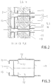
- a chamber 3 made of insulating material is fixed on a side wall 1 of a drive housing 2 and extends in the vertical direction and accommodates a circuit breaker 4, in particular a vacuum interrupter with a vertical axis.
- the circuit breaker 4 has a lower and an upper connection piece 5 and 6, from which connection tabs 7 reach outwards through a chamber front wall 8 facing away from the side wall 1 for connection to external current conductors.
- the circuit breaker 4 is located in a switch room 9 and is fixed there to brackets 10.
- the chamber 3 has a chamber rear wall 11 which runs parallel to and at a distance from the adjacent side wall 1 of the drive housing 2.
- the chamber front wall 8 and the chamber rear wall 11 are part of a one-piece profile strand of constant cross-section, the profile strand also comprising the chamber side walls 12 standing vertically on the side wall 1, so that the switch space 9 is closed in the circumferential direction of the cross-sectional profile.
- Retaining strips 13 are provided for fastening the connecting pieces 5, 6 and are drawn into the switch space 9 at opposite points from the chamber side walls 12 at a distance from the chamber rear wall 11.
- These retaining strips 13, like all other wall sections of the profile strand extend over its entire axial length.
- the connectors have as Counter holding means fastening tabs 14, which are applied to the holding strips 13 from the rear side wall 11.
- the fastening tabs 14 can then be fixed to the holding strips 13, for example by means of screw connections.
- front-side fastening tabs 14 are also provided on the respective connector 5.6.
- the fastening tabs in the switch compartment 9 rest against the inside of the chamber front wall 8, bores also being provided as holding means 10 for fastening to the chamber front wall 8.
- the fastening tabs 14 lie on the surfaces of the retaining strips 13 or the chamber front wall 8 facing the rear wall 11 of the chamber, so that, due to the distance between the holding strips 13 and the rear chamber wall 11 required for insulation purposes, the fastening tabs 14 are at a sufficient distance from their surfaces serving for fastening can be inserted axially into the switch compartment 9. Slight inclinations of the connecting pieces cannot result in the insertion movement being blocked. Dimensional tolerances also do not impede the free assembly of the circuit breaker with its connecting pieces 5, 6.
- the chamber side walls 12 are withdrawn at their ends facing the side wall 1 via the rear side wall 11, their ends being designed as angled tab strips 15.
- the tab strips 15 can be fixed to the side wall 1 by means of screws or the like.
- the front ends 16 of the chamber side walls project forward beyond the chamber front wall 8 and thus increase the dielectric strength of the chamber with respect to adjacent other pole parts in adjacent chambers 3 or other earthed parts.
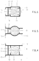
- the chamber side walls 12 are offset inwards on their section facing the side wall 1 from the rear holding strips 13, so that an additional stiffening of the profile strand in the region of the rear holding strips 13 is achieved.
- the front ends 16 are also indented.
- the chamber is accordingly pulled outward or bulged out, the bulge according to FIG. 5 being designed in an arc-shaped manner in contrast to the other flat surface designs.
- retaining strips 13 are also integrated into the profile as a counterbearing for the fastening tabs 14 in the region of the chamber front wall 8.
- These front holding strips 13 are inclined with respect to the chamber front wall 8, but they can also be arranged at a distance parallel to it, similar to the rear holding strips 13. Due to the inclination of the holding strips, it is possible to get by with a central opening provided in the chamber front wall 8 for the introduction of an assembly tool.
- This opening 17 can also be used to introduce screw connections to the holding strips facing the chamber rear wall 11.
- the central opening 17 has the advantage that the uninterrupted laterally lying sections of the chamber front wall increase the insulation distance to neighboring components. If necessary, the protruding ends can then be omitted, as shown for example in FIG. 2.
- the rear holding strips 13 are expediently inclined towards the rear wall 11 of the chamber so that the axes of bores 10 introduced as holders point towards the opening 17.
- a chamber for receiving a circuit breaker from a correspondingly shaped profile strand can be produced in a simple manner from piece goods and can therefore be adapted to different length dimensions of the circuit breaker. It is integral and closed in the circumferential direction, the chamber rear wall ensuring the necessary insulation between the active parts of the switch pole and the earth potential of the drive box 2. It is but it is also easily possible for the conductive parts of different potentials to face each other in such a way that an air gap of at least 10 mm, the insulating chamber rear wall 11 and a further air gap of at least 10 mm are alternately connected in series. The clearances are determined on the one hand by the distances between the angled ends 15 and, on the other hand, the rear holding strips 13 from the chamber rear wall 11.
Landscapes
- Breakers (AREA)
- Switch Cases, Indication, And Locking (AREA)
- Non-Silver Salt Photosensitive Materials And Non-Silver Salt Photography (AREA)
Claims (10)
- Interrupteur d'isolateur support avec un carter d'entraînement (2) et au moins une chambre (3) en matière isolante, laquelle est fixée contre une paroi latérale verticale (1) du carter d'entraînement (2) et comprend une boîte d'interrupteurs où, sur la face tournée vers le carter d'entraînement (2), sont prévues des fixations (10) pour un interrupteur de puissance (4), disposé dans la boîte d'interrupteurs (9), en particulier une chambre de commutation à vide, et à travers la face frontale duquel sont guidées, vers l'extérieur, des pièces de connexion (5, 6) pour l'interrupteur de puissance (4) tandis que la paroi arrière (11) de la chambre s'étend parallèlement et à distance de la paroi latérale voisine (1) du carter d'entraînement (2), ainsi qu'avec un appui isolé rigide sur la face avant entre les pièces de connexion (5, 6), caractérisé en ce que la chambre (3) se compose d'un profilé en continu fermé dans le sens périphérique d'une seule pièce et s'étendant dans le sens axial de l'interrupteur de puissance (4) et dont la coupe transversale est constante, auquel cas les fixations arrière (10) pour les pièces de connexion (5, 6) sont constituées au niveau de pattes de retenue (13) se dégageant depuis les parois latérales (12) de la chambre tandis que pour le soutien des pièces de connexion (5, 6) sur la face frontale, il est prévu des fixations (10) sur la paroi avant (8) de la face frontale de la chambre ou sur les pattes de retenue voisines (13).
- Interrupteur d'isolateur support selon la revendication 1, caractérisé en ce que les parois latérales (12) de la chambre sont retirées au-dessus de la paroi arrière (11) et présentent, à leurs extrémités, des pattes (15) saillantes coudées qui sont fixées à la paroi latérale (1) du carter d'entraînement (2).
- Interrupteur d'isolateur support selon la revendication 1 ou 2, caractérisé en ce que les extrémités frontales (16) des parois latérales (12) de la chambre sont avancees au-dessus du plan de la paroi avant (8) de la chambre sur la face frontale.
- Interrupteur d'isolateur support selon la revendication 1 ou l'une des suivantes, caractérisé en ce que les pièces de connexion (5, 6) présentent des languettes de fixation (14) qui sont appliquées à partir de la paroi arrière de la chambre contre les pattes de retenue (13) voisines resp. contre la surface interne de la paroi avant (8) de la chambre.
- Interrupteur d'isolateur support selon la revendication 1, 2 ou 3, caractérisé en ce que les pièces de connexion (5, 6) présentent des languettes de fixation (14) qui sont appliquées du même côté contre les pattes de retenue (13) voisines de la paroi arrière (11) resp. de la paroi avant (8) de la chambre.
- Interrupteur d'isolateur support selon la revendication 5, caractérisé en ce que les pattes de retenue (13) sont inclinées vers la paroi arrière (11) de la chambre.
- Interrupteur d'isolateur support selon la revendication 1, ou l'une des suivantes, caractérisé en ce que les fixations (10) associées à l'un des côtés des pièces de connexion (5, 6) sont alignées en coupant la paroi avant (8) de la chambre.
- Interrupteur d'isolateur support selon la revendication 5, caractérisé en ce que toutes les fixations (10) sont alignées avec une ouverture (17) disposée au centre de la paroi avant (8) de la chambre.
- Interrupteur d'isolateur support selon la revendication 1, ou l'une des suivantes, caractérisé en ce qu'au moins les extrémités tournées vers la paroi latérale (1) du carter d'entraînement (2) sont étagées vers l'intérieur à partir des pattes de fixation (13) voisines.
- Interrupteur d'isolateur support selon la revendication 1 ou l'une des suivantes, caractérisé en ce que les parois latérales (12) de la chambre sont bombées vers l'extérieur dans la zone de l'interrupteur de puissance (4).
Applications Claiming Priority (2)
| Application Number | Priority Date | Filing Date | Title |
|---|---|---|---|
| DE4010843A DE4010843A1 (de) | 1990-04-04 | 1990-04-04 | Stuetzerschalter |
| DE4010843 | 1990-04-04 |
Publications (3)
| Publication Number | Publication Date |
|---|---|
| EP0450397A2 EP0450397A2 (fr) | 1991-10-09 |
| EP0450397A3 EP0450397A3 (en) | 1991-11-21 |
| EP0450397B1 true EP0450397B1 (fr) | 1994-12-28 |
Family
ID=6403732
Family Applications (1)
| Application Number | Title | Priority Date | Filing Date |
|---|---|---|---|
| EP91104289A Expired - Lifetime EP0450397B1 (fr) | 1990-04-04 | 1991-03-20 | Dispositif d'écran pour sectionneur de puissance |
Country Status (6)
| Country | Link |
|---|---|
| US (1) | US5191516A (fr) |
| EP (1) | EP0450397B1 (fr) |
| JP (1) | JPH04223013A (fr) |
| DE (2) | DE4010843A1 (fr) |
| FI (1) | FI100492B (fr) |
| NO (1) | NO179307C (fr) |
Families Citing this family (6)
| Publication number | Priority date | Publication date | Assignee | Title |
|---|---|---|---|---|
| DE9213143U1 (de) * | 1992-09-25 | 1993-03-25 | Siemens AG, 8000 München | Vakuumschütz mit einer Anschlußvorrichtung |
| DE4419380C1 (de) * | 1994-05-30 | 1995-10-19 | Siemens Ag | Leistungsschaltermodul |
| FR2807204B1 (fr) * | 2000-03-31 | 2002-05-24 | Schneider Electric Ind Sa | Appareillage electrique de coupure multipolaire muni d'un mecanisme d'entrainement et de modules de coupure |
| US6373358B1 (en) * | 2000-05-09 | 2002-04-16 | Eaton Corporation | Power circuit breaker having molded insulative casing with a dead front |
| US6326872B1 (en) * | 2000-05-09 | 2001-12-04 | Eaton Corporation | Power circuit breaker with air gap between molded insulative casing and grounded barrier insulating operating mechanism |
| CN102420071A (zh) * | 2011-08-22 | 2012-04-18 | 宁波耀华电气科技有限责任公司 | 全封闭固封极柱 |
Family Cites Families (4)
| Publication number | Priority date | Publication date | Assignee | Title |
|---|---|---|---|---|
| DE2322372C3 (de) * | 1973-04-30 | 1980-06-04 | Siemens Ag, 1000 Berlin Und 8000 Muenchen | Mehrpoliges Vakuumschaltgerät mit isolierstoffgekapselten Schaltgefäßen |
| DE8028797U1 (de) * | 1980-10-29 | 1981-02-19 | Calor-Emag Elektrizitaets-Aktiengesellschaft, 4030 Ratingen | Vakuumschalter |
| US4536822A (en) * | 1984-04-25 | 1985-08-20 | Kearney-National, Inc. | Electric circuit interrupter and associated mounting |
| ATE95629T1 (de) * | 1988-06-14 | 1993-10-15 | Sprecher Energie Ag | Vakuumschalteranordnung. |
-
1990
- 1990-04-04 DE DE4010843A patent/DE4010843A1/de not_active Withdrawn
-
1991
- 1991-03-20 EP EP91104289A patent/EP0450397B1/fr not_active Expired - Lifetime
- 1991-03-20 DE DE59104012T patent/DE59104012D1/de not_active Expired - Fee Related
- 1991-03-22 NO NO911170A patent/NO179307C/no unknown
- 1991-03-22 US US07/673,480 patent/US5191516A/en not_active Expired - Fee Related
- 1991-04-03 JP JP3070820A patent/JPH04223013A/ja active Pending
- 1991-04-03 FI FI911599A patent/FI100492B/fi active IP Right Grant
Also Published As
| Publication number | Publication date |
|---|---|
| FI911599A0 (fi) | 1991-04-03 |
| EP0450397A2 (fr) | 1991-10-09 |
| EP0450397A3 (en) | 1991-11-21 |
| NO179307B (no) | 1996-06-03 |
| NO911170L (no) | 1991-10-07 |
| FI100492B (fi) | 1997-12-15 |
| US5191516A (en) | 1993-03-02 |
| NO179307C (no) | 1996-09-11 |
| DE4010843A1 (de) | 1991-10-10 |
| FI911599L (fi) | 1991-10-05 |
| NO911170D0 (no) | 1991-03-22 |
| DE59104012D1 (de) | 1995-02-09 |
| JPH04223013A (ja) | 1992-08-12 |
Similar Documents
| Publication | Publication Date | Title |
|---|---|---|
| EP0198099B2 (fr) | Contacteur en particulier contacteur auxiliaire ou contacteur de moteur | |
| DE202014011449U1 (de) | Halterahmen für einen Steckverbinder | |
| DE3807645A1 (de) | Steckverbindungssystem fuer elektrische leiter | |
| DE60008431T2 (de) | Lichtbogenkammer für niederspannungs-leistungsschalter | |
| WO2017182033A1 (fr) | Agencement permettant la connexion sans risque de contact d'un système de rails collecteurs de courant | |
| DD292105A5 (de) | Schaltvorrichtung mit geschuetzten unterbrechern | |
| DE69104776T2 (de) | Raummodul für ein metallgekapseltes modulares Mittelspannungsverteilersystem und ein Verteilersystem mit solchen Raummodulen. | |
| EP0450397B1 (fr) | Dispositif d'écran pour sectionneur de puissance | |
| EP0668637A1 (fr) | Bloc multiprises | |
| EP0109569B1 (fr) | Tiroir pour armoire destinée à des systèmes électriques | |
| DE3543885C1 (en) | Switch unit, especially for motor vehicles | |
| DE2802554B1 (de) | Niederspannungs-Leistungsschalter mit durch Trennwaende unterteiltem Isolierstoffgehaeuse | |
| EP0976310B1 (fr) | Appareil electrique a deux capots de boitier identiques | |
| DE4444554C2 (de) | Gekapselte elektrische Hochspannungsleitung | |
| EP0071156A2 (fr) | Bloc de rails de connexion | |
| DE9213143U1 (de) | Vakuumschütz mit einer Anschlußvorrichtung | |
| DE2629107A1 (de) | Gehaeuse zur aufnahme von gedruckten leiterplatten | |
| DE3243079A1 (de) | Schaltschrank | |
| EP1356548A1 (fr) | Dispositif de contact pour la liaison liberable d'un bloc d'assemblage mobile avec des rails conducteurs fixes | |
| DE29505243U1 (de) | Erdungsvorrichtung für einen Einschub eines Energieverteilerschrankes | |
| EP0718942B1 (fr) | Installation à haute tension | |
| DE2304639B2 (de) | Fassungsanordnung für elektrische Steckerkupplungen | |
| DE3440008A1 (de) | Paketierte sammelschiene | |
| DE3413533A1 (de) | Elektrotechnisches geraet, insbesondere fuer die nachrichtentechnik | |
| DE8700153U1 (de) | Sammelschienenblock |
Legal Events
| Date | Code | Title | Description |
|---|---|---|---|
| PUAI | Public reference made under article 153(3) epc to a published international application that has entered the european phase |
Free format text: ORIGINAL CODE: 0009012 |
|
| PUAL | Search report despatched |
Free format text: ORIGINAL CODE: 0009013 |
|
| AK | Designated contracting states |
Kind code of ref document: A2 Designated state(s): CH DE FR GB IT LI NL SE |
|
| RHK1 | Main classification (correction) |
Ipc: H01H 33/66 |
|
| AK | Designated contracting states |
Kind code of ref document: A3 Designated state(s): CH DE FR GB IT LI NL SE |
|
| 17P | Request for examination filed |
Effective date: 19920414 |
|
| RAP1 | Party data changed (applicant data changed or rights of an application transferred) |
Owner name: AEG SACHSENWERK GMBH |
|
| 17Q | First examination report despatched |
Effective date: 19940328 |
|
| GRAA | (expected) grant |
Free format text: ORIGINAL CODE: 0009210 |
|
| AK | Designated contracting states |
Kind code of ref document: B1 Designated state(s): CH DE FR GB IT LI NL SE |
|
| EAL | Se: european patent in force in sweden |
Ref document number: 91104289.3 |
|
| REF | Corresponds to: |
Ref document number: 59104012 Country of ref document: DE Date of ref document: 19950209 |
|
| ET | Fr: translation filed | ||
| ITF | It: translation for a ep patent filed | ||
| GBT | Gb: translation of ep patent filed (gb section 77(6)(a)/1977) |
Effective date: 19950301 |
|
| PLBE | No opposition filed within time limit |
Free format text: ORIGINAL CODE: 0009261 |
|
| STAA | Information on the status of an ep patent application or granted ep patent |
Free format text: STATUS: NO OPPOSITION FILED WITHIN TIME LIMIT |
|
| 26N | No opposition filed | ||
| PGFP | Annual fee paid to national office [announced via postgrant information from national office to epo] |
Ref country code: CH Payment date: 19980325 Year of fee payment: 8 |
|
| PGFP | Annual fee paid to national office [announced via postgrant information from national office to epo] |
Ref country code: GB Payment date: 19990226 Year of fee payment: 9 |
|
| PGFP | Annual fee paid to national office [announced via postgrant information from national office to epo] |
Ref country code: FR Payment date: 19990318 Year of fee payment: 9 |
|
| PGFP | Annual fee paid to national office [announced via postgrant information from national office to epo] |
Ref country code: SE Payment date: 19990322 Year of fee payment: 9 Ref country code: NL Payment date: 19990322 Year of fee payment: 9 |
|
| PG25 | Lapsed in a contracting state [announced via postgrant information from national office to epo] |
Ref country code: LI Free format text: LAPSE BECAUSE OF NON-PAYMENT OF DUE FEES Effective date: 19990331 Ref country code: CH Free format text: LAPSE BECAUSE OF NON-PAYMENT OF DUE FEES Effective date: 19990331 |
|
| REG | Reference to a national code |
Ref country code: CH Ref legal event code: PL |
|
| PG25 | Lapsed in a contracting state [announced via postgrant information from national office to epo] |
Ref country code: GB Free format text: LAPSE BECAUSE OF NON-PAYMENT OF DUE FEES Effective date: 20000320 |
|
| PG25 | Lapsed in a contracting state [announced via postgrant information from national office to epo] |
Ref country code: SE Free format text: LAPSE BECAUSE OF NON-PAYMENT OF DUE FEES Effective date: 20000321 |
|
| PG25 | Lapsed in a contracting state [announced via postgrant information from national office to epo] |
Ref country code: NL Free format text: LAPSE BECAUSE OF NON-PAYMENT OF DUE FEES Effective date: 20001001 |
|
| EUG | Se: european patent has lapsed |
Ref document number: 91104289.3 |
|
| GBPC | Gb: european patent ceased through non-payment of renewal fee |
Effective date: 20000320 |
|
| PG25 | Lapsed in a contracting state [announced via postgrant information from national office to epo] |
Ref country code: FR Free format text: LAPSE BECAUSE OF NON-PAYMENT OF DUE FEES Effective date: 20001130 |
|
| NLV4 | Nl: lapsed or anulled due to non-payment of the annual fee |
Effective date: 20001001 |
|
| REG | Reference to a national code |
Ref country code: FR Ref legal event code: ST |
|
| PG25 | Lapsed in a contracting state [announced via postgrant information from national office to epo] |
Ref country code: IT Free format text: LAPSE BECAUSE OF NON-PAYMENT OF DUE FEES;WARNING: LAPSES OF ITALIAN PATENTS WITH EFFECTIVE DATE BEFORE 2007 MAY HAVE OCCURRED AT ANY TIME BEFORE 2007. THE CORRECT EFFECTIVE DATE MAY BE DIFFERENT FROM THE ONE RECORDED. Effective date: 20050320 |
|
| PGFP | Annual fee paid to national office [announced via postgrant information from national office to epo] |
Ref country code: DE Payment date: 20060518 Year of fee payment: 16 |
|
| PG25 | Lapsed in a contracting state [announced via postgrant information from national office to epo] |
Ref country code: DE Free format text: LAPSE BECAUSE OF NON-PAYMENT OF DUE FEES Effective date: 20071002 |