EP0450397B1 - Shielding for power circuit breaker - Google Patents
Shielding for power circuit breaker Download PDFInfo
- Publication number
- EP0450397B1 EP0450397B1 EP91104289A EP91104289A EP0450397B1 EP 0450397 B1 EP0450397 B1 EP 0450397B1 EP 91104289 A EP91104289 A EP 91104289A EP 91104289 A EP91104289 A EP 91104289A EP 0450397 B1 EP0450397 B1 EP 0450397B1
- Authority
- EP
- European Patent Office
- Prior art keywords
- chamber
- wall
- switch according
- circuit breaker
- drive housing
- Prior art date
- Legal status (The legal status is an assumption and is not a legal conclusion. Google has not performed a legal analysis and makes no representation as to the accuracy of the status listed.)
- Expired - Lifetime
Links
- 239000011810 insulating material Substances 0.000 claims description 4
- 239000012212 insulator Substances 0.000 claims 10
- 238000009413 insulation Methods 0.000 description 7
- 238000010276 construction Methods 0.000 description 2
- 238000004519 manufacturing process Methods 0.000 description 2
- 238000005192 partition Methods 0.000 description 2
- 230000002411 adverse Effects 0.000 description 1
- 230000004323 axial length Effects 0.000 description 1
- 239000004020 conductor Substances 0.000 description 1
- 238000001816 cooling Methods 0.000 description 1
- 238000003780 insertion Methods 0.000 description 1
- 230000037431 insertion Effects 0.000 description 1
- 238000000034 method Methods 0.000 description 1
- 239000000047 product Substances 0.000 description 1
- 239000011265 semifinished product Substances 0.000 description 1
Images

Classifications
-
- H—ELECTRICITY
- H01—ELECTRIC ELEMENTS
- H01H—ELECTRIC SWITCHES; RELAYS; SELECTORS; EMERGENCY PROTECTIVE DEVICES
- H01H33/00—High-tension or heavy-current switches with arc-extinguishing or arc-preventing means
- H01H33/60—Switches wherein the means for extinguishing or preventing the arc do not include separate means for obtaining or increasing flow of arc-extinguishing fluid
- H01H33/66—Vacuum switches
- H01H33/666—Operating arrangements
-
- H—ELECTRICITY
- H01—ELECTRIC ELEMENTS
- H01H—ELECTRIC SWITCHES; RELAYS; SELECTORS; EMERGENCY PROTECTIVE DEVICES
- H01H9/00—Details of switching devices, not covered by groups H01H1/00 - H01H7/00
- H01H9/52—Cooling of switch parts
- H01H2009/526—Cooling of switch parts of the high voltage switches
-
- H—ELECTRICITY
- H01—ELECTRIC ELEMENTS
- H01H—ELECTRIC SWITCHES; RELAYS; SELECTORS; EMERGENCY PROTECTIVE DEVICES
- H01H33/00—High-tension or heavy-current switches with arc-extinguishing or arc-preventing means
- H01H33/60—Switches wherein the means for extinguishing or preventing the arc do not include separate means for obtaining or increasing flow of arc-extinguishing fluid
- H01H33/66—Vacuum switches
- H01H33/666—Operating arrangements
- H01H2033/6665—Details concerning the mounting or supporting of the individual vacuum bottles
Definitions
- the invention relates to a support switch according to the preamble of the first claim (see e.g. DE-U-8028797).
- the chamber has a holding wall which is spaced apart from its rear wall and which is fixed to the drive housing.
- a drive linkage for transmitting a switching movement from a drive in the switch housing to a switching lever provided on the circuit breaker is located between the holding wall and the rear wall of the chamber.
- the circuit breaker which is designed as a vacuum interrupter, has connection pieces at the top and bottom which are fastened on supports connected to the rear wall.
- the connectors are also supported on the front by a rigid insulating rod.
- the chamber also has integral upper and lower end walls connected to the other side walls, in which openings are provided for ensuring a convective cooling air flow for the circuit breaker.
- the bowl-shaped structure with the special rear space for the passage of a switching rod makes it necessary to manufacture the chambers individually in tools with mold cores which are to be pulled perpendicular to one another, and in addition an independent cover has to be provided in order to achieve a surrounding insulation. Do that between the rest Chamber existing column is not a continuous insulation.
- the front support rod between the connectors to the lid takes up additional space.
- the invention has for its object to take measures in a support switch according to the preamble of the first claim, through which a simplified manufacture of the chamber is possible with a compact design.
- the chamber can be manufactured from a semi-finished profile product, which is manufactured in a continuous drawing process, for example from a fiber-reinforced duomer by the meter. From this profile semi-finished product only a piece needs to be cut off according to the required chamber length.
- the semi-finished profile contains the necessary holding means in the form of holding strips that run in the longitudinal direction and are provided at least in the area of the rear wall of the chamber.
- the front-side holding means can be formed either by the front wall of the chamber which is integrally connected to the other jacket walls of the chamber or by further moving holding strips provided in the area thereof.
- the connecting pieces can then be fixed directly on these mounting means, so that a compact construction is possible.
- the chamber is designed to be gap-free in the circumferential direction and only needs to have openings there on the front side insofar as they are required for holding or leading out the connecting pieces.
- the chamber formed in this way also has a high mechanical strength and very good insulation properties.
- the chamber side walls can the level of the front chamber front wall must be brought forward so that the partition function is achieved in the area of the bare connections projecting outwards.
- These advanced ribs also run in the longitudinal direction with the drawn profile and can therefore be formed in one piece.
- the chamber side walls can also be pulled back over the rear side wall and provided at their ends with angled tab strips that can be attached to the side wall of the drive housing.
- the distance between the tab strips or the rear holding strips from the rear wall of the chamber is dimensioned in accordance with the required dielectric strengths of the insulation sections.
- fastening tabs on the connecting pieces which are applied from the rear wall of the chamber to the adjacent holding strips or to the front wall of the chamber.
- the circuit breaker with the connectors attached to it can thus be inserted in the longitudinal direction of the chamber profile so that the rear fastening tabs engage in the space between the holding strip arranged there and the chamber rear wall, there being sufficient free space for the fastening tabs towards the rear wall. A corresponding amount of space is then also available between the fastening tabs on the front and the brackets provided there.
- the circuit breakers provided with the connecting pieces can thus be conveniently inserted into the chamber cavity and then placed on the brackets concerned.
- the connectors can not jam or tilt between the brackets.
- openings can be provided in the front wall of the chamber through which tools can be guided up to the holders at the rear.
- the front openings can also represent brackets.
- a chamber 3 made of insulating material is fixed on a side wall 1 of a drive housing 2 and extends in the vertical direction and accommodates a circuit breaker 4, in particular a vacuum interrupter with a vertical axis.
- the circuit breaker 4 has a lower and an upper connection piece 5 and 6, from which connection tabs 7 reach outwards through a chamber front wall 8 facing away from the side wall 1 for connection to external current conductors.
- the circuit breaker 4 is located in a switch room 9 and is fixed there to brackets 10.
- the chamber 3 has a chamber rear wall 11 which runs parallel to and at a distance from the adjacent side wall 1 of the drive housing 2.
- the chamber front wall 8 and the chamber rear wall 11 are part of a one-piece profile strand of constant cross-section, the profile strand also comprising the chamber side walls 12 standing vertically on the side wall 1, so that the switch space 9 is closed in the circumferential direction of the cross-sectional profile.
- Retaining strips 13 are provided for fastening the connecting pieces 5, 6 and are drawn into the switch space 9 at opposite points from the chamber side walls 12 at a distance from the chamber rear wall 11.
- These retaining strips 13, like all other wall sections of the profile strand extend over its entire axial length.
- the connectors have as Counter holding means fastening tabs 14, which are applied to the holding strips 13 from the rear side wall 11.
- the fastening tabs 14 can then be fixed to the holding strips 13, for example by means of screw connections.
- front-side fastening tabs 14 are also provided on the respective connector 5.6.
- the fastening tabs in the switch compartment 9 rest against the inside of the chamber front wall 8, bores also being provided as holding means 10 for fastening to the chamber front wall 8.
- the fastening tabs 14 lie on the surfaces of the retaining strips 13 or the chamber front wall 8 facing the rear wall 11 of the chamber, so that, due to the distance between the holding strips 13 and the rear chamber wall 11 required for insulation purposes, the fastening tabs 14 are at a sufficient distance from their surfaces serving for fastening can be inserted axially into the switch compartment 9. Slight inclinations of the connecting pieces cannot result in the insertion movement being blocked. Dimensional tolerances also do not impede the free assembly of the circuit breaker with its connecting pieces 5, 6.
- the chamber side walls 12 are withdrawn at their ends facing the side wall 1 via the rear side wall 11, their ends being designed as angled tab strips 15.
- the tab strips 15 can be fixed to the side wall 1 by means of screws or the like.
- the front ends 16 of the chamber side walls project forward beyond the chamber front wall 8 and thus increase the dielectric strength of the chamber with respect to adjacent other pole parts in adjacent chambers 3 or other earthed parts.
- the chamber side walls 12 are offset inwards on their section facing the side wall 1 from the rear holding strips 13, so that an additional stiffening of the profile strand in the region of the rear holding strips 13 is achieved.
- the front ends 16 are also indented.
- the chamber is accordingly pulled outward or bulged out, the bulge according to FIG. 5 being designed in an arc-shaped manner in contrast to the other flat surface designs.
- retaining strips 13 are also integrated into the profile as a counterbearing for the fastening tabs 14 in the region of the chamber front wall 8.
- These front holding strips 13 are inclined with respect to the chamber front wall 8, but they can also be arranged at a distance parallel to it, similar to the rear holding strips 13. Due to the inclination of the holding strips, it is possible to get by with a central opening provided in the chamber front wall 8 for the introduction of an assembly tool.
- This opening 17 can also be used to introduce screw connections to the holding strips facing the chamber rear wall 11.
- the central opening 17 has the advantage that the uninterrupted laterally lying sections of the chamber front wall increase the insulation distance to neighboring components. If necessary, the protruding ends can then be omitted, as shown for example in FIG. 2.
- the rear holding strips 13 are expediently inclined towards the rear wall 11 of the chamber so that the axes of bores 10 introduced as holders point towards the opening 17.
- a chamber for receiving a circuit breaker from a correspondingly shaped profile strand can be produced in a simple manner from piece goods and can therefore be adapted to different length dimensions of the circuit breaker. It is integral and closed in the circumferential direction, the chamber rear wall ensuring the necessary insulation between the active parts of the switch pole and the earth potential of the drive box 2. It is but it is also easily possible for the conductive parts of different potentials to face each other in such a way that an air gap of at least 10 mm, the insulating chamber rear wall 11 and a further air gap of at least 10 mm are alternately connected in series. The clearances are determined on the one hand by the distances between the angled ends 15 and, on the other hand, the rear holding strips 13 from the chamber rear wall 11.
Landscapes
- Breakers (AREA)
- Switch Cases, Indication, And Locking (AREA)
- Non-Silver Salt Photosensitive Materials And Non-Silver Salt Photography (AREA)
Description
Die Erfindung betrifft einen Stützerschalter gemäß dem Oberbegriff des ersten Anspruchs (siehe z.B. DE-U-8028797 ).The invention relates to a support switch according to the preamble of the first claim (see e.g. DE-U-8028797).
Es ist bei Stützerschaltern bekannt, an einer senkrechten Seitenwand eines Antriebsgehäuses eine aus Isolierstoff bestehende Kammer vorzusehen, die einen Schalterraum mit darin angeorndetem Leistungsschalter aufweist. Die Kammer weist eine von ihrer Rückwand beabstandete Haltewand, welche am Antriebsgehäuse festgesetzt ist. Zwischen der Haltewand und der Kammerückwand befindet sich ein Antriebsgestänge für die Übertragung einer Schaltbewegung von einem Antrieb im Schaltgehäuse auf einen am Leistungsschalter vorgesehenen Schalthebel. Der als Vakuumschaltkammer ausgebildete Leistungsschalter weist oben und unten Anschlußstücke auf, die auf mit der Rückwand verbundenen Stützen befestigt sind. Die Anschlußstücke sind zusätzlich frontseitig durch eine starre Isolierstange gegeneinander abgestützt. Von den Anschlußstücken greifen elektrische Anschlußarme durch einen auf die Frontseite der Kammer aufgesetzten Deckel aus Isolierstoff. Die Kammer besitzt zudem einstückig mit den übrigen Seitenwänden verbundene obere und untere Abschlußwände, in welchen Durchbrechungen für die Sicherstellung einer konvektiven Kühlluftströmung für den Leistungsschalter vorgesehen sind. Der schalenförmige Aufbau mit dem besonderen rückwärtigen Raum für die Durchführung einer Schaltstange macht die Einzelherstellung der Kammern in Werkzeugen mit senkrecht zueinander zu ziehenden Formkernen erforderlich, wobei zusätzlich ein eigenständiger Deckel bereitzustellen ist, um eine umschließende Isolierung zu erzielen. Dabei stellen die zwischen der übrigen Kammer vorhandenen Spalte keine durchgehende Isolierung dar. Zudem beansprucht die frontseitige Stützstange zwischen den Anschlußstücken zum Deckel hin zusätzlichen Raum.It is known in the case of support switches to provide a chamber made of insulating material on a vertical side wall of a drive housing and having a switch space with a circuit breaker arranged therein. The chamber has a holding wall which is spaced apart from its rear wall and which is fixed to the drive housing. A drive linkage for transmitting a switching movement from a drive in the switch housing to a switching lever provided on the circuit breaker is located between the holding wall and the rear wall of the chamber. The circuit breaker, which is designed as a vacuum interrupter, has connection pieces at the top and bottom which are fastened on supports connected to the rear wall. The connectors are also supported on the front by a rigid insulating rod. Electrical connecting arms reach from the connecting pieces through a cover made of insulating material placed on the front of the chamber. The chamber also has integral upper and lower end walls connected to the other side walls, in which openings are provided for ensuring a convective cooling air flow for the circuit breaker. The bowl-shaped structure with the special rear space for the passage of a switching rod makes it necessary to manufacture the chambers individually in tools with mold cores which are to be pulled perpendicular to one another, and in addition an independent cover has to be provided in order to achieve a surrounding insulation. Do that between the rest Chamber existing column is not a continuous insulation. In addition, the front support rod between the connectors to the lid takes up additional space.
Der Erfindung liegt die Aufgabe zugrunde, bei einem Stützerschalter gemäß dem Oberbegriff des ersten Anspruchs Maßnahmen zu treffen, durch die eine vereinfachte Herstellung der Kammer bei gedrängter Bauweise ermöglicht wird.The invention has for its object to take measures in a support switch according to the preamble of the first claim, through which a simplified manufacture of the chamber is possible with a compact design.
Die Lösung dieser Aufgabe erfolgt gemäß der Erfindung durch die Merkmale des ersten Anspruchs.This object is achieved according to the invention by the features of the first claim.
Bei einer Ausgestaltung eines Stützerschalters gemäß der Erfindung kann die Kammer aus einem Profil-Halbzeug gefertigt werden, das im Strangziehverfahren beispielsweise aus einem faserverstärkten Duomer als Meterware gefertigt wird. Von diesem Profil-Halbzeug braucht dann lediglich ein Stück entsprechend der erforderlichen Kammerlänge abgeschnitten zu werden. Dabei enthält das Profil-Halbzeug die erforderlichen Halterungsmittel in Form von in Längsrichtung mitlaufenden Haltestreifen, die zumindest im Bereich der Kammerrückwand vorgesehen sind. Die frontseitige Halterungsmittel können dabei entweder durch die einstückig mit den übrigen Mantelwänden der Kammer verbundene Kammervorderwand oder in deren Bereich vorgesehene weitere mitlaufende Haltestreifen gebildet sein. An diesen Halterungsmitteln können dann die Anschlußstücke unmittelbar festgesetzt werden, so daß sich eine gedrängte Bauweise ermöglicht. Dabei ist die Kammer in Umfangsrichtung spaltfrei ausgebildet und braucht nur frontseitig dort Durchbrechungen auszuweisen, soweit sie für die Halterung oder Herausführung der Anschlußstücke erforderlich sind. Die so gebildete Kammer weist zudem eine hohe mechanische Festigkeit als auch sehr gute Isolationseigenschaften auf.In an embodiment of a support switch according to the invention, the chamber can be manufactured from a semi-finished profile product, which is manufactured in a continuous drawing process, for example from a fiber-reinforced duomer by the meter. From this profile semi-finished product only a piece needs to be cut off according to the required chamber length. The semi-finished profile contains the necessary holding means in the form of holding strips that run in the longitudinal direction and are provided at least in the area of the rear wall of the chamber. The front-side holding means can be formed either by the front wall of the chamber which is integrally connected to the other jacket walls of the chamber or by further moving holding strips provided in the area thereof. The connecting pieces can then be fixed directly on these mounting means, so that a compact construction is possible. The chamber is designed to be gap-free in the circumferential direction and only needs to have openings there on the front side insofar as they are required for holding or leading out the connecting pieces. The chamber formed in this way also has a high mechanical strength and very good insulation properties.
Zur Verbesserung der Spannungsfestigkeit gegenüber benachbarten weiteren Kammern oder anderen geerdeten Teilen können die Kammerseitenwände über die Ebene der frontseitigen Kammervorderwand vorgezogen sein, so daß im Bereich der nach vorn heraus stehenden blanken Anschlüsse Trennwandfunktion erreicht ist. Diese vorgezogenen Rippen laufen ebenfalls in Längsrichtung mit dem gezogenen Profil mit und können daher einstückig angeformt werden. Auch können die Kammerseitenwände über die Rückseitenwand zurückgezogen und an ihren Enden mit winklig abstehenden Laschenstreifen versehen werden, die an der Seitenwand des Antriebsgehäuses festgesetzt werden können. Der Abstand der Laschenstreifen bzw. der rückwärtigen Haltestreifen von der Kammerrückseitenwand ist dabei gemäß den geforderten Spannungsfestigkeiten der Isolationsstrecken bemessen. An den Anschlußstücken befinden sich zudem Befestigungslaschen, die von der Kammerrückwand aus an die benachbarten Haltestreifen bzw. an die Kammervorderwand angelegt sind. Der Leistungsschalter mit den daran befestigten Anschlußstücken kann somit in Längsrichtung des Kammerprofils so eingeschoben werden, daß die rückwärtigen Befestigungslaschen in den Raum zwischen dem dort angeordneten Haltestreifen und der Kammerrückwand eingreifen, wobei für die Befestigungslaschen zur Rückwand hin ausreichend freier Raum vorhanden ist. Entsprechend viel Platz ist dann auch zwischen den frontseitigen Befestigungslaschen und den dort vorgesehenen Halterungen vorhanden. Die mit den Anschlußstücken versehenen Leistungsschalter lassen sich so bequem in den Kammerhohlraum einschieben und anschließend an die betreffenden Halterungen anlegen. Die Anschlußstücke können sich daher nicht zwischen den Halterungen verklemmen oder verkanten. Um die Montage der Anschlußstücke von der Frontseite her zu ermöglichen, können Öffnungen in der Kammervorderwand vorgesehen sein, durch die Werkzeuge bis zu den hinten liegenden Halterungen geführt werden können. Dabei können die vorderen Öffnungen zugleich Halterungen darstellen.To improve the dielectric strength compared to other adjacent chambers or other earthed parts, the chamber side walls can the level of the front chamber front wall must be brought forward so that the partition function is achieved in the area of the bare connections projecting outwards. These advanced ribs also run in the longitudinal direction with the drawn profile and can therefore be formed in one piece. The chamber side walls can also be pulled back over the rear side wall and provided at their ends with angled tab strips that can be attached to the side wall of the drive housing. The distance between the tab strips or the rear holding strips from the rear wall of the chamber is dimensioned in accordance with the required dielectric strengths of the insulation sections. There are also fastening tabs on the connecting pieces, which are applied from the rear wall of the chamber to the adjacent holding strips or to the front wall of the chamber. The circuit breaker with the connectors attached to it can thus be inserted in the longitudinal direction of the chamber profile so that the rear fastening tabs engage in the space between the holding strip arranged there and the chamber rear wall, there being sufficient free space for the fastening tabs towards the rear wall. A corresponding amount of space is then also available between the fastening tabs on the front and the brackets provided there. The circuit breakers provided with the connecting pieces can thus be conveniently inserted into the chamber cavity and then placed on the brackets concerned. The connectors can not jam or tilt between the brackets. In order to enable the connection pieces to be installed from the front, openings can be provided in the front wall of the chamber through which tools can be guided up to the holders at the rear. The front openings can also represent brackets.
Andere vorteilhafte Ausgestaltungen der Erfindung sind in weiteren Ansprüchen angegeben.Other advantageous embodiments of the invention are specified in further claims.
Die Erfindung ist nachfolgend anhand der Zeichnungen von Ausführungsbeispielen näher erläutert.The invention is based on the drawings of Exemplary embodiments explained in more detail.
Es zeigt:
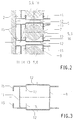
- Fig. 1 einen Stützerschalter in einem schematischen Seitenschnitt,
- Fig. 2 eine Draufsicht auf einen teilweise dargestellten Stützerschalter und
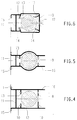
- Fig. 3 bis Fig. 6 Querschnittsdarstellungen verschiedener Kammern.
- 1 is a support switch in a schematic side section,
- Fig. 2 is a plan view of a partially shown support switch and
- 3 to 6 cross-sectional representations of different chambers.
Bei einem Stützerschalter ist an einer Seitenwand 1 eines Antriebsgehäuses 2 eine aus Isolierstoff bestehende Kammer 3 festgesetzt, die sich in senkrechter Richtung erstreckt und einen Leistungsschalter 4, insbesondere eine Vakuumschaltkammer mit senkrecher Achse aufnimmt. Der Leistungsschalter 4 besitzt ein unteres und ein oberes Anschlußstück 5 bzw. 6, von welchen Anschlußlaschen 7 durch eine der Seitenwand 1 abgewandte Kammervorderwand 8 für die Verbindung mit äußeren Stromleitern nach außen greifen. Der Leistungsschalter 4 befindet sich in einem Schalterraum 9 und ist dort an Halterungen 10 festgesetzt. Die Kammer 3 weist eine Kammerrückwand 11 auf, die parallel zu und mit Abstand von der benachbarten Seitenwand 1 des Antriebsgehäuses 2 verläuft. Die Kammervorderwand 8 und die Kammerrückseitenwand 11 sind Teil eines einstückigen Profilstranges gleichbleibenden Querschnitts, wobei der Profilstrang auch die senkrecht auf der Seitenwand 1 stehenden Kammerseitenwände 12 umfaßt, so daß der Schalterraum 9 in Umfangsrichtung des Querschnittsprofils geschlossen ist. Zur Befestigung der Anschlußstücke 5,6 sind Haltestreifen 13 vorgesehen, die von den Kammerseitenwänden 12 mit Abstand von der Kammerrückseitenwand 11 an gegenüberliegenden Stellen in den Schalterraum 9 hineingezogen sind. Diese Haltstreifen 13 erstrecken sich wie alle übrigen Wandungsabschnitte des Profilstranges über dessen gesamte axiale Länge. In den Haltestreifen befinden sich als Halterungen Bohrungen im Bereich der Anschlußstücke. Die Anschlußstücke besitzen als Gegenhaltemittel Befestigungslaschen 14, welche von der Rückseitenwand 11 aus an die Haltestreifen 13 angelegt sind. Die Befestigungslaschen 14 können dann beispielsweise mittels Schraubverbindungen an den Haltestreifen 13 festgesetzt werden. Für die gegenüberliegende, frontseitige Befestigung sind am jeweiligen Anschlußstück 5,6 ebenfalls Befestigungslaschen 14 vorgesehen.In the case of a support switch, a
Gemäß den Figuren 2 bis 5 liegen die Befestigungslaschen im Schalterraum 9 an der Innenseite der Kammervorderwand 8 an, wobei für die Befestigung an der Kammervorderwand 8 ebenfalls Bohrungen als Haltemittel 10 vorgesehen sind. Die Befestigungslaschen 14 liegen dabei auf den der Kammerrückwand 11 zugewandten Flächen der Haltestreifen 13 bzw. der Kammervorderwand 8 an, so daß aufgrund des für Isolationszwecke erforderlichen Abstandes zwischen den Haltestreifen 13 und der Kammerrückwand 11 die Befestigungslaschen 14 mit ausreichendem Abstand von ihren der Befestigung dienenden Flächen axial in den Schalterraum 9 eingeschoben werden können. Geringfügige Schrägstellungen der Anschlußstücke können dadurch nicht zu einem Blockieren der Einschubbewegung führen. Auch behindern Maßtoleranzen nicht die freie Montierbarkeit des Leistungsschalters mit seinen Anschlußstücken 5,6.According to FIGS. 2 to 5, the fastening tabs in the
Die Kammerseitenwände 12 sind an ihren der Seitenwand 1 zugewandten Enden über die Rückseitenwand 11 zurückgezogen, wobei ihre Enden als abgewinkelte Laschenstreifen 15 ausgebildet sind. Diese Laschenstreifen 15 sind wie die Haltestreifen 13 gemäß Figur 2 aufeinander zugerichtet. Sie können jedoch auch gemäß den Figuren 4,5 voneinander wegweisen, wenn ausreichender Raum zwischen benachbarten Kammern 3 vorhanden ist. Die Laschenstreifen 15 können dabei mittels Schrauben oder dergleichen an der Seitenwand 1 festgesetzt werden. Die frontseitigen Enden 16 der Kammerseitenwände stehen nach vorn über die Kammervorderwand 8 hinaus und vergrößern so die Spannungsfestigkeit der Kammer gegenüber benachbarten anderen Polteilen in daneben angeordneten Kammern 3 oder anderen geerdeten Teilen.The
Gemäß den Figuren 2, 3 und 6 sind die Kammerseitenwände 12 an ihrem der Seitenwand 1 zugewandten Abschnitt von den rückwärtigen Haltestreifen 13 ab nach innen abgesetzt, so daß eine zusätzliche Versteifung des Profilstranges im Bereich der hinteren Haltestreifen 13 erreicht wird. Dabei sind auch die frontseitigen Enden 16 nach innen eingerückt. Im Bereich des Schalterraumes 3 ist demgemäß die Kammer nach außen gezogen bzw. ausgebaucht, wobei die Ausbauchung gemäß Figur 5 im Gegensatz zu den übrigen planflächigen Ausbildungen bogenförmig gestaltet ist.According to FIGS. 2, 3 and 6, the
Gemäß Figur 6 sind als Gegenlager für die Befestigungslaschen 14 im Bereich der Kammervorderwand 8 ebenfalls Haltestreifen 13 in das Profil integriert. Diese frontseitigen Haltestreifen 13 sind gegenüber der Kammervorderwand 8 geneigt, sie können jedoch auch mit Abstand parallel dazu ähnlich den hinteren Haltestreifen 13 angeordnet sein. Durch die Neigung der Haltestreifen ist es möglich, mit einer in der Kammervorderwand 8 vorgesehenen mittigen Öffnung für die Einführung eines Montagewerkzeugs auszukommen. Diese Öffnung 17 kann dabei auch dazu benutzt werden, Schraubverbindungen an den der Kammerrückwand 11 zugewandten Haltestreifen einzubringen. Dabei hat die mittige Öffnung 17 den Vorteil, daß die nicht unterbrochenen seitlich davon liegenden Abschnitte der Kammervorderwand die Isolationsstrecke zu benachbarten Bauteilen vergrößert. Es können dann gegebenenfalls die überstehenden Enden entfallen, wie sie beispielsweise in Figur 2 dargestellt sind. Zweckmäßig sind in diesem Falle auch die rückwärtigen Haltestreifen 13 zur Kammerrückwand 11 hin so geneigt, daß die Achsen von als Halterungen eingebrachten Bohrungen 10 zur Öffnung 17 hinweisen.According to FIG. 6,
Eine Kammer für die Aufnahme eines Leistungsschalters aus einem entsprechend geformten Profilstrang läßt sich in einfacher Weise aus Meterware herstellen und kann daher an unterschiedliche Längenabmessungen des Leistungsschalters angepaßt werden. Sie ist in Umfangsrichtung einstückig und geschlossen, wobei die Kammerrückwand die notwendige Isolierung zwischen den Aktivteilen des Schalter-Poles und dem Erdpotential des Antriebskastens 2 sicherstellt. Es ist damit aber auch ohne weiteres möglich, daß sich die leitenden Teile unterschiedlichen Potentials so gegenüberstehen, daß abwechselnd eine Luftstrecke von wenigstens 10 mm, die isolierende Kammerrückwand 11 und eine weitere Luftstrecke von wenigstens 10 mm in Reihe geschaltet sind. Die Luftstrecken werden dabei durch die Abstände einerseits der abgewinkelten Enden 15 und andererseits der rückwärtigen Halteleisten 13 von der Kammerrückwand 11 bestimmt. Auf der gegenüberliegenden Seite werden durch die überstehenden Enden 16 Trennwandfunktionen erzeugt. In mechanischer Sicht ist die Befestigung der Kammer 3 am Antriebsgehäuse 2 in einfacher Weise realisierbar, während die Befestigung der Aktivteile des Pols, also des Leistungsschalters 4 innerhalb des Strangprofils realisiert ist. Durch die Anbringung von Halteleisten 13 ergibt sich dazu auch die Möglichkeit, anstelle von Schraubverbindungen Klemm- oder Formschlußverbindungen vorzusehen. Die in das Profil integrierten Halteleisten 13 bzw. die im gleichen Sinne benutzte Kammervorderwand beeinflußen die guten elektrischen Eigenschaften der Konstruktion nicht nachteilig.A chamber for receiving a circuit breaker from a correspondingly shaped profile strand can be produced in a simple manner from piece goods and can therefore be adapted to different length dimensions of the circuit breaker. It is integral and closed in the circumferential direction, the chamber rear wall ensuring the necessary insulation between the active parts of the switch pole and the earth potential of the
Claims (10)
- Insulator switch having a drive housing (2) and at least one chamber (3) consisting of insulating material, which is fixed to a vertical side wall (1) of the drive housing (2) and contains a switch chamber, in which on the side facing the drive housing (2) mounts (10) are provided for a power circuit breaker (4), in particular vacuum switch chamber, disposed in the switch chamber (9), and through the front face of which connecting members (5, 6) for the power circuit breaker (4) pass to the outside, whilst the chamber rear wall (11) extends parallel to and with clearance from the adjacent side wall (1) of the drive housing (2), as well as having a rigid, insulated support at the front between the connecting members (5, 6), characterised in that the chamber (3) consists of a one-piece profile strand of constant cross-section, which is closed in the circumferential direction and extends in the axial direction of the power circuit breaker (4), wherein the rear mounts (10) for the connecting members (5, 6) are formed on holding strips (13) extending from the chamber side walls (12), whilst mounts (10) for the front support for the connecting members (5, 6) are provided on the front chamber front wall (8) or on adjacent holding strips (13).
- Insulator switch according to claim 1, characterised in that the chamber side walls (12) are set back over the rear side wall (11) and have at their ends fishplate strips (15) projecting at an angle and fixed to the side wall (1) of the drive housing (2).
- Insulator switch according to claim 1 or 2, characterised in that the front ends (16) of the chamber side walls (12) extend forward over the plane of the front chamber front wall (8).
- Insulator switch according to claim 1 or one of the subsequent claims, characterised in that the connecting members (5, 6) have fixing plates (14), which are applied to the adjacent holding strips (13) or the inner face of the chamber front wall (8) from the chamber rear wall (11).
- Insulator switch according to claim 1, 2 or 3, characterised in that the connecting members (5, 6) have fixing plates (14) which are applied reversibly to the holding strips (13) adjacent to the chamber rear wall (11) or the chamber front wall (8).
- Insulator switch according to claim 5, characterised in that the holding strips (13) are inclined towards the chamber rear wall (11).
- Insulator switch according to claim 1 or one of the subsequent claims, characterised in that the mounts (10) associated with one side of a connecting member (5, 6) lie in a line passing through the chamber front wall (8).
- Insulator switch according to claim 6, characterised in that all the mounts (10) lie in a line with an aperture (17) disposed in the centre of the chamber front wall (8).
- Insulator switch according to claim 1 or one of the subsequent claims, characterised in that at least the ends associated with the side wall (1) of the drive housing (2) are stepped down inwardly from the adjacent holding strips (13).
- Insulator switch according to claim 1 or one of the subsequent claims, characterised in that the chamber side walls (12) are convex in the region of the power circuit breaker (4).
Applications Claiming Priority (2)
| Application Number | Priority Date | Filing Date | Title |
|---|---|---|---|
| DE4010843 | 1990-04-04 | ||
| DE4010843A DE4010843A1 (en) | 1990-04-04 | 1990-04-04 | SUPPORT SWITCH |
Publications (3)
| Publication Number | Publication Date |
|---|---|
| EP0450397A2 EP0450397A2 (en) | 1991-10-09 |
| EP0450397A3 EP0450397A3 (en) | 1991-11-21 |
| EP0450397B1 true EP0450397B1 (en) | 1994-12-28 |
Family
ID=6403732
Family Applications (1)
| Application Number | Title | Priority Date | Filing Date |
|---|---|---|---|
| EP91104289A Expired - Lifetime EP0450397B1 (en) | 1990-04-04 | 1991-03-20 | Shielding for power circuit breaker |
Country Status (6)
| Country | Link |
|---|---|
| US (1) | US5191516A (en) |
| EP (1) | EP0450397B1 (en) |
| JP (1) | JPH04223013A (en) |
| DE (2) | DE4010843A1 (en) |
| FI (1) | FI100492B (en) |
| NO (1) | NO179307C (en) |
Families Citing this family (6)
| Publication number | Priority date | Publication date | Assignee | Title |
|---|---|---|---|---|
| DE9213143U1 (en) * | 1992-09-25 | 1993-03-25 | Siemens AG, 8000 München | Vacuum contactor with a connection device |
| DE4419380C1 (en) * | 1994-05-30 | 1995-10-19 | Siemens Ag | Circuit breaker module |
| FR2807204B1 (en) * | 2000-03-31 | 2002-05-24 | Schneider Electric Ind Sa | ELECTRIC MULTIPOLAR CUTTING APPARATUS PROVIDED WITH A DRIVE MECHANISM AND CUTTING MODULES |
| US6326872B1 (en) * | 2000-05-09 | 2001-12-04 | Eaton Corporation | Power circuit breaker with air gap between molded insulative casing and grounded barrier insulating operating mechanism |
| US6373358B1 (en) * | 2000-05-09 | 2002-04-16 | Eaton Corporation | Power circuit breaker having molded insulative casing with a dead front |
| CN102420071A (en) * | 2011-08-22 | 2012-04-18 | 宁波耀华电气科技有限责任公司 | Totally-enclosed solid-sealed polar pole |
Family Cites Families (4)
| Publication number | Priority date | Publication date | Assignee | Title |
|---|---|---|---|---|
| DE2322372C3 (en) * | 1973-04-30 | 1980-06-04 | Siemens Ag, 1000 Berlin Und 8000 Muenchen | Multipole vacuum switching device with switching vessels encapsulated in insulating material |
| DE8028797U1 (en) * | 1980-10-29 | 1981-02-19 | Calor-Emag Elektrizitaets-Aktiengesellschaft, 4030 Ratingen | Vacuum switch |
| US4536822A (en) * | 1984-04-25 | 1985-08-20 | Kearney-National, Inc. | Electric circuit interrupter and associated mounting |
| DE58905809D1 (en) * | 1988-06-14 | 1993-11-11 | Sprecher En Ag Oberentfelden | Vacuum switch arrangement. |
-
1990
- 1990-04-04 DE DE4010843A patent/DE4010843A1/en not_active Withdrawn
-
1991
- 1991-03-20 DE DE59104012T patent/DE59104012D1/en not_active Expired - Fee Related
- 1991-03-20 EP EP91104289A patent/EP0450397B1/en not_active Expired - Lifetime
- 1991-03-22 NO NO911170A patent/NO179307C/en unknown
- 1991-03-22 US US07/673,480 patent/US5191516A/en not_active Expired - Fee Related
- 1991-04-03 FI FI911599A patent/FI100492B/en active IP Right Grant
- 1991-04-03 JP JP3070820A patent/JPH04223013A/en active Pending
Also Published As
| Publication number | Publication date |
|---|---|
| NO911170D0 (en) | 1991-03-22 |
| DE4010843A1 (en) | 1991-10-10 |
| FI911599A0 (en) | 1991-04-03 |
| NO911170L (en) | 1991-10-07 |
| DE59104012D1 (en) | 1995-02-09 |
| NO179307B (en) | 1996-06-03 |
| EP0450397A3 (en) | 1991-11-21 |
| FI100492B (en) | 1997-12-15 |
| US5191516A (en) | 1993-03-02 |
| NO179307C (en) | 1996-09-11 |
| EP0450397A2 (en) | 1991-10-09 |
| JPH04223013A (en) | 1992-08-12 |
| FI911599L (en) | 1991-10-05 |
Similar Documents
| Publication | Publication Date | Title |
|---|---|---|
| EP0198099B2 (en) | Contactor, particularly auxiliary or motor contactor | |
| DE202014011449U1 (en) | Holding frame for a connector | |
| DE3807645A1 (en) | CONNECTING SYSTEM FOR ELECTRICAL LADDERS | |
| DE60008431T2 (en) | ARC CHAMBER FOR LOW VOLTAGE CIRCUIT BREAKERS | |
| DD292105A5 (en) | SWITCHING DEVICE WITH PROTECTED INTERRUPTORS | |
| EP3446381A1 (en) | Assembly for the touch-proof contacting of a bus bar system | |
| DE69104776T2 (en) | Room module for a metal-encapsulated modular medium-voltage distribution system and a distribution system with such room modules. | |
| EP0450397B1 (en) | Shielding for power circuit breaker | |
| EP0668637A1 (en) | Multisocket power outlet device | |
| EP1199774B1 (en) | Electrical terminal block for side by side mounting in particular multi-level terminal block | |
| DE3543885C1 (en) | Switch unit, especially for motor vehicles | |
| DE2802554B1 (en) | Low-voltage circuit-breaker with an insulating housing divided by partitions | |
| EP0109569A2 (en) | Drawer for an electrical installation cabinet | |
| EP0976310B1 (en) | Electrical appliance with two identically built casing shells | |
| EP0071156A2 (en) | Connection rail assembly | |
| DE9213143U1 (en) | Vacuum contactor with a connection device | |
| DE2629107A1 (en) | Mounting frame for printed circuit boards - uses profile rails and horizontal shielding plates for communications appts. | |
| DE3243079A1 (en) | Switchgear cabinet | |
| EP1356548A1 (en) | Contact device for the detachable connection of a mobile appliance unit to fixed conductor rails | |
| DE29505243U1 (en) | Earthing device for a slide-in of an energy distribution cabinet | |
| EP0718942B1 (en) | High voltage installation | |
| DE2304639B2 (en) | Socket arrangement for electrical plug couplings | |
| DE3440008A1 (en) | PACKED BUSBAR | |
| DE3413533A1 (en) | Electrical apparatus, especially for telecommunications | |
| DE8700153U1 (en) | Busbar block |
Legal Events
| Date | Code | Title | Description |
|---|---|---|---|
| PUAI | Public reference made under article 153(3) epc to a published international application that has entered the european phase |
Free format text: ORIGINAL CODE: 0009012 |
|
| PUAL | Search report despatched |
Free format text: ORIGINAL CODE: 0009013 |
|
| AK | Designated contracting states |
Kind code of ref document: A2 Designated state(s): CH DE FR GB IT LI NL SE |
|
| RHK1 | Main classification (correction) |
Ipc: H01H 33/66 |
|
| AK | Designated contracting states |
Kind code of ref document: A3 Designated state(s): CH DE FR GB IT LI NL SE |
|
| 17P | Request for examination filed |
Effective date: 19920414 |
|
| RAP1 | Party data changed (applicant data changed or rights of an application transferred) |
Owner name: AEG SACHSENWERK GMBH |
|
| 17Q | First examination report despatched |
Effective date: 19940328 |
|
| GRAA | (expected) grant |
Free format text: ORIGINAL CODE: 0009210 |
|
| AK | Designated contracting states |
Kind code of ref document: B1 Designated state(s): CH DE FR GB IT LI NL SE |
|
| EAL | Se: european patent in force in sweden |
Ref document number: 91104289.3 |
|
| REF | Corresponds to: |
Ref document number: 59104012 Country of ref document: DE Date of ref document: 19950209 |
|
| ET | Fr: translation filed | ||
| ITF | It: translation for a ep patent filed | ||
| GBT | Gb: translation of ep patent filed (gb section 77(6)(a)/1977) |
Effective date: 19950301 |
|
| PLBE | No opposition filed within time limit |
Free format text: ORIGINAL CODE: 0009261 |
|
| STAA | Information on the status of an ep patent application or granted ep patent |
Free format text: STATUS: NO OPPOSITION FILED WITHIN TIME LIMIT |
|
| 26N | No opposition filed | ||
| PGFP | Annual fee paid to national office [announced via postgrant information from national office to epo] |
Ref country code: CH Payment date: 19980325 Year of fee payment: 8 |
|
| PGFP | Annual fee paid to national office [announced via postgrant information from national office to epo] |
Ref country code: GB Payment date: 19990226 Year of fee payment: 9 |
|
| PGFP | Annual fee paid to national office [announced via postgrant information from national office to epo] |
Ref country code: FR Payment date: 19990318 Year of fee payment: 9 |
|
| PGFP | Annual fee paid to national office [announced via postgrant information from national office to epo] |
Ref country code: SE Payment date: 19990322 Year of fee payment: 9 Ref country code: NL Payment date: 19990322 Year of fee payment: 9 |
|
| PG25 | Lapsed in a contracting state [announced via postgrant information from national office to epo] |
Ref country code: LI Free format text: LAPSE BECAUSE OF NON-PAYMENT OF DUE FEES Effective date: 19990331 Ref country code: CH Free format text: LAPSE BECAUSE OF NON-PAYMENT OF DUE FEES Effective date: 19990331 |
|
| REG | Reference to a national code |
Ref country code: CH Ref legal event code: PL |
|
| PG25 | Lapsed in a contracting state [announced via postgrant information from national office to epo] |
Ref country code: GB Free format text: LAPSE BECAUSE OF NON-PAYMENT OF DUE FEES Effective date: 20000320 |
|
| PG25 | Lapsed in a contracting state [announced via postgrant information from national office to epo] |
Ref country code: SE Free format text: LAPSE BECAUSE OF NON-PAYMENT OF DUE FEES Effective date: 20000321 |
|
| PG25 | Lapsed in a contracting state [announced via postgrant information from national office to epo] |
Ref country code: NL Free format text: LAPSE BECAUSE OF NON-PAYMENT OF DUE FEES Effective date: 20001001 |
|
| EUG | Se: european patent has lapsed |
Ref document number: 91104289.3 |
|
| GBPC | Gb: european patent ceased through non-payment of renewal fee |
Effective date: 20000320 |
|
| PG25 | Lapsed in a contracting state [announced via postgrant information from national office to epo] |
Ref country code: FR Free format text: LAPSE BECAUSE OF NON-PAYMENT OF DUE FEES Effective date: 20001130 |
|
| NLV4 | Nl: lapsed or anulled due to non-payment of the annual fee |
Effective date: 20001001 |
|
| REG | Reference to a national code |
Ref country code: FR Ref legal event code: ST |
|
| PG25 | Lapsed in a contracting state [announced via postgrant information from national office to epo] |
Ref country code: IT Free format text: LAPSE BECAUSE OF NON-PAYMENT OF DUE FEES;WARNING: LAPSES OF ITALIAN PATENTS WITH EFFECTIVE DATE BEFORE 2007 MAY HAVE OCCURRED AT ANY TIME BEFORE 2007. THE CORRECT EFFECTIVE DATE MAY BE DIFFERENT FROM THE ONE RECORDED. Effective date: 20050320 |
|
| PGFP | Annual fee paid to national office [announced via postgrant information from national office to epo] |
Ref country code: DE Payment date: 20060518 Year of fee payment: 16 |
|
| PG25 | Lapsed in a contracting state [announced via postgrant information from national office to epo] |
Ref country code: DE Free format text: LAPSE BECAUSE OF NON-PAYMENT OF DUE FEES Effective date: 20071002 |