EP0450160A2 - Knotenpunkt-Steuergerät mit Bedienvorrichtung für die Strassenverkehrstechnik - Google Patents
Knotenpunkt-Steuergerät mit Bedienvorrichtung für die Strassenverkehrstechnik Download PDFInfo
- Publication number
- EP0450160A2 EP0450160A2 EP90123242A EP90123242A EP0450160A2 EP 0450160 A2 EP0450160 A2 EP 0450160A2 EP 90123242 A EP90123242 A EP 90123242A EP 90123242 A EP90123242 A EP 90123242A EP 0450160 A2 EP0450160 A2 EP 0450160A2
- Authority
- EP
- European Patent Office
- Prior art keywords
- control device
- control
- operating
- operating device
- door
- Prior art date
- Legal status (The legal status is an assumption and is not a legal conclusion. Google has not performed a legal analysis and makes no representation as to the accuracy of the status listed.)
- Granted
Links
- 125000004122 cyclic group Chemical group 0.000 claims abstract description 5
- 238000010586 diagram Methods 0.000 claims description 19
- 125000002015 acyclic group Chemical group 0.000 claims description 6
- 238000000819 phase cycle Methods 0.000 claims description 5
- 239000002313 adhesive film Substances 0.000 description 2
- 206010039203 Road traffic accident Diseases 0.000 description 1
- XAGFODPZIPBFFR-UHFFFAOYSA-N aluminium Chemical compound [Al] XAGFODPZIPBFFR-UHFFFAOYSA-N 0.000 description 1
- 229910052782 aluminium Inorganic materials 0.000 description 1
- 238000009434 installation Methods 0.000 description 1
- 238000012423 maintenance Methods 0.000 description 1
- 238000004519 manufacturing process Methods 0.000 description 1
- 238000011022 operating instruction Methods 0.000 description 1
- XLYOFNOQVPJJNP-UHFFFAOYSA-N water Substances O XLYOFNOQVPJJNP-UHFFFAOYSA-N 0.000 description 1
Images

Classifications
-
- G—PHYSICS
- G08—SIGNALLING
- G08G—TRAFFIC CONTROL SYSTEMS
- G08G1/00—Traffic control systems for road vehicles
- G08G1/07—Controlling traffic signals
Definitions
- the invention relates to a node control device with an operating device for road traffic technology.
- control devices should in special cases, for example in traffic accidents, demonstrations or the like. can be carried out easily by a trained police officer using an operating device, the node control device being controlled manually in order to dismantle a vehicle jam as quickly as possible or to enable special trips.
- the weatherproof housing of the control unit generally consisted of a cast aluminum with a painted surface and was usually also attached to the side of the control unit cabinet. However, this has the disadvantage that such an operating device requires high costs and complex assembly. It also protrudes from the equipment cabinet and can be damaged more easily.
- the object of the invention is therefore to provide an operating device or an operating device which avoids the disadvantages mentioned above and, in addition to less assembly effort, allows easy, clear handling.
- a node control device in that the operating device is integrated in the cabinet door of the node control device and has a separate control door with a lock, and that the operating device has a control panel with several program and function keys and associated indicator lights and with a diagram with associated indicator lights for individual manual control phases.
- the operating device is advantageously integrated in the cabinet door and has a diagram in the center for the individual control phases with associated light-emitting diodes.
- the currently running phase is advantageously displayed so that the traffic policeman has a quick and clear traffic overview. In addition, he can already see the following phases on the basis of the diagram.
- buttons and the function buttons are conveniently located on the side, e.g. to the left and right of the diagram, and because they are operated relatively rarely, can have buttons which can be actuated from the side. It is particularly advantageous to arrange a button that is to be actuated frequently, for example the step button, in an easily accessible manner and to make it operable from the front.
- the operating device can be designed either for a cyclic or for an acyclic phase sequence.
- a cyclical phase control by hand, two different control programs, each with four phases, can be provided.
- the desired program must be switched on with the program keys and the step key switched to the next phase.
- the step button is not required and any phase of the 8 phases can be switched on manually using the program buttons.
- a switch that can be actuated by the operating door, preferably when closing, is provided, which automatically switches the manual control back to the central control if the switchover has been forgotten.
- a lighting device which illuminates the control panel, in particular for night operation.
- a switch can be provided both for the additional lighting and for the display elements, with the switch operable from the control door also serving expediently so that when the control door is closed, this switch also switches off the lighting device and the illuminated displays automatically.
- a telephone receiver can be provided within the operating device in a holding device, for example below the diagram.
- the telephone handset can also be equipped with a dialing device.
- the operating device can be connected to the device part of the control device via a stretchable line, so that the operating device can also be checked individually or can be exchanged without great effort.
- the control unit has a cabinet door 2 with a cabinet lock 18, which can only be opened by authorized persons.
- the control device 1 is integrated in the center of the cabinet door 2 and is provided with an control door 3 which has a lock 4 which can be unlocked by a traffic policeman.
- the locker lock 18, however, can not be unlocked by a traffic police officer. This is reserved for maintenance personnel.
- the control door 3 is shown partially open, so that the lighting device 9 and the diagram 8 can be seen.
- FIG 2 the cabinet is seen from above with the cover removed, so that the operating device 1, which is integrated in the cabinet door 2, can be clearly seen.
- the operating device 1 is pluggably connected to the device part 13 via a connecting line 12, for example a ribbon line, so that the operating device 1 can be checked externally independently of the device part or can also be easily replaced.
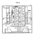
- the operating device 1 is shown with the door open.
- the diagram 8 is arranged, which shows the individual manual control phases, for cyclical execution with program 1, phases 1 to 4 and program 2, phases 1 to 4 with the specified intersection geometries, clearly and visually recognizable.
- This diagram 8 can be formed, for example, by a self-adhesive film which is produced in accordance with the respective intersection or the respective node.
- corresponding diagram illuminated displays 8a are arranged in the diagram.
- the program buttons 5 are to the right of the diagram 8 with keys which can be actuated from the side and associated LEDs 5a arranged.
- Function buttons 6 for various functions with associated light indicators 6a are arranged to the left of the diagram 8.
- the switch 10 which automatically switches off the lighting elements when the control door 3 is closed and, if necessary, switches from manual control to central control.
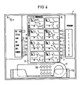
- This diagram 8 can be formed, for example, by a self-adhesive film which is produced in accordance with the respective intersection or the respective node.
- Corresponding diagram light indicators 8a are arranged in diagram 8 for the respective phase.
- the program buttons 5 for the individual phases 1 to 8 are arranged to the right of the diagram 8 with keys which can be actuated from the side and associated light-emitting diodes 5a.
- Function buttons 6 for the most varied functions with associated light indicators 6a are arranged to the left of the diagram 8.
- the step button 7 is not required. It is therefore not applicable.
- the phase from the eight phases that can be switched on is switched on with the corresponding program button 5.
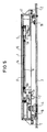
- the operating device 1 has a support part 17, which is designed as a one-piece plastic injection-molded part for receiving all elements of the operating device and with corresponding fastening devices on the cabinet door 2 the control unit is attached.
- the control door 3 is pivotally arranged in the cabinet door 2 and can be closed with the control lock 4.
- a circumferential seal 16 protects the control panel, ie the buttons 5, 6, 7, the displays 5a, 6a, 7a, 8a and the colored phase images 8 against splash or rain water.
- the circuit board 14 on which the respective electronic components are mounted and which - which is not shown here - is connected to the device part 13 via the ribbon cable 12 is protected on its rear side by a cover 15. In the interior of the control door 3, easy-to-read operating instructions for cyclic or acyclic phase sequences can be attached.
- the new control device integrated in the control unit enables the traffic policeman to get a quick and detailed overview.
- the omission of its own housing combined with a low installation effort means that the new operating device offers significantly lower manufacturing costs.
Landscapes
- Physics & Mathematics (AREA)
- General Physics & Mathematics (AREA)
- Lock And Its Accessories (AREA)
- Traffic Control Systems (AREA)
- Road Signs Or Road Markings (AREA)
- Illuminated Signs And Luminous Advertising (AREA)
- Devices For Checking Fares Or Tickets At Control Points (AREA)
- Rotary Switch, Piano Key Switch, And Lever Switch (AREA)
Abstract
Description
- Die Erfindung bezieht sich auf ein Knotenpunkt-Steuergerät mit einer Bedienvorrichtung für die Straßenverkehrstechnik.
- Die Bedienung derartiger Steuergeräte soll in besonderen Fällen, beispielsweise bei Verkehrsunfällen, Demonstrationen o.ä. durch einen eingewiesenen Polizisten über eine Bedienvorrichtung einfach durchgeführt werden können, wobei das Knotenpunktsteuergerät manuell gesteuert wird, um möglichst schnell einen Fahrzeugstau abzubauen oder Sonderfahrten zu ermöglichen. Dabei wurden spezielle, separat angebrachte Bediengeräte mit den erforderlichen Druckschaltern, die sich zum Teil gegenseitig mechanisch verriegeln bzw. auslösen, verwendet. Eine Zustandsanzeige der Schalter erfolgt dabei über Leuchtdioden. Das wetterfeste Gehäuse des Bediengerätes bestand im allgemeinen aus einem Aluminiumguß mit lackierter Oberfläche und wurde in der Regel zusätzlich am Steuergeräteschrank seitlich befestigt. Dies hat jedoch den Nachteil, daß ein derartiges Bediengerät hohe Kosten und eine aufwendige Montage erfordert. Zudem ragt es störend aus dem Geräteschrank heraus und kann dadurch leichter beschädigt werden.
- Aufgabe der Erfindung ist es daher, ein Bediengerät bzw. eine Bedienvorrichtung zu schaffen, welche die obengenannten Nachteile vermeidet und neben einem geringeren Montageaufwand eine leichte, übersichtliche Handhabung gestattet.
- Diese Aufgabe wird erfindungsgemäß bei einem Knotenpunkt-Steuergerät dadurch gelöst, daß die Bedienvorrichtung in der Schranktür des Knotenpunkt-Steuergeräts integriert ist und eine separate Bedientür mit einem Schloß aufweist, und daß die Bedienvorrichtung ein Bedienfeld mit mehreren Programm- und Funktionstasten und zugehörigen Leuchtanzeigen sowie mit einem Schaubild mit zugehörigen Leuchtanzeigen für einzelne Handsteuerphasen aufweist.
- In vorteilhafter Weise ist in der Schranktür die Bedienvorrichtung integriert und weist im Zentrum ein Schaubild für die einzelnen Steuerphasen mit zugehörigen Leuchtdioden auf. Dabei wird in vorteilhafter Weise die momentan laufende Phase angezeigt, so daß der Verkehrspolizist eine schnelle und eindeutige Verkehrsübersicht hat. Zudem kann er auch die folgenden Phasen aufgrund des Schaubildes bereits bildlich erkennen.
- Zweckmäßigerweise sind die Programmtaster und die Funktionstaster seitlich, z.B. links und rechts vom Schaubild, angeordnet und können, weil sie relativ selten bedient werden, von der Seite her betätigbare Tasten aufweisen. Dabei ist es besonders vorteilhaft, eine häufig zu betätigende Taste, beispielsweise den Schrittaster, leicht zugänglich anzuordnen und dabei von vorne bedienbar auszugestalten.
- Die erfindungsgemäße Bedienvorrichtung kann entweder für einen zyklischen oder für einen azyklischen Phasenablauf ausgelegt sein. Für eine zyklische Phasensteuerung per Hand können beispielsweise Zwei verschiedene Steuerprogramme mit jeweils vier Phasen vorgesehen sein. Dabei ist mit den Programmtasten das gewünschte Programm einzuschalten und mit dem Schritt-Taster auf die jeweils folgende Phase weiterzuschalten.
- Ist das Bediengerät für azyklische Phasenabläufe, beispielsweise für 8 unterschiedliche Phasen, ausgelegt, so entfällt der Schritt-Taster und per Hand kann über die Programmtasten eine beliebige Phase von den 8 Phasen eingeschaltet werden.
- In einer vorteilhaften Ausgestaltung der Erfindung ist ein von der Bedientür vorzugsweise beim Schließen betätigbarer Schalter vorgesehen, der die Handsteuerung auf Zentralsteuerung selbsttätig zurückschaltet, falls das Umschalten vergessen wurde.
- In einer weiteren Ausgestaltung der Erfindung ist eine Beleuchtungseinrichtung vorgesehen, die das Bedienfeld insbesondere für den Nachtbetrieb ausleuchtet. Dabei kann ein Ausschalter sowohl für die zusätzliche Beleuchtung als auch für die Anzeigeelemente vorgesehen sein, wobei hierzu zusätzlich der von der Bedientür betätigbare Schalter zweckmäßigerweise dienen kann, so daß mit dem Schließen der Bedientür dieser Schalter auch die Beleuchtungseinrichtung und die Leuchtanzeigen selbsttätig ausschaltet.
- In einer weiteren, zweckmäßigen Ausgestaltung der Erfindung kann ein Telefonhörer innerhalb der Bedienvorrichtung in einer Haltevorrichtung, beispielsweise unterhalb des Schaubildes, vorgesehen sein. Dabei kann der Telefonhörer auch mit einer Wählvorrichtung ausgestattet sein.
- In einer zweckmäßigen Ausgestaltung kann die Bedienvorrichtung über eine streckbare Leitung mit dem Geräteteil des Steuergerätes verbunden sein, so daß die Bedienvorrichtung auch einzeln prüfbar ist oder ohne großen Aufwand ausgetauscht werden kann.
- Im folgenden wird die Erfindung an einem Ausführungsbeispiel anhand der Zeichnung erläutert. Dabei zeigen
- Fig. 1 und 2 ein Knotenpunkt-Steuergerät mit der Bedienvorrichtung in Frontansicht und in Draufsicht (geöffnet),
- Fig. 3 und 4 jeweils eine Bedienvorrichtung mit geöffneter Tür in Frontansicht für zyklischen und azyklischen Phasenablauf,
- Fig. 5 einen Schnitt IV-IV gemäß Fig. 3.
- In Fig. 1 ist ein Knotenpunkt-Steuergerät mit der erfindungsgemäßen Bedienvorrichtung 1 gezeigt. Das Steuergerät weist eine Schranktür 2 mit einem Schrankschloß 18 auf, welches nur von berechtigten Personen geöffnet werden kann. In der Schranktür 2 ist die Bedienvorrichtung 1 mittig integriert und mit einer Bedientür 3 versehen, die ein Schloß 4 aufweist, welches von einem Verkehrspolizisten aufgeschlossen werden kann. Das Schrankschloß 18 hingegen kann von einem Verkehrspolizisten nicht aufgeschlossen werden. Dies ist dem Wartungspersonal vorbehalten. Die Bedientür 3 ist teilweise aufgerissen dargestellt, so daß die Beleuchtungseinrichtung 9 und das Schaubild 8 zu erkennen ist.
- In Fig.2 ist der Schrank von oben gesehen mit abgenommenem Deckel gezeigt, so daß die Bedienvorrichtung 1, die in der Schranktür 2 integriert angeordnet ist, gut zu erkennen ist. Uber eine Verbindungsleitung 12, beispielsweise eine Bandleitung, ist die Bedienvorrichtung 1 mit dem Geräteteil 13 steckbar verbunden, so daß die Bedienvorrichtung 1 unabhängig vom Geräteteil extern geprüft oder auch ohne weiteres getauscht werden kann.
- In Fig. 3 ist die Bedienvorrichtung 1 bei geöffneter Tür gezeigt. Im Zentrum der Bedienvorrichtung 1 ist das Schaubild 8 angeordnet, das die einzelnen Handsteuerphasen, für zyklischen Ablauf mit Programm 1, Phase 1 bis 4 und Programm 2, Phase 1 bis 4 mit den vorgegebenen Kreuzungsgeometrien bildlich und farblich gut erkennbar darstellt. Dieses Schaubild 8 kann beispielsweise von einer selbstklebenden Folie gebildet sein, die entsprechend der jeweiligen Kreuzung bzw. des jeweiligen Knotenpunktes hergestellt wird. Für das jeweilige Programm 1 und 2 und die entsprechenden Phasen sind im Schaubild entsprechende Schaubild-Leuchtanzeigen 8a angeordnet. Die Programmtaster 5 sind bei diesem Ausführungsbeispiel rechts vom Schaubild 8 mit seitlich betätigbaren Tasten und den dazugehörigen Leuchtdioden 5a angeordnet. Links vom Schaubild 8 sind Funktionstaster 6 für die verschiedensten Funktionen mit zugehörigen Leuchtanzeigen 6a angeordnet. Der häufig zu betätigende Schrittaster 7 ist dabei von vorne bedienbar und leicht zugänglich mit einer zugehörigen Leuchtanzeige 6a links angeordnet. Oberhalb, links von den Funktionstasten 6 ist der Schalter 10 angeordnet, der automatisch mit dem Schließen der Bedientür 3 die Beleuchtungselemente ausschaltet und gegebenenfalls von Handsteuerung auf Zentralsteuerung umschaltet. Im unteren Bedienbereich ist in einer Haltevorrichtung 11a ein Telefonhörer 11, der auch eine Wählvorrichtung 11b aufweisen kann, angeordnet.
- In Fig. 4 ist nochmals die Bedienvorrichtung 1 bei geöffneter Tür mit dem Schaubild 8 für eine azyklische Handsteuerung mit 8 Phasen 1 bis 8 gezeigt. Diese sind entsprechend den vorgegebenen Kreuzungsgeometrien bildlich und farblich gut erkennbar dargestellt. Dieses Schaubild 8 kann beispielsweise von einer selbstklebenden Folie gebildet sein, die entsprechend der jeweiligen Kreuzung bzw. des jeweiligen Knotenpunktes hergestellt wird. Für die jeweilige Phase sind im Schaubild 8 entsprechende Schaubild-Leuchtanzeigen 8a angeordnet. Die Programmtaster 5 für die einzelnen Phasen 1 bis 8 sind bei diesem Ausführungsbeispiel rechts vom Schaubild 8 mit seitlich betätigbaren Tasten und dazugehörigen Leuchtdioden 5a angeordnet. Links vom Schaubild 8 sind Funktionstaster 6 für die verschiedensten Funktionen mit zugehörigen Leuchtanzeigen 6a angeordnet. Der Schrittaster 7 ist nicht erforderlich. Er entfällt daher. Die beliebig einschaltbare Phase aus den acht Phasen wird mit dem entsprechenden Programmtaster 5 eingeschaltet.
- In Fig.5 ist die Schnittzeichnung V-V gemäß der Fig.3 dargestellt. Die Bedienvorrichtung 1 weist ein Trageteil 17 auf, welches als ein einstückiges Kunststoff-Spritzteil zur Aufnahme aller Elemente der Bedienvorrichtung ausgebildet ist und mit entsprechenden Befestigungsvorrichtungen an der Schranktür 2 des Steuergerätes befestigt ist. Die Bedientür 3 ist in der Schranktür 2 schwenkbar angeordnet und kann mit den Bedienschloß 4 verschlossen werden. Eine umlaufende Dichtung 16 schützt das Bedienteil, d.h. die Taster 5,6,7, die Anzeigen 5a,6a,7a,8a und die farbigen Phasenbilder 8 gegen Spritz- oder Regenwasser. Die Leiterplatte 14, auf der die jeweiligen elektronischen Bauteile montiert sind, und die - was hier nicht gezeigt ist - über die Bandleitung 12 mit dem Geräteteil 13 verbunden ist, ist an ihrer Rückseite durch eine Abdeckung 15 geschützt. Im inneren der Bedientür 3 kann eine gut lesbare Bedienanleitung für zyklischen oder azyklischen Phasenablauf angebracht sein.
- Die neue, im Steuergerät integrierte Bedienvorrichtung ermöglicht dem Verkehrspolizisten eine schnelle und ins Detail gehende Übersicht. Darüber hinaus bietet die neue Bedienvorrichtung durch den Wegfall eines eigenen Gehäuses, verbunden mit einem geringen Montageaufwand wesentlich niedrigere Herstellungskosten.
Claims (7)
- Knotenpunkt-Steuergerät mit Bedienvorrichtung für die Straßenverkehrstechnik,
dadurch gekennzeichnet, daß die Bedienvorrichtung (1) in der Schranktür (2) des Knotenpunkt-Steuergeräts integriert ist und eine separate Bedientür (3) mit einem Schloß (4) aufweist, und daß die Bedienvorrichtung (1) ein Bedienfeld mit mehreren Programm- und Funktionstasten (5,6,7) und zugehörigen Leuchtanzeigen (5a,6a,7a) sowie mit einem Schaubild (8) mit zugehörigen Leuchtanzeigen (8a) für einzelne Handsteuerphasen aufweist. - Knotenpunkt-Steuergerät nach Anspruch 1,
dadurch gekennzeichnet, daß die Programm- und Funktions-Taster (5,6,7) seitlich vom Schaubild (8) angeordnet sind, wobei ein häufig zu betätigender Taster (7) besonders leicht zugänglich angeordnet ist. - Knotenpunkt-Steuergerät nach Anspruch 1 oder 2,
dadurch gekennzeichnet, daß die Bedienvorrichtung (1) einen von der Bedientür (3) betätigbaren Schalter (10) aufweist, der gegebenenfalls die Handsteuerung auf Zentralsteuerung zurückschaltet. - Knotenpunkt-Steuergerät nach Anspruch 1,2 oder 3,
dadurch gekennzeichnet, daß die Bedienvorrichtung (1) eine das Bedienfeld ausleuchtende Beleuchtungseinrichtung (9) aufweist, die vom Schalter (10) ausschaltbar ist. - Knotenpunkt-Steuergerät nach einem der vorhergehenden Ansprüche, dadurch gekennzeichnet, daß innerhalb der Bedienvorrichtung (1) ein Telefonhörer (11) angeordnet ist.
- Knotenpunkt-Steuergerät nach einem der vorhergehenden Ansprüche, dadurch gekennzeichnet, daß das Geräteteil (13) des Knotenpunkt-Steuergerätes mit der Bedienvorrichtung (1) über eine steckbare Leitung (12) verbunden ist.
- Knotenpunkt-Steuergerät nach einem der vorhergehenden Ansprüche, dadurch gekennzeichnet, daß die Bedienvorrichtung entweder für einen zyklischen oder für einen azyklischen Phasenablauf ausgelegt ist.
Applications Claiming Priority (2)
| Application Number | Priority Date | Filing Date | Title |
|---|---|---|---|
| DE9003989U DE9003989U1 (de) | 1990-04-05 | 1990-04-05 | Knotenpunkt-Steuergerät mit Bedienvorrichtung für die Straßenverkehrstechnik |
| DE9003989U | 1990-04-05 |
Publications (3)
| Publication Number | Publication Date |
|---|---|
| EP0450160A2 true EP0450160A2 (de) | 1991-10-09 |
| EP0450160A3 EP0450160A3 (en) | 1992-04-01 |
| EP0450160B1 EP0450160B1 (de) | 1994-04-20 |
Family
ID=6852676
Family Applications (1)
| Application Number | Title | Priority Date | Filing Date |
|---|---|---|---|
| EP90123242A Expired - Lifetime EP0450160B1 (de) | 1990-04-05 | 1990-12-04 | Knotenpunkt-Steuergerät mit Bedienvorrichtung für die Strassenverkehrstechnik |
Country Status (5)
| Country | Link |
|---|---|
| EP (1) | EP0450160B1 (de) |
| AT (1) | ATE104787T1 (de) |
| DE (2) | DE9003989U1 (de) |
| DK (1) | DK0450160T3 (de) |
| ES (1) | ES2052141T3 (de) |
-
1990
- 1990-04-05 DE DE9003989U patent/DE9003989U1/de not_active Expired - Lifetime
- 1990-12-04 ES ES90123242T patent/ES2052141T3/es not_active Expired - Lifetime
- 1990-12-04 EP EP90123242A patent/EP0450160B1/de not_active Expired - Lifetime
- 1990-12-04 DE DE59005463T patent/DE59005463D1/de not_active Expired - Fee Related
- 1990-12-04 AT AT9090123242T patent/ATE104787T1/de active
- 1990-12-04 DK DK90123242.1T patent/DK0450160T3/da active
Non-Patent Citations (1)
| Title |
|---|
| HASLER MITTEILLUNGEN, Bd. 37, Nr. 2/3, September 1978, BERN, CH; Seiten 49 - 52; (J.F. MAAGD ET AL.): 'Verkehrsregelungsanlage ES' * |
Also Published As
| Publication number | Publication date |
|---|---|
| ATE104787T1 (de) | 1994-05-15 |
| DK0450160T3 (da) | 1994-06-20 |
| DE59005463D1 (de) | 1994-05-26 |
| EP0450160B1 (de) | 1994-04-20 |
| DE9003989U1 (de) | 1990-06-28 |
| ES2052141T3 (es) | 1994-07-01 |
| EP0450160A3 (en) | 1992-04-01 |
Similar Documents
| Publication | Publication Date | Title |
|---|---|---|
| DE102007046999B3 (de) | Betätiger | |
| DE2659160C2 (de) | Zentrale Schaltmatrix zum selektiven Verbinden von mehreren Zentraleinheiten mit mehreren peripheren Einheiten einer Datenverarbeitungsanlage | |
| DE3019021A1 (de) | Beleuchtungseinrichtung fuer einen drucktastenschalter | |
| DE20311729U1 (de) | Schalthebel mit Display | |
| EP0450160B1 (de) | Knotenpunkt-Steuergerät mit Bedienvorrichtung für die Strassenverkehrstechnik | |
| DE3511026C2 (de) | ||
| EP1873596B1 (de) | Tragbarer Funkfernsteuerungssender mit beleuchteten Tasten | |
| DE10118120C1 (de) | Beleuchtungssystem für Handhaben | |
| DE3425190C2 (de) | ||
| EP1101654A2 (de) | Beleuchtungsvorrichtung für Gerätegruppen in Kraftfahrzeugen | |
| DE19851505A1 (de) | Schaltelement | |
| DE3248911C2 (de) | Informationsgerät für den Fahrgastraum öffentlicher Verkehrsmittel | |
| EP0999087B1 (de) | Multifunktionsanzeige für Kraftfahrzeuge | |
| DE1655085C3 (de) | Drucktastenschalter für Fahrzeuge | |
| DE4206335A1 (de) | Blinkgeberschalteinrichtung | |
| DE908946C (de) | Drehbarer Stellungsanzeiger fuer Netznachbildungen, insbesondere Bausteinschaltbilder | |
| DE4031364A1 (de) | Vorrichtung fuer die manuelle eingabe von fuer eine technische anlage bestimmten steuerdaten und fuer die anzeige von parametern der technischen anlage | |
| EP1566310B1 (de) | Schalterleiste | |
| DE8812334U1 (de) | Anzeigetafel für Kraftfahrzeuge | |
| DE29604613U1 (de) | Notrufsäule | |
| DE102023121782A1 (de) | Fluchtwegsicherungsvorrichtung mit Statusanzeige | |
| DE102019100830A1 (de) | Panikschloss mit Informationsbeleuchtung | |
| DE202007004859U1 (de) | Anzeigeeinheit | |
| DE4413377B4 (de) | Verfahren zur Darstellung von mindestens zwei numerischen Informationen | |
| DE10329114B3 (de) | Schaltstellungsanzeiger für ein Installationsgerät sowie Installationsgerät mit einem verschwenkbaren Betätigungsorgan und einem Schaltstellungsanzeiger |
Legal Events
| Date | Code | Title | Description |
|---|---|---|---|
| PUAI | Public reference made under article 153(3) epc to a published international application that has entered the european phase |
Free format text: ORIGINAL CODE: 0009012 |
|
| 17P | Request for examination filed |
Effective date: 19901220 |
|
| AK | Designated contracting states |
Kind code of ref document: A2 Designated state(s): AT BE CH DE DK ES FR GB GR IT LI LU NL SE |
|
| PUAL | Search report despatched |
Free format text: ORIGINAL CODE: 0009013 |
|
| AK | Designated contracting states |
Kind code of ref document: A3 Designated state(s): AT BE CH DE DK ES FR GB GR IT LI LU NL SE |
|
| 17Q | First examination report despatched |
Effective date: 19921201 |
|
| GRAA | (expected) grant |
Free format text: ORIGINAL CODE: 0009210 |
|
| AK | Designated contracting states |
Kind code of ref document: B1 Designated state(s): AT BE CH DE DK ES FR GB GR IT LI LU NL SE |
|
| REF | Corresponds to: |
Ref document number: 104787 Country of ref document: AT Date of ref document: 19940515 Kind code of ref document: T |
|
| REF | Corresponds to: |
Ref document number: 59005463 Country of ref document: DE Date of ref document: 19940526 |
|
| REG | Reference to a national code |
Ref country code: DK Ref legal event code: T3 |
|
| REG | Reference to a national code |
Ref country code: ES Ref legal event code: FG2A Ref document number: 2052141 Country of ref document: ES Kind code of ref document: T3 |
|
| ITF | It: translation for a ep patent filed | ||
| GBT | Gb: translation of ep patent filed (gb section 77(6)(a)/1977) |
Effective date: 19940627 |
|
| REG | Reference to a national code |
Ref country code: GR Ref legal event code: FG4A Free format text: 3011783 |
|
| ET | Fr: translation filed | ||
| EAL | Se: european patent in force in sweden |
Ref document number: 90123242.1 |
|
| PLBE | No opposition filed within time limit |
Free format text: ORIGINAL CODE: 0009261 |
|
| STAA | Information on the status of an ep patent application or granted ep patent |
Free format text: STATUS: NO OPPOSITION FILED WITHIN TIME LIMIT |
|
| 26N | No opposition filed | ||
| PGFP | Annual fee paid to national office [announced via postgrant information from national office to epo] |
Ref country code: GB Payment date: 19981210 Year of fee payment: 9 Ref country code: ES Payment date: 19981210 Year of fee payment: 9 Ref country code: BE Payment date: 19981210 Year of fee payment: 9 |
|
| PGFP | Annual fee paid to national office [announced via postgrant information from national office to epo] |
Ref country code: AT Payment date: 19981211 Year of fee payment: 9 |
|
| PGFP | Annual fee paid to national office [announced via postgrant information from national office to epo] |
Ref country code: DK Payment date: 19981214 Year of fee payment: 9 |
|
| PGFP | Annual fee paid to national office [announced via postgrant information from national office to epo] |
Ref country code: LU Payment date: 19981216 Year of fee payment: 9 |
|
| PGFP | Annual fee paid to national office [announced via postgrant information from national office to epo] |
Ref country code: NL Payment date: 19981217 Year of fee payment: 9 |
|
| PGFP | Annual fee paid to national office [announced via postgrant information from national office to epo] |
Ref country code: GR Payment date: 19981218 Year of fee payment: 9 Ref country code: FR Payment date: 19981218 Year of fee payment: 9 |
|
| PGFP | Annual fee paid to national office [announced via postgrant information from national office to epo] |
Ref country code: SE Payment date: 19981222 Year of fee payment: 9 |
|
| PGFP | Annual fee paid to national office [announced via postgrant information from national office to epo] |
Ref country code: DE Payment date: 19990219 Year of fee payment: 9 |
|
| PGFP | Annual fee paid to national office [announced via postgrant information from national office to epo] |
Ref country code: CH Payment date: 19990311 Year of fee payment: 9 |
|
| PG25 | Lapsed in a contracting state [announced via postgrant information from national office to epo] |
Ref country code: LU Free format text: LAPSE BECAUSE OF NON-PAYMENT OF DUE FEES Effective date: 19991204 Ref country code: GB Free format text: LAPSE BECAUSE OF NON-PAYMENT OF DUE FEES Effective date: 19991204 Ref country code: DK Free format text: LAPSE BECAUSE OF NON-PAYMENT OF DUE FEES Effective date: 19991204 Ref country code: AT Free format text: LAPSE BECAUSE OF NON-PAYMENT OF DUE FEES Effective date: 19991204 |
|
| PG25 | Lapsed in a contracting state [announced via postgrant information from national office to epo] |
Ref country code: SE Free format text: LAPSE BECAUSE OF NON-PAYMENT OF DUE FEES Effective date: 19991205 |
|
| PG25 | Lapsed in a contracting state [announced via postgrant information from national office to epo] |
Ref country code: LI Free format text: LAPSE BECAUSE OF NON-PAYMENT OF DUE FEES Effective date: 19991231 Ref country code: GR Free format text: LAPSE BECAUSE OF NON-PAYMENT OF DUE FEES Effective date: 19991231 Ref country code: CH Free format text: LAPSE BECAUSE OF NON-PAYMENT OF DUE FEES Effective date: 19991231 Ref country code: BE Free format text: LAPSE BECAUSE OF NON-PAYMENT OF DUE FEES Effective date: 19991231 |
|
| BERE | Be: lapsed |
Owner name: SIEMENS A.G. Effective date: 19991231 |
|
| PG25 | Lapsed in a contracting state [announced via postgrant information from national office to epo] |
Ref country code: NL Free format text: LAPSE BECAUSE OF NON-PAYMENT OF DUE FEES Effective date: 20000701 |
|
| GBPC | Gb: european patent ceased through non-payment of renewal fee |
Effective date: 19991204 |
|
| EUG | Se: european patent has lapsed |
Ref document number: 90123242.1 |
|
| PG25 | Lapsed in a contracting state [announced via postgrant information from national office to epo] |
Ref country code: FR Free format text: LAPSE BECAUSE OF NON-PAYMENT OF DUE FEES Effective date: 20000831 |
|
| NLV4 | Nl: lapsed or anulled due to non-payment of the annual fee |
Effective date: 20000701 |
|
| REG | Reference to a national code |
Ref country code: DK Ref legal event code: EBP |
|
| PG25 | Lapsed in a contracting state [announced via postgrant information from national office to epo] |
Ref country code: DE Free format text: LAPSE BECAUSE OF NON-PAYMENT OF DUE FEES Effective date: 20001003 |
|
| REG | Reference to a national code |
Ref country code: FR Ref legal event code: ST |
|
| PG25 | Lapsed in a contracting state [announced via postgrant information from national office to epo] |
Ref country code: ES Free format text: LAPSE BECAUSE OF NON-PAYMENT OF DUE FEES Effective date: 20001205 |
|
| REG | Reference to a national code |
Ref country code: ES Ref legal event code: FD2A Effective date: 20010113 |
|
| PG25 | Lapsed in a contracting state [announced via postgrant information from national office to epo] |
Ref country code: IT Free format text: LAPSE BECAUSE OF NON-PAYMENT OF DUE FEES;WARNING: LAPSES OF ITALIAN PATENTS WITH EFFECTIVE DATE BEFORE 2007 MAY HAVE OCCURRED AT ANY TIME BEFORE 2007. THE CORRECT EFFECTIVE DATE MAY BE DIFFERENT FROM THE ONE RECORDED. Effective date: 20051204 |