EP0448547B1 - Fahrzeug Belüftungsvorrichtung - Google Patents
Fahrzeug Belüftungsvorrichtung Download PDFInfo
- Publication number
- EP0448547B1 EP0448547B1 EP19910890055 EP91890055A EP0448547B1 EP 0448547 B1 EP0448547 B1 EP 0448547B1 EP 19910890055 EP19910890055 EP 19910890055 EP 91890055 A EP91890055 A EP 91890055A EP 0448547 B1 EP0448547 B1 EP 0448547B1
- Authority
- EP
- European Patent Office
- Prior art keywords
- air
- cabin
- valve
- vehicle
- fresh
- Prior art date
- Legal status (The legal status is an assumption and is not a legal conclusion. Google has not performed a legal analysis and makes no representation as to the accuracy of the status listed.)
- Expired - Lifetime
Links
- 230000003213 activating effect Effects 0.000 claims description 28
- 230000005611 electricity Effects 0.000 claims description 5
- XLYOFNOQVPJJNP-UHFFFAOYSA-N water Substances O XLYOFNOQVPJJNP-UHFFFAOYSA-N 0.000 claims description 5
- 230000000149 penetrating effect Effects 0.000 claims description 4
- 239000000446 fuel Substances 0.000 description 3
- 238000010586 diagram Methods 0.000 description 2
- 230000000694 effects Effects 0.000 description 2
- 238000009423 ventilation Methods 0.000 description 2
- 238000010792 warming Methods 0.000 description 2
- 238000005452 bending Methods 0.000 description 1
- 238000004140 cleaning Methods 0.000 description 1
- 230000008878 coupling Effects 0.000 description 1
- 238000010168 coupling process Methods 0.000 description 1
- 238000005859 coupling reaction Methods 0.000 description 1
- 230000006378 damage Effects 0.000 description 1
- 230000002265 prevention Effects 0.000 description 1
- 230000000630 rising effect Effects 0.000 description 1
Images
Classifications
-
- B—PERFORMING OPERATIONS; TRANSPORTING
- B60—VEHICLES IN GENERAL
- B60H—ARRANGEMENTS OF HEATING, COOLING, VENTILATING OR OTHER AIR-TREATING DEVICES SPECIALLY ADAPTED FOR PASSENGER OR GOODS SPACES OF VEHICLES
- B60H1/00—Heating, cooling or ventilating [HVAC] devices
- B60H1/00421—Driving arrangements for parts of a vehicle air-conditioning
- B60H1/00428—Driving arrangements for parts of a vehicle air-conditioning electric
-
- B—PERFORMING OPERATIONS; TRANSPORTING
- B60—VEHICLES IN GENERAL
- B60H—ARRANGEMENTS OF HEATING, COOLING, VENTILATING OR OTHER AIR-TREATING DEVICES SPECIALLY ADAPTED FOR PASSENGER OR GOODS SPACES OF VEHICLES
- B60H1/00—Heating, cooling or ventilating [HVAC] devices
- B60H1/24—Devices purely for ventilating or where the heating or cooling is irrelevant
- B60H1/248—Air-extractors, air-evacuation from the vehicle interior
-
- Y—GENERAL TAGGING OF NEW TECHNOLOGICAL DEVELOPMENTS; GENERAL TAGGING OF CROSS-SECTIONAL TECHNOLOGIES SPANNING OVER SEVERAL SECTIONS OF THE IPC; TECHNICAL SUBJECTS COVERED BY FORMER USPC CROSS-REFERENCE ART COLLECTIONS [XRACs] AND DIGESTS
- Y02—TECHNOLOGIES OR APPLICATIONS FOR MITIGATION OR ADAPTATION AGAINST CLIMATE CHANGE
- Y02T—CLIMATE CHANGE MITIGATION TECHNOLOGIES RELATED TO TRANSPORTATION
- Y02T10/00—Road transport of goods or passengers
- Y02T10/80—Technologies aiming to reduce greenhouse gasses emissions common to all road transportation technologies
- Y02T10/88—Optimized components or subsystems, e.g. lighting, actively controlled glasses
Definitions
- This invention related to an automatic ventilating device for for a cabin of a vehicle such as a passenger car or a truck, more particularly, to a ventilating device which prevents temperature in a cabin of a vehicle from going too high during the vehicle's parking time.
- temperature in a cabin of a vehicle raises, during its parking time with the engine stopped, to an extremely high degree which we can never experience in our daily life. For instance, if a vehicle is left under the burning sun in the summer, temperature in a cabin of the vehicle goes up to 60 to 70 degrees centigrade.
- a device according to the preamble of claim 1 is known, for example, from US-A-4.804.140.
- a principle object of the present invention is to provide a cabin ventilating device which is driven by solar energy and ventilates air in a cabin of a vehicle in parking without consuming fuel and battery, and which is hardly broken and free from the possibility of theft.
- a ventilating device has an exhaust path penetrating through a portion of a vehicles body to exhaust air in the cabin of a vehicle to outside, a fresh-air conducting path penetrating through a portion of the vehicle's body to conduct fresh air into the cabin of the vehicle, a valve arranged in said exhaust path, an air-flow activating means arranged in series to this valve, a valve arranged in said fresh-air conducting path, an air-flow activating means arranged in series to this valve, solar cells which are arranged on an external surface of the vehicle to receive sunlight and generate electricity, and an electric circuit which drives each of said air-flow activating means by making use of electricity from said solar cells.
- this ventilating device is quite energy saving.
- the solar cells can generate and supply as much electricity as required by the air-flow activating means.
- electric energy generated by the solar cells is little, and the ventilating device does not work.
- the exhaust path and the fresh-air conducting path penetrate through a portion of the vehicle's body, and there are valves arranged near and to the exterior side from the air-flow activating means, so that the driver does not have to worry about destruction or theft during parking time.
- the valves are kept closed when the air-flow activating means does not work, and this feature prevents cool air from coming into the cabin when running, especially in the winter, and a warming effect in the cabin does not go down.
- the inlet of the exhaust path should be arranged on a ceiling of the cabin, while the inlet of the fresh-air conducting path should be arranged on an external face of the vehicles body.
- a bulkhead is arranged in the aforesaid exhaust path and the aforesaid fresh-air conducting path respectively to the exterior side from the aforesaid valves. This bulkhead can prevent rain water and the like from coming into the cabin from the exhaust path and the fresh-air conducting path when driving on a rainy day.
- a power switch In the electric circuit coupling said solar cells to each of said air-flow activating means, a power switch, a switch correlating to and engine key switch, and a thermostat which works according to temperature in the cabin are arranged in series.
- the air-flow activating means automatically works only when the engine does not run and temperature in the cabin is high, and the solar cells may be of compact size with small capacity.
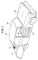
- Fig.1 is a perspective view showing a portion of a car to which the present invention is applied.
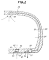
- Fig.2 is a sectional view of a vehicles body along a center line of the exhaust path.
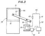
- Fig.3 is a circuit diagram with a rear view of a valve in the exhaust path in a close position.
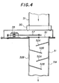
- Fig.4 is a sectional view of the exhaust path at the valve.
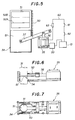
- Fig.5 is a circuit diagram with a rear view of the same valve in an open position.
- Fig.6 is a size view of a valve in an exhaust path of another embodiment of the present invention.
- Fig.7 is a plan of the same valve.
- a solar cell 10 having a light collecting board which receives sunlight is mounted on a top face of a rear section (trunk) of a vehicles body 20.
- the solar cell 10 may be mounted on the ceiling 22 of the vehicle's body 20 or on a surface of a bonnet 23, or on other section exposed to sunlight.
- a convertor which converts a direct current generated by the solar cell 10 to an alternating current and a battery which stores electric energy generated by the solar cell 10 are incorporated.
- an exhaust path 31 which exhausts air in a cabin 24 through a piping running through the vehicle's body 20 to outside and a fresh-air conducting path 41 which conducts fresh air from outside into the cabin 24 are arranged.
- the exhaust path 31 takes out air from an inlet port 32 on the ceiling 22 of the cabin 24 and exhaust the air from an outlet port 33 on an external face of a floor panel 23.
- the fresh-air conducting path 41 sends fresh air took from an inlet port 43 on an external face of the floor panel 25 into the cabin 24 from an outlet port 42 on an internal face of the floor panel 25.
- An air-flow activating unit 30 which works using said solar cell 10 as a power source is arranged on said exhaust path 31.
- This air-flow activating unit 30 comprises, for instance, an electrically operated fan, and discharges air in the cabin to outside.
- a valve 34 which opens and closes the exhaust path 31, is arranged to the exterior side from the air-flow activating unit 30.
- the valve 34 opens when the air-flow activating unit 30 works in accordance with input of electric power from the solar cells.
- an air-flow activating unit 40 comprising an electrically operated fan to take air from outside into the cabin is arranged on the fresh-air conducting path 41, and a valve 44 to open or close the fresh-air conducting path 41 is arranged to the exterior side from said air-flow activating unit 40.
- air which is warmed during parking time and gathers near the ceiling is forcibly discharged to outside by the air-flow activating unit 30 via the exhaust path 31 with its opening on the ceiling, while cool air with relatively low temperature in the shadow under the vehicle's body 20 is introduced into the cabin by the air-flow activating unit 40 via the fresh-air conducting path 41 with its opening on the external face of the floor panel 25.
- Configuration and operation of the air-flow activating unit 40 and the valve 44 are basically the same as those of the air-flow activating unit 30 and the valve 34 on the exhaust path 31, which are described in detail later, and can easily be understood by referring to the description thereof.
- the valve 31 arranged on the exhaust path 31 is driven by a solenoid actuator 35.
- a valve body 31 is coupled to a link 37 driven by a plunger 36 of the solenoid actuator 35, and when the solenoid actuator 35 is activated, the link 37 makes the valve body 51 slide against a return spring 50, and opens the exhaust path 31 (Refer to Fig.5) .
- An electric circuit 60 which drives the air-flow activating unit 30 and the valve 34 with the solar cell 10 has a series combination of a first switch 61 as a power switch, a second switch 62 which works in correlation to an engine key switch of the vehicle not shown in the drawings, and a thermostat 63 which works according to change of temperature in the cabin.
- Said second switch 62 correlates to the engine key switch so that it turns ON when the engine switch is turned OFF and it turns OFF when the engine switch is turned ON.
- a temperature valve at which the thermostat 63 starts working by closing its contact, can be set freely. For instance, the contact will be closed when the temperature in the cabin rises above 30 degrees centigrade.
- the second switch 62 correlating to said engine key turns ON, and if the first switch 61 as a power switch is kept ON, the valve 34 and 44 will automatically open and simultaneously the air-flow activating units 30 and 40 start working when the thermostat 63 starts working by closing its contact in accordance with temperature increase in the cabin.
- the air-flow activating units 30 and 40 do not work. As they work only when temperature in the cabin rises and ventilation is required, a capacity of the solar cell 10 can be minimized, which also means the possibility of minimizing its size.Note that, on rainy or cloudy days or at night when electric energy generation rate of the solar cell 10 is low, the air-flow activating units 30 and 40 do not work, which is preferable in view of the durability of the air-flow activating units 30 and 40.
- valves 34 and 44 close the exhaust path 31 and the fresh-air conducting path 41 respectively, so that, when driving, especially in the winter, fresh air with low temperature is prevented from coming into the cabin and also loss of warming efficiency does not occur.
- bulkheads 52A and 52B are arranged at a specified interval alternately to the exterior side from the valve 34 in the exhaust path 31 to prevent water such as rainwater from coming into the inside.
- the bulkheads 52A are fixed on a a wall 31A of the exhaust path 31 at a certain interval, and the bulkheads 52B are fixed at a certain interval on the wall 31B of the exhaust path 31 which is facing the wall 31A.
- Combination of these bulkheads 52A and 52B forms a path bending zigzag to prevent water such as rainwater from coming into the cabin when driving on a rainy day or when cleaning the car.
- These bulkheads 52A and 52B are also arranged to the exterior side from the valve 44 in the fresh-air conducting path 41.
- Fig.6 and Fig.7 snow another embodiment of the valve 34(44).
- the valve body 51 is directly connected to the plunger 36 of the solenoid actuator 35. Note that the plunger 36 is biased by the return spring 50 to the close position of the valve 34.
Landscapes
- Physics & Mathematics (AREA)
- Thermal Sciences (AREA)
- Engineering & Computer Science (AREA)
- Mechanical Engineering (AREA)
- Air-Conditioning For Vehicles (AREA)
Claims (1)
- Eine Fahrzeugbelüftungsvorrichtung, die einer Kabine (24) eines Fahrzeuges Luft zuführt und die Temperatur in der Kabine senkt, mit einer Auslaßluftleitung (31), die durch einen Teil des Fahrzeuges führt, um Luft von einer Kabine (24) des Fahrzeuges nach außen zu bringen, einer Frischluftzufuhrleitung (41), die durch einen Teil des Fahrzeuges führt, um der Kabine Frischluft zuzuführen, einem Ventil (34), das in der Auslaßleitung (31) vorgesehen ist, mit einem Luftbewegungsmittel (30), das in der Auslaßllufteitung (31) vorgesehen und zum Ventil (34) in Serie geschalten ist, mit einem Ventil (44), das in der Frischluftzufuhrleitung (41) ist, einem Luftbewegungsmittel (40) das in der Frischluftzuleitung (41) vorgesehen und zum Ventil (44) in Serie geschalten ist, mit einer Solarzelle, die an einer äußeren Oberfläche (22, 23) des Fahrzeuges angeordnet ist, um Sonnenlicht zu empfangen, um elektrischen Strom zu erzeugen und mit einem elektrischen Kreis (60), der jedes der Luftbewegungsmittel (30, 40), wobei jedes der Luftbewegungsmittel (30, 40) ein elektrisch betätigter Ventilator ist, und der Ventile (34, 44), mit Elektrizität versorgt, die durch die Solarzelle (10) erzeugt wird, dadurch gekennzeichnet,
daß die Auslaßluftleitung (31) eine Einlaßöffnung (32) an einer Oberseite (22) der Kabine (24) aufweist, eine Auslaßöffnung (33) an der Außenseite eines Bodenteiles (23) des Fahrzeugkörpers (20) aufweist, und eine Leitung, die durch den Fahrzeugkörper verläuft, um die Einlaß- mit der Auslaßöffnung der Auslaßluftleitung zu verbinden,
daß die Frischluftzufuhrleitung (41) eine Einlaßöffnung (43) auf der Außenseite des Bodens (23) des Fahrzeugkörpers (20) aufweist,
daß jedes Ventil (34, 44) außerhalb des elektrisch betätigten Ventilators (30, 40) vorgesehen ist und einen Ventilkörper aufweist, der durch eine Spule (35) in die geöffnete Lage und durch eine Feder (50) in die geschlossene Lage gebracht wird,
daß eine Mehrzahl von Abweisern (52A, 52B), in abwechselnder Richtung angeordnet, in der Auslaßluftleitung (31) im Teil außerhalb des Ventiles (34) angeordnet sind, um das Eindringen von Regenwasser vom Äußeren in die Kabine (24) zu verhindern,
daß eine Mehrzahl von Abweisern (52A, 52B) in abwechselnder Richtung angeordnet, in der Frischluftleitung (41) im Teil außerhalb des Ventiles (44) angeordnet sind, um das Eindringen von Regenwasser vom Äußeren in die Kabine (24) zu verhindern, und
daß der elektrische Kreis (60) eine Serienschaltung eines Ein-/Ausschalters (61), eines Thermostates, der in Abhängigkeit von der Temperatur in der Kabine (24) reagiert und eines Schalters (62), der automatisch ausschaltet, wenn ein Startschlüssel des Fahrzeuges gedreht wird, aufweist.
Applications Claiming Priority (4)
| Application Number | Priority Date | Filing Date | Title |
|---|---|---|---|
| JP29517/90 | 1990-03-22 | ||
| JP1990029517U JP2583700Y2 (ja) | 1990-03-22 | 1990-03-22 | 車内換気装置 |
| JP6518990U JPH0423509U (de) | 1990-06-20 | 1990-06-20 | |
| JP65189/90 | 1990-06-20 |
Publications (2)
| Publication Number | Publication Date |
|---|---|
| EP0448547A1 EP0448547A1 (de) | 1991-09-25 |
| EP0448547B1 true EP0448547B1 (de) | 1993-12-08 |
Family
ID=26367728
Family Applications (1)
| Application Number | Title | Priority Date | Filing Date |
|---|---|---|---|
| EP19910890055 Expired - Lifetime EP0448547B1 (de) | 1990-03-22 | 1991-03-21 | Fahrzeug Belüftungsvorrichtung |
Country Status (2)
| Country | Link |
|---|---|
| EP (1) | EP0448547B1 (de) |
| DE (1) | DE69100732T2 (de) |
Cited By (4)
| Publication number | Priority date | Publication date | Assignee | Title |
|---|---|---|---|---|
| FR2682645A1 (fr) * | 1991-10-18 | 1993-04-23 | Renault | Procede et dispositif de ventilation statique d'un habitacle de vehicule automobile. |
| GB2274003A (en) * | 1992-12-14 | 1994-07-06 | Shunji Ohba | Car ventilating device |
| US5486138A (en) * | 1994-07-20 | 1996-01-23 | Sorensen; Jens O. | Air-pollution reduction method and system for the interior of an automobile |
| WO2004011287A1 (en) * | 2002-07-31 | 2004-02-05 | Michele Squeo | System for venting the passenger compartment of a vehicle |
Family Cites Families (3)
| Publication number | Priority date | Publication date | Assignee | Title |
|---|---|---|---|---|
| US2161728A (en) * | 1936-03-23 | 1939-06-06 | Stout Engineering Lab Inc | Ventilator |
| US4804140A (en) * | 1987-12-24 | 1989-02-14 | Cantrell Ricky L | Solar powered ventilating system for vehicles |
| GB8813547D0 (en) * | 1988-06-08 | 1988-07-13 | Oemec Taiwan Corp | Crease eliminating device for sewing machines solar-powered cooling/heating system |
-
1991
- 1991-03-21 EP EP19910890055 patent/EP0448547B1/de not_active Expired - Lifetime
- 1991-03-21 DE DE1991600732 patent/DE69100732T2/de not_active Expired - Fee Related
Cited By (5)
| Publication number | Priority date | Publication date | Assignee | Title |
|---|---|---|---|---|
| FR2682645A1 (fr) * | 1991-10-18 | 1993-04-23 | Renault | Procede et dispositif de ventilation statique d'un habitacle de vehicule automobile. |
| GB2274003A (en) * | 1992-12-14 | 1994-07-06 | Shunji Ohba | Car ventilating device |
| GB2274003B (en) * | 1992-12-14 | 1996-01-17 | Shunji Ohba | Car ventilating device |
| US5486138A (en) * | 1994-07-20 | 1996-01-23 | Sorensen; Jens O. | Air-pollution reduction method and system for the interior of an automobile |
| WO2004011287A1 (en) * | 2002-07-31 | 2004-02-05 | Michele Squeo | System for venting the passenger compartment of a vehicle |
Also Published As
| Publication number | Publication date |
|---|---|
| EP0448547A1 (de) | 1991-09-25 |
| DE69100732T2 (de) | 1994-06-30 |
| DE69100732D1 (de) | 1994-01-20 |
Similar Documents
| Publication | Publication Date | Title |
|---|---|---|
| US5205782A (en) | Car ventilating system | |
| US4658597A (en) | Solar powered automobile cooling system | |
| US5433660A (en) | Automatic vehicular ventilating system | |
| EP0448547B1 (de) | Fahrzeug Belüftungsvorrichtung | |
| JPS5951451B2 (ja) | 自動車用換気装置 | |
| JPS6021084B2 (ja) | 自動車用換気装置 | |
| US20040217179A1 (en) | Car regulating thermostat | |
| KR940008418B1 (ko) | 차량승차실내의 환기장치 | |
| JPH06507592A (ja) | 車両の乗客室の自然換気装置 | |
| CN210851959U (zh) | 一种车载独立通风系统 | |
| JPS60261725A (ja) | 車内温度自動調整システム | |
| CN208343897U (zh) | 以太阳能为能源的半导体制冷加热汽车车窗恒温系统 | |
| US20030013405A1 (en) | Ventilation device and system for vehicles | |
| JP3004225U (ja) | 乗物用太陽電池式換気装置 | |
| CN107719068A (zh) | 一种机动车用太阳能降温装置 | |
| JPH04321424A (ja) | エンジン停止時の車内換気装置付き車 | |
| JPS5885709A (ja) | 自動車用換気装置 | |
| JP2575810Y2 (ja) | 車内換気装置 | |
| JP2577651Y2 (ja) | 車内換気装置 | |
| JPH0718911Y2 (ja) | 自動換気装置 | |
| JP2742857B2 (ja) | 車内自動換気装置 | |
| CN2197243Y (zh) | 可将车内热气排出车外之排放装置 | |
| KR200198243Y1 (ko) | 자동차 실내 자동 환기 장치 | |
| JPS6053423A (ja) | 自動車室内の換気装置 | |
| CN101590796A (zh) | 汽车用太阳能散热器 |
Legal Events
| Date | Code | Title | Description |
|---|---|---|---|
| PUAI | Public reference made under article 153(3) epc to a published international application that has entered the european phase |
Free format text: ORIGINAL CODE: 0009012 |
|
| AK | Designated contracting states |
Kind code of ref document: A1 Designated state(s): DE FR GB IT |
|
| 17P | Request for examination filed |
Effective date: 19920310 |
|
| 17Q | First examination report despatched |
Effective date: 19930331 |
|
| GRAA | (expected) grant |
Free format text: ORIGINAL CODE: 0009210 |
|
| AK | Designated contracting states |
Kind code of ref document: B1 Designated state(s): DE FR GB IT |
|
| REF | Corresponds to: |
Ref document number: 69100732 Country of ref document: DE Date of ref document: 19940120 |
|
| ITF | It: translation for a ep patent filed | ||
| ET | Fr: translation filed | ||
| PLBE | No opposition filed within time limit |
Free format text: ORIGINAL CODE: 0009261 |
|
| STAA | Information on the status of an ep patent application or granted ep patent |
Free format text: STATUS: NO OPPOSITION FILED WITHIN TIME LIMIT |
|
| 26N | No opposition filed | ||
| REG | Reference to a national code |
Ref country code: GB Ref legal event code: IF02 |
|
| PGFP | Annual fee paid to national office [announced via postgrant information from national office to epo] |
Ref country code: FR Payment date: 20030130 Year of fee payment: 13 |
|
| PGFP | Annual fee paid to national office [announced via postgrant information from national office to epo] |
Ref country code: GB Payment date: 20030131 Year of fee payment: 13 |
|
| PGFP | Annual fee paid to national office [announced via postgrant information from national office to epo] |
Ref country code: DE Payment date: 20030527 Year of fee payment: 13 |
|
| PG25 | Lapsed in a contracting state [announced via postgrant information from national office to epo] |
Ref country code: GB Free format text: LAPSE BECAUSE OF NON-PAYMENT OF DUE FEES Effective date: 20040321 |
|
| PG25 | Lapsed in a contracting state [announced via postgrant information from national office to epo] |
Ref country code: DE Free format text: LAPSE BECAUSE OF NON-PAYMENT OF DUE FEES Effective date: 20041001 |
|
| GBPC | Gb: european patent ceased through non-payment of renewal fee |
Effective date: 20040321 |
|
| PG25 | Lapsed in a contracting state [announced via postgrant information from national office to epo] |
Ref country code: FR Free format text: LAPSE BECAUSE OF NON-PAYMENT OF DUE FEES Effective date: 20041130 |
|
| REG | Reference to a national code |
Ref country code: FR Ref legal event code: ST |
|
| PG25 | Lapsed in a contracting state [announced via postgrant information from national office to epo] |
Ref country code: IT Free format text: LAPSE BECAUSE OF NON-PAYMENT OF DUE FEES;WARNING: LAPSES OF ITALIAN PATENTS WITH EFFECTIVE DATE BEFORE 2007 MAY HAVE OCCURRED AT ANY TIME BEFORE 2007. THE CORRECT EFFECTIVE DATE MAY BE DIFFERENT FROM THE ONE RECORDED. Effective date: 20050321 |