EP0448485B1 - Module linéaire de guidage pour la translation et la manutention de toutes pièces et accessoires - Google Patents
Module linéaire de guidage pour la translation et la manutention de toutes pièces et accessoires Download PDFInfo
- Publication number
- EP0448485B1 EP0448485B1 EP91420094A EP91420094A EP0448485B1 EP 0448485 B1 EP0448485 B1 EP 0448485B1 EP 91420094 A EP91420094 A EP 91420094A EP 91420094 A EP91420094 A EP 91420094A EP 0448485 B1 EP0448485 B1 EP 0448485B1
- Authority
- EP
- European Patent Office
- Prior art keywords
- module
- carriage
- positioning
- guide
- belt
- Prior art date
- Legal status (The legal status is an assumption and is not a legal conclusion. Google has not performed a legal analysis and makes no representation as to the accuracy of the status listed.)
- Expired - Lifetime
Links
- 238000013519 translation Methods 0.000 title description 7
- 238000001125 extrusion Methods 0.000 claims abstract 2
- 230000007246 mechanism Effects 0.000 claims description 10
- 230000001681 protective effect Effects 0.000 claims description 9
- 238000006073 displacement reaction Methods 0.000 claims description 7
- 230000002093 peripheral effect Effects 0.000 claims description 2
- 230000000284 resting effect Effects 0.000 claims 2
- 239000006096 absorbing agent Substances 0.000 claims 1
- 230000001360 synchronised effect Effects 0.000 claims 1
- 238000007789 sealing Methods 0.000 abstract description 13
- 238000012546 transfer Methods 0.000 abstract description 3
- 238000013461 design Methods 0.000 description 10
- 230000000295 complement effect Effects 0.000 description 5
- XAGFODPZIPBFFR-UHFFFAOYSA-N aluminium Chemical compound [Al] XAGFODPZIPBFFR-UHFFFAOYSA-N 0.000 description 2
- 229910052782 aluminium Inorganic materials 0.000 description 2
- 230000008878 coupling Effects 0.000 description 2
- 238000010168 coupling process Methods 0.000 description 2
- 238000005859 coupling reaction Methods 0.000 description 2
- 238000003780 insertion Methods 0.000 description 2
- 230000037431 insertion Effects 0.000 description 2
- 210000001699 lower leg Anatomy 0.000 description 2
- 230000006978 adaptation Effects 0.000 description 1
- 230000000712 assembly Effects 0.000 description 1
- 238000000429 assembly Methods 0.000 description 1
- 238000013016 damping Methods 0.000 description 1
- 230000006355 external stress Effects 0.000 description 1
- 238000009434 installation Methods 0.000 description 1
- 238000003754 machining Methods 0.000 description 1
- 238000012423 maintenance Methods 0.000 description 1
- 238000004519 manufacturing process Methods 0.000 description 1
- 238000012986 modification Methods 0.000 description 1
- 230000004048 modification Effects 0.000 description 1
- 230000009467 reduction Effects 0.000 description 1
- 238000005096 rolling process Methods 0.000 description 1
- 238000009987 spinning Methods 0.000 description 1
- 230000003313 weakening effect Effects 0.000 description 1
Images


Classifications
-
- B—PERFORMING OPERATIONS; TRANSPORTING
- B23—MACHINE TOOLS; METAL-WORKING NOT OTHERWISE PROVIDED FOR
- B23Q—DETAILS, COMPONENTS, OR ACCESSORIES FOR MACHINE TOOLS, e.g. ARRANGEMENTS FOR COPYING OR CONTROLLING; MACHINE TOOLS IN GENERAL CHARACTERISED BY THE CONSTRUCTION OF PARTICULAR DETAILS OR COMPONENTS; COMBINATIONS OR ASSOCIATIONS OF METAL-WORKING MACHINES, NOT DIRECTED TO A PARTICULAR RESULT
- B23Q11/00—Accessories fitted to machine tools for keeping tools or parts of the machine in good working condition or for cooling work; Safety devices specially combined with or arranged in, or specially adapted for use in connection with, machine tools
- B23Q11/08—Protective coverings for parts of machine tools; Splash guards
- B23Q11/085—Flexible coverings, e.g. coiled-up belts
-
- B—PERFORMING OPERATIONS; TRANSPORTING
- B23—MACHINE TOOLS; METAL-WORKING NOT OTHERWISE PROVIDED FOR
- B23Q—DETAILS, COMPONENTS, OR ACCESSORIES FOR MACHINE TOOLS, e.g. ARRANGEMENTS FOR COPYING OR CONTROLLING; MACHINE TOOLS IN GENERAL CHARACTERISED BY THE CONSTRUCTION OF PARTICULAR DETAILS OR COMPONENTS; COMBINATIONS OR ASSOCIATIONS OF METAL-WORKING MACHINES, NOT DIRECTED TO A PARTICULAR RESULT
- B23Q1/00—Members which are comprised in the general build-up of a form of machine, particularly relatively large fixed members
- B23Q1/25—Movable or adjustable work or tool supports
- B23Q1/44—Movable or adjustable work or tool supports using particular mechanisms
- B23Q1/56—Movable or adjustable work or tool supports using particular mechanisms with sliding pairs only, the sliding pairs being the first two elements of the mechanism
- B23Q1/58—Movable or adjustable work or tool supports using particular mechanisms with sliding pairs only, the sliding pairs being the first two elements of the mechanism a single sliding pair
-
- B—PERFORMING OPERATIONS; TRANSPORTING
- B23—MACHINE TOOLS; METAL-WORKING NOT OTHERWISE PROVIDED FOR
- B23Q—DETAILS, COMPONENTS, OR ACCESSORIES FOR MACHINE TOOLS, e.g. ARRANGEMENTS FOR COPYING OR CONTROLLING; MACHINE TOOLS IN GENERAL CHARACTERISED BY THE CONSTRUCTION OF PARTICULAR DETAILS OR COMPONENTS; COMBINATIONS OR ASSOCIATIONS OF METAL-WORKING MACHINES, NOT DIRECTED TO A PARTICULAR RESULT
- B23Q5/00—Driving or feeding mechanisms; Control arrangements therefor
- B23Q5/22—Feeding members carrying tools or work
- B23Q5/34—Feeding other members supporting tools or work, e.g. saddles, tool-slides, through mechanical transmission
-
- F—MECHANICAL ENGINEERING; LIGHTING; HEATING; WEAPONS; BLASTING
- F16—ENGINEERING ELEMENTS AND UNITS; GENERAL MEASURES FOR PRODUCING AND MAINTAINING EFFECTIVE FUNCTIONING OF MACHINES OR INSTALLATIONS; THERMAL INSULATION IN GENERAL
- F16H—GEARING
- F16H19/00—Gearings comprising essentially only toothed gears or friction members and not capable of conveying indefinitely-continuing rotary motion
- F16H19/02—Gearings comprising essentially only toothed gears or friction members and not capable of conveying indefinitely-continuing rotary motion for interconverting rotary or oscillating motion and reciprocating motion
- F16H19/06—Gearings comprising essentially only toothed gears or friction members and not capable of conveying indefinitely-continuing rotary motion for interconverting rotary or oscillating motion and reciprocating motion comprising flexible members, e.g. an endless flexible member
- F16H19/0622—Gearings comprising essentially only toothed gears or friction members and not capable of conveying indefinitely-continuing rotary motion for interconverting rotary or oscillating motion and reciprocating motion comprising flexible members, e.g. an endless flexible member for converting reciprocating movement into oscillating movement and vice versa, the reciprocating movement is perpendicular to the axis of oscillation
-
- F—MECHANICAL ENGINEERING; LIGHTING; HEATING; WEAPONS; BLASTING
- F16—ENGINEERING ELEMENTS AND UNITS; GENERAL MEASURES FOR PRODUCING AND MAINTAINING EFFECTIVE FUNCTIONING OF MACHINES OR INSTALLATIONS; THERMAL INSULATION IN GENERAL
- F16H—GEARING
- F16H19/00—Gearings comprising essentially only toothed gears or friction members and not capable of conveying indefinitely-continuing rotary motion
- F16H19/02—Gearings comprising essentially only toothed gears or friction members and not capable of conveying indefinitely-continuing rotary motion for interconverting rotary or oscillating motion and reciprocating motion
- F16H19/06—Gearings comprising essentially only toothed gears or friction members and not capable of conveying indefinitely-continuing rotary motion for interconverting rotary or oscillating motion and reciprocating motion comprising flexible members, e.g. an endless flexible member
- F16H2019/0681—Gearings comprising essentially only toothed gears or friction members and not capable of conveying indefinitely-continuing rotary motion for interconverting rotary or oscillating motion and reciprocating motion comprising flexible members, e.g. an endless flexible member the flexible member forming a closed loop
-
- F—MECHANICAL ENGINEERING; LIGHTING; HEATING; WEAPONS; BLASTING
- F16—ENGINEERING ELEMENTS AND UNITS; GENERAL MEASURES FOR PRODUCING AND MAINTAINING EFFECTIVE FUNCTIONING OF MACHINES OR INSTALLATIONS; THERMAL INSULATION IN GENERAL
- F16H—GEARING
- F16H25/00—Gearings comprising primarily only cams, cam-followers and screw-and-nut mechanisms
- F16H25/18—Gearings comprising primarily only cams, cam-followers and screw-and-nut mechanisms for conveying or interconverting oscillating or reciprocating motions
- F16H25/20—Screw mechanisms
- F16H2025/2031—Actuator casings
- F16H2025/2034—Extruded frame casings
-
- Y—GENERAL TAGGING OF NEW TECHNOLOGICAL DEVELOPMENTS; GENERAL TAGGING OF CROSS-SECTIONAL TECHNOLOGIES SPANNING OVER SEVERAL SECTIONS OF THE IPC; TECHNICAL SUBJECTS COVERED BY FORMER USPC CROSS-REFERENCE ART COLLECTIONS [XRACs] AND DIGESTS
- Y10—TECHNICAL SUBJECTS COVERED BY FORMER USPC
- Y10T—TECHNICAL SUBJECTS COVERED BY FORMER US CLASSIFICATION
- Y10T29/00—Metal working
- Y10T29/51—Plural diverse manufacturing apparatus including means for metal shaping or assembling
- Y10T29/5196—Multiple station with conveyor
Definitions
- the invention relates to a linear guide module according to the preamble of claim 1.
- the invention relates to the technical sector of means for handling and moving parts online, in particular finding applications in automation and in particular for machines, machine tools, numerically controlled machining centers, industrial robots and all systems. automatic feeders, measuring devices, manipulators.
- linear module, transfer and handling has been known for many years and is widely used, especially in the aforementioned technical sectors.
- These are generally ready-to-assemble elements which are fixed to a support plane by their lower lower part and which are arranged with a profiled structure allowing reciprocating movement back and forth according to a determined cycle of a carriage. on which is fixed one or more parts or tools or other, capable of operating and intervening according to a predetermined cycle in a continuous back and forth movement.
- the aforementioned structure of the module is obtained by a profiled rigid aluminum shape obtained by die and having internally a space for guiding and moving the transfer carriage.
- Guidance and drive systems of the ball screw, roller and other type, or toothed belt, or cylinders are used
- protective bands are used, in the case of the carriage mounted on a ball screw, or it is the drive belts of the carriage themselves which protect the mechanisms inside the structure.
- the drive belts are for example mounted between two drums or idlers or the like, located near the ends inside the linear module.
- the belts are fixedly associated with the transport trolley by any suitable connection means. The latter are generally arranged with a horizontal slot established in their entire length to allow the passage of the belts. This is for example the case of the linear module described in German Patent 3,815,595.
- the linear module is arranged in this way with a body of great length inside which a trainer moves, the upper part of which is arranged to receive parts and / or accessories, while the lower part is associated by being placed and fixed on a rectilinear flat surface of a carriage ensuring its translation.
- the current profiles of the body are established in the form of an H in order to allow the passage and positioning of the strag as well as the installation of the sealing means in the form of protective strips, bellows or the like.
- Such a shape is described in particular in the aforementioned German patent.
- it leads to complex assemblies of the sealing means, on the other hand it limits and reduces the inertia of the module body.
- the bottom face of the module body is arranged with a central recess to allow on the one hand the positioning of the means of connection and fixing of a guide rail on which the stretcher slides, and on the other hand the positioning of a protective and sealing strip.
- Such arrangements require a particular adaptation of the body, limits its inertia by the established forms and notches.
- the body of the module is arranged for a single type of sealing means.
- the positioning of the stretcher on the trolley (s) is random depending on the only fixing means, these the latter being the only mechanical means for absorbing lateral forces.
- the aim sought according to the invention was to design a new profile of the body of the module, of simple design and manufacture, which ensures and confers maximum inertia taking into account the constraints of use of the module.
- Another object was to design a module which allows the use of different means of translation of the trainer whose upper projecting part of the body of the module is arranged to receive parts and different accessories.
- Another goal was to design a module ensuring perfect protection of internal guide mechanisms of the straggler.
- Another aim was to design a module on which different types of sealing means can be used to ensure the protection of all of the different mechanisms.
- the aforementioned linear guide module is characterized in that the upper face of the body has flaps defining a slot for passage from the upper part to the stretcher, and in that the lower base of the body has over its entire length, in its thickness and internally, the longitudinal opening allowing the positioning and the protection of the strip, the external face of said lower base of the body being rectilinear, and in that the stringer has a lower base with a cavity capable of allowing it to be positioned and centered on transport carriages sliding along the guide rail, and in that the stretcher is arranged in its upper part with an I-shape by presenting the constriction surrounding the upper edges of the body of the module while projecting from it, and in that the trainer drive means is disposed completely inside the volume of the module body, said drive means being arranged at its ends to adapt to the flanges or end pieces of the module body to allow its operation, and in that the module body has internally on its lateral walls profiled recesses allowing the positioning and the guiding of a plurality of
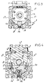
- the linear guide module comprises a body (1) made of aluminum obtained by spinning.
- This body hollow internally, has, on its upper face (1-1), a horizontal slot or opening allowing the positioning of a sealing and protective strip (2) and the passage of the upper part of the table or strut (3) capable of receiving parts or accessories.
- the body (1) has on its lateral sides (1-3, 1-4) and its rectilinear bottom face (1-5) profiled notches (1-6) allowing the positioning of clamping and fixing means relative to a support plan.
- the body has, in its lower base, profiled lightening openings (1-7).
- the lower base is horizontal and uses the maximum width of the guide body as a support surface to give the body maximum inertia.
- the lower base of the body has over its entire length, a longitudinal opening in which can be positioned a connecting strip (16), this arrangement allowing in the same volume of the body to limit the reduction in inertia, retaining an undistressed lower support plane.
- the upper part of the body has edges (1-8) forming a flap defining a reduced slot for passage and positioning of a protective strip; these edges are established if necessary with a profile to ensure the maintenance and the holding of said protective strip, according to the characteristics of the chosen sealing device.
- the lateral ends of the body are arranged with front and rear flanges (4 and 5) which are fixed to said body by any suitable connection means.
- the flanges are arranged and profiled to close and close off the ends of the body (1) and are fixed to the latter by connecting screws.
- they are arranged in their central part to allow the guiding and rotation of a guiding axis (6) disposed over the entire length of the body.
- the front flange (4) has an internal shoulder (4-1) allowing the positioning of bearings (7) for rotation of the guide axis.
- the bearing by its fixed part is secured to the body by connecting screw (8), while the guide pin projects outside the body and is arranged to receive a locking nut (6-1) abutting against the bearing .
- the front end (6-2) of the guide pin overflows to allow it to be driven by any suitable control means.
- the rear flange (5) is also arranged with a central bore (5-1) for engagement of the other end (6-3) of the guide axis.
- the bearings (4 and 5) present other arrangements which will be described elsewhere.
- the linear module allows the controlled longitudinal movement of the trainer (3) which is capable of being moved along the body in reciprocating motion according to a predetermined cycle.
- This stretcher has two distinct parts, namely a profiled base (3-1) capable of surrounding the guide axis (6), and coming to bear and center on one or more transport trolleys (10) which move on a guide rail (11) disposed in the bottom of the body (1).
- This stretcher is arranged, in addition, in its upper part (3-2) in the extension of the previous one with an adapted profile defining a constriction (3.8) then opening out to the outside of the body to form a support table for parts and accessories.
- the stringer has on either side of its median plane two slots or notches (3.9) engaging around the profile of the flaps (1.8) upper body.
- the strut is also arranged on its front face with a bore (3-3) allowing the positioning of a nut ring (13) mounted on the guide axis; said nut ring has an outer flange or flange (13-1) capable of coming into front abutment and being fixed against the strut.
- the rotation of the translation axis on itself thus causes the controlled linear displacement of the nut ring and the thrust of the strut.
- damping elements (34) are mounted on the screw and constitute end-of-stroke means of the stringer.
- the strut has in its base a central recess (3-4) open capable of surrounding the axis of translation by opening on the lower external face of the stretcher to form a cavity (3-5) , likely to position and center the or the carriages (10).
- the stretcher also has on its lower base profiles or lugs (3-6) allowing the insertion of connection and attachment means (14) of the fixing screw type for coupling it to the carriage (s).
- the carriage (s) are established in the form of a body coming to bear and guide on a rail (11) disposed along the body of the module, and in a longitudinal recess (11.3) formed for this purpose, and the ends of which (11-1 ) (11-2) are engaged and supported in profiled openings (4-2) (5-2) formed on the front and rear transverse flanges of the module.
- a screw-type connecting means (15) ensures the positioning of the rail and the underlying strip (16).
- the carriages two in this case, in number depending on the load applied to the stretcher, are arranged at their base with an obviously U-shaped (10-1) to adapt and overlap the rail, while they have on their upper part a support base (10-2) rectilinear and horizontal on which is supported, the lower base of the gaiter.
- the support base (3-5) of the stretcher has a peripheral border (3-7) allowing its centering and fitting relative to the carriage (s) . These are located in the lower part of the module body.
- This arrangement of the strut relative to the carriage makes it possible to obtain a precise and non-random positioning.
- the walls of this cavity allow the lateral forces to be transmitted independently of the connection and attachment means on the carriages.
- the design as described of the module thus makes it possible to give it great inertia and to ensure a total protection of the external environment of the various mechanisms and means of drive and movement of the stretcher
- the body of the linear module is more compact.
- the sealing means capable of protecting and covering the upper longitudinal slot of the module body can be of any type.
- a protective strip may or may not be attached to the upper edges of the body, crossing the longitudinal stretcher and in any suitable manner.
- the stringer is arranged in its upper part with a profiled opening for passage and guide of the strip.
- a sealing device constituted by bellows may be used in any known manner.
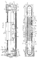
- the body of the linear module is established without modification of the above characteristics to allow the insertion of another mechanism for movement of the gib, as illustrated in FIGS. 5 to 8.
- This mechanism is a belt assembly. It is specified that the similar parts in the two implementations keep the same references.
- the modular body is strictly of the same design as before and is arranged in particular with a horizontal base base (1.5), upper flaps (1.8) horizontal leaving a passage passage and possible sealing means.
- the bottom part of the body is arranged to receive a rail (11) and a strip (16) with a connecting means (15) of the aforementioned type.
- Carriages (10) are arranged at their U-shaped base (10.1) to adapt and overlap the rail (11).
- the trainer (17) is of almost similar design to the trainer (3) with the difference that it is arranged to cooperate and be driven by a belt (18) arranged in a horizontal plane with vertical strands, and not by a screw of the type of that previously described.
- the stringer (17) has in its part underlying the upper edge of the body a mass (17.1) having two faces (17.2) (17.3) parallel and rectilinear in their median area to be opposite the passage of the strands (18.1 - 18.2) of the drive belt. Their ends can be untwisted to facilitate the passage of the belt.
- Said mass is extended by its lower part by a base (17.4) bearing and centering on the carriages (10) of the aforementioned type.
- Means (19) of the bolt type provide the connection between the stretcher and the carriages.
- the general shape of the stretcher has an I-shaped profile and in particular and advantageously for its belt drive.
- the strands of the belt (18) lie in a vertical plane and are integrated inside the body of the module while being perfectly protected from the outside, and without any particular arrangement of the body of the module.
- the body (1) of the linear module receives at its transverse ends, two plates forming end pieces (20 - 21) which are fixed to the body by bolting (22) and the like.
- Each end piece (20 - 21) is arranged with internal openings and collars to receive respectively a driving pin or drum (23) and driven pin or drum (24) mounted on bearings (25), locking means (26) ensuring fixing and maintaining the assembly.
- the end piece (20) is arranged with an upper opening (20.1) for the passage of the leading axis (23) with a view to its coupling with a drive motor means.
- a cover (27) is arranged in the lower opening (20.2) and allows access to the axis locking means.
- the other end piece (21) is also arranged in its lower part with an opening (21.1) for the reception of a cover (27).
- the upper part (21.2) of the end piece is closed and serves as a housing for rolling means (25).
- a belt is arranged which crosses the length of the body of the linear module, facing the rectilinear and parallel faces (17.2 - 17.3) of the strut.
- the latter can be arranged over all or part of its length and on its internal face with a notch capable of cooperating with a complementary notched part formed on the driving axis (23).
- the driven axis can optionally be notched also depending on the applications given to the linear module.
- the axes (23 and 24) are also in a fixed position.
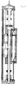
- the strap (18) is attached and fixed by its ends (18.3 - 18.4) facing one of the faces (17.2 or 17.3) of the stretcher.
- This fixing takes place for example in the following manner in order to ensure a possible tensioning of the belt.
- Clamp elements (28 - 29)) are attached to the wall of the stringer and are fixed to the latter by bolting (30) or the like.
- the internal face (28.1 - 29.1) of the gripper part can be notched and cooperate with a complementary notching partially established on the corresponding face of the strut. It is thus possible by bringing the clamps together with respect to their means of attachment to the stretcher, ensuring a more or less strong tensioning of the belt.
- these clamps are arranged internally with openings (28.2 - 29.2) in which the ends of said belt are engaged, clamping means ensuring their hold.
- FIG. 7 illustrates the means of tightening the belt by bringing its ends closer together. More in particular, the clamps (28 and 29) have raised edges (28.3 - 29.3) at the end arranged with threaded openings for the passage of a tensioning screw (31).
- Sealing means for covering the upper slot of the body of the linear module are then added in any suitable manner.
- These sealing means may be bellows, protective strips which may or may not fit in the slot formed between the upper edges forming flaps of the body.
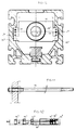
- FIGS. 9 to 12 of the drawings an arrangement complementary to the arrangement of the linear guide module which can be used whatever the means of movement and drive of the gib.
- the body of the module has internally, on its opposite lateral edges, a recess (1.9) allowing the introduction, positioning and guidance of one or more pieces (32) forming flanges arranged transversely in the module .
- These flanges can be arranged, in their central part, with an opening (32.1) for the passage of the guide pin (6) described as the first means of movement of the gib.
- These flanges are arranged at their ends (32.2) with bearing surfaces engaging and centering in said recesses.
- These flanges are mounted guided on a plurality of tie rods (33) in a number corresponding to the number of flanges associated with the strut. More particularly, FIG.
- the strut has thus illustrated the strut with the various flanges arranged on either side.
- the flanges (32.3 - 32.4 - 32.5 - 32.6 - 32.7 - 32.8) are associated two by two by the tie rods (33.1 - 33.2 - 33.3). These cross freely.
- the connection of the associated flanges and tie rods is obtained by bolting or the like. It is thus understood that when moving the strut in one direction or another, it causes the successive displacement of the different flanges on one side themselves ensuring the movement and drive of the flanges arranged on the other side of the stretcher. This additional arrangement completes the guidance of the assembly and provides support for the screw.
- the number of flanges (32) can vary according to the needs and the length of the linear module, and therefore therefore, depending on the length of the screw.
- the number of flanges is also a function of the diameter of the screw and its speed of rotation. The originality of this characteristic thus resides in the particular arrangement of the interior body of the module with the aforementioned recesses (1.9) to allow the positioning of the abovementioned flanges, thus ensuring additional guidance in the profile of the body of the linear module.
- the flanges have openings for positioning and fixing the tie rods in an inverted and alternating position.
Landscapes
- Engineering & Computer Science (AREA)
- Mechanical Engineering (AREA)
- Rehabilitation Tools (AREA)
- Forklifts And Lifting Vehicles (AREA)
- Transmission Devices (AREA)
- Bearings For Parts Moving Linearly (AREA)
- Structure Of Belt Conveyors (AREA)
- Specific Sealing Or Ventilating Devices For Doors And Windows (AREA)
- Manipulator (AREA)
Applications Claiming Priority (2)
| Application Number | Priority Date | Filing Date | Title |
|---|---|---|---|
| FR9003985A FR2659890A1 (fr) | 1990-03-22 | 1990-03-22 | Module lineaire de guidage pour la translation et la manutention de toutes pieces et accessoires. |
| FR9003985 | 1990-03-22 |
Publications (2)
| Publication Number | Publication Date |
|---|---|
| EP0448485A1 EP0448485A1 (fr) | 1991-09-25 |
| EP0448485B1 true EP0448485B1 (fr) | 1994-11-30 |
Family
ID=9395216
Family Applications (1)
| Application Number | Title | Priority Date | Filing Date |
|---|---|---|---|
| EP91420094A Expired - Lifetime EP0448485B1 (fr) | 1990-03-22 | 1991-03-20 | Module linéaire de guidage pour la translation et la manutention de toutes pièces et accessoires |
Country Status (7)
| Country | Link |
|---|---|
| US (1) | US5131125A (enExample) |
| EP (1) | EP0448485B1 (enExample) |
| AT (1) | ATE114526T1 (enExample) |
| CA (1) | CA2038216A1 (enExample) |
| DE (1) | DE69105320T2 (enExample) |
| FR (1) | FR2659890A1 (enExample) |
| PT (1) | PT97126A (enExample) |
Cited By (2)
| Publication number | Priority date | Publication date | Assignee | Title |
|---|---|---|---|---|
| CN107725588A (zh) * | 2017-09-28 | 2018-02-23 | 上海理工大学 | 轻量化可拆卸式折叠直线传动导轨 |
| CN111409112A (zh) * | 2020-05-08 | 2020-07-14 | 中国航空制造技术研究院 | 一种用于直线位移坐标的导轨防护机构 |
Families Citing this family (42)
| Publication number | Priority date | Publication date | Assignee | Title |
|---|---|---|---|---|
| DE4032820C1 (enExample) * | 1990-10-16 | 1991-11-07 | Deutsche Star Gmbh, 8720 Schweinfurt, De | |
| FR2684034B1 (fr) * | 1991-11-26 | 1996-03-29 | Coron Jean Paul | Module lineaire de guidage pour la translation et la manutention de toutes pieces et accessoires. |
| EP0585429B1 (de) * | 1992-03-19 | 1996-05-08 | Maschinenfabrik Rieter Ag | Vorrichtung zum schleifen von garnituren beispielsweise einer karden- oder reinigungstrommel |
| JP2578150Y2 (ja) * | 1992-10-13 | 1998-08-06 | 日本トムソン株式会社 | 直動転がり案内ユニット |
| USD344964S (en) | 1992-10-14 | 1994-03-08 | Nippon Bearing Co., Ltd. | Ball bearing for rectilinear sliding |
| USD351848S (en) | 1993-01-13 | 1994-10-25 | Nippon Bearing Co., Ltd. | Ball bearing for rectilinear sliding |
| US6337456B1 (en) * | 1998-12-16 | 2002-01-08 | Dengensha Manufacturing Company Limited | Welding machine and method for assembling same |
| US6223611B1 (en) * | 1999-05-03 | 2001-05-01 | Force Control Industries, Inc. | Belt transfer system |
| KR20030090943A (ko) * | 2002-05-24 | 2003-12-01 | 아이램테크(주) | 반도체공정 로봇 직선 주행부의 실링구조 |
| DE10316427B4 (de) * | 2003-04-08 | 2006-05-04 | Hermann Oesterle | Ausricht- und Justiereinrichtung sowie Werkzeugmaschine mit einer Ausricht- und Justiervorrichtung |
| DE10318777A1 (de) * | 2003-04-25 | 2004-11-11 | Ina-Schaeffler Kg | Linearführungseinheit |
| DE10318776A1 (de) * | 2003-04-25 | 2004-11-11 | Ina-Schaeffler Kg | Linearführungseinheit |
| WO2006017953A1 (de) * | 2004-08-18 | 2006-02-23 | Soudronic Ag | Verfahren und vorrichtung zum fördern von zu bearbeitenden gegenständen |
| ATE385979T1 (de) * | 2005-11-04 | 2008-03-15 | Thierry Verroeye | Vorrichtung und verfahren zur handhabung, insbesondere zum stapeln, von profilteile |
| JP2007270860A (ja) * | 2006-03-30 | 2007-10-18 | Smc Corp | 電動アクチュエータ |
| DE202007004694U1 (de) * | 2007-03-30 | 2008-08-14 | Robert Bosch Gmbh | Lineareinheit |
| US8474599B2 (en) * | 2010-02-01 | 2013-07-02 | Midaco Corporation | Drive for pallet changer |
| ITMO20120319A1 (it) * | 2012-12-21 | 2014-06-22 | Edit Di Roggiani Massimo | Dispositivo di guida per un oggetto. |
| ITMO20130079A1 (it) * | 2013-03-26 | 2014-09-27 | Edit Di Roggiani Massimo | "dispositivo di tensionamento per una cinghia di trasmissione." |
| CN105467990A (zh) * | 2014-09-12 | 2016-04-06 | 鸿富锦精密工业(深圳)有限公司 | 单轴机器人 |
| DE102016107396A1 (de) * | 2016-04-21 | 2017-10-26 | Festo Ag & Co. Kg | Schlitten zum Führen an einer Linearführungseinheit |
| USD800190S1 (en) * | 2016-05-25 | 2017-10-17 | Zapadoc̄Eská Univerzita V Plzni | Linear guideway |
| USD798925S1 (en) * | 2016-05-25 | 2017-10-03 | Zapadoceka Univerzita V Plzni | Linear guideway |
| USD800191S1 (en) * | 2016-05-25 | 2017-10-17 | Zapadoceska Univerzita V Plzni | Linear guideway with a drive |
| USD800809S1 (en) * | 2016-05-25 | 2017-10-24 | Zapadoceska Univerzita V Plzni | Linear guideway |
| USD800189S1 (en) * | 2016-05-25 | 2017-10-17 | Zapadoceska Univerzita V Plzni | Linear guideway |
| USD798926S1 (en) * | 2016-05-25 | 2017-10-03 | Zapadoceska Univerzita V Plzni | Linear guideway |
| USD800192S1 (en) * | 2016-05-25 | 2017-10-17 | ZAPADO{grave over (C)}ESKA UNIVERZITA V PLZNI | Linear guideway |
| USD800925S1 (en) * | 2016-05-25 | 2017-10-24 | Zapadoceska Univerzita V Plzni | Linear guideway |
| USD800812S1 (en) * | 2016-05-25 | 2017-10-24 | ZA{grave over (P)}ADOC̅ESKA UNIVERZITA V PLZNI | Linear guideway |
| USD800811S1 (en) * | 2016-05-25 | 2017-10-24 | Zapadoceska Univerzita V Plzni | Linear guideway |
| USD800810S1 (en) * | 2016-05-25 | 2017-10-24 | Zapadoceska Univerzita V Plzni | Linear guideway |
| TWI685623B (zh) * | 2018-02-08 | 2020-02-21 | 上銀科技股份有限公司 | 用於線性模組之防塵裝置 |
| CN110153733A (zh) * | 2019-06-24 | 2019-08-23 | 重庆宏钢数控机床有限公司 | 多阶导轨专用机床 |
| CN110153732A (zh) * | 2019-06-24 | 2019-08-23 | 重庆宏钢数控机床有限公司 | 一种专用机床床身 |
| CN110549151B (zh) * | 2019-09-16 | 2020-07-28 | 聊城大学 | 一种履带导轨驱动微量进给伺服系统及同步控制方法 |
| WO2021089094A1 (en) * | 2019-11-05 | 2021-05-14 | Wahlberg Holding Aps | A linear manipulator for a programmable stage installation, a body for a linear manipulator and use of a linear manipulator |
| CN112658772B (zh) * | 2021-03-22 | 2021-06-11 | 思特博恩(常州)新材料科技有限公司 | 一种机床床身用进给装置及其控制方法 |
| US12275113B2 (en) * | 2021-06-15 | 2025-04-15 | Midaco Corporation | Method and apparatus for delivering workpieces to and from a machine table |
| CN114151443A (zh) * | 2021-12-23 | 2022-03-08 | 黑马瓦尔特防护技术(连云港)有限公司 | 新型导轨结构以及具有新型导轨结构的防护系统 |
| DE102022125217A1 (de) * | 2022-09-29 | 2024-04-04 | Ewellix AB | Linearmodul |
| FR3148732B1 (fr) | 2023-05-17 | 2025-05-02 | Coron Jean Paul | Axe linéaire étanche |
Family Cites Families (10)
| Publication number | Priority date | Publication date | Assignee | Title |
|---|---|---|---|---|
| US2522695A (en) * | 1946-11-12 | 1950-09-19 | Gray & Co G A | Machine tool guide |
| US3405600A (en) * | 1966-02-09 | 1968-10-15 | Moog Inc | Numerical control positioning apparatus |
| DE3040711A1 (de) * | 1980-10-29 | 1982-06-03 | Hugo Isert | Fuehrungssystem fuer lineare bewegungen |
| SE439968B (sv) * | 1982-10-19 | 1985-07-08 | Ulf Kenneth Folke Fasth | Stelldon |
| DE3336496A1 (de) * | 1983-10-07 | 1985-04-25 | Hauser Elektronik GmbH, 7600 Offenburg | Linearantrieb |
| FR2618361A1 (fr) * | 1987-07-22 | 1989-01-27 | Somex Sa | Machine-outil comportant un bati et un chariot de translation |
| DE3734922A1 (de) * | 1987-10-15 | 1989-04-27 | Bahr & Co Gmbh | Auf einem profilrohr gefuehrte und in dessen laengsrichtung hin- und herbewegbare verstelleinrichtung |
| DE8715922U1 (de) * | 1987-12-02 | 1988-01-21 | Neff Gewindespindeln GmbH, 7035 Waldenbuch | Mechanische Lineareinheit |
| DE3804117A1 (de) * | 1988-02-11 | 1989-08-24 | Neff Gewindespindeln | Mechanische lineareinheit |
| DE3815595A1 (de) * | 1988-05-06 | 1989-11-23 | Star Gmbh | Linearfuehrungseinheit |
-
1990
- 1990-03-22 FR FR9003985A patent/FR2659890A1/fr active Granted
-
1991
- 1991-03-19 CA CA002038216A patent/CA2038216A1/fr not_active Abandoned
- 1991-03-20 AT AT91420094T patent/ATE114526T1/de not_active IP Right Cessation
- 1991-03-20 EP EP91420094A patent/EP0448485B1/fr not_active Expired - Lifetime
- 1991-03-20 DE DE69105320T patent/DE69105320T2/de not_active Expired - Fee Related
- 1991-03-21 US US07/673,226 patent/US5131125A/en not_active Expired - Fee Related
- 1991-03-22 PT PT97126A patent/PT97126A/pt not_active Application Discontinuation
Cited By (2)
| Publication number | Priority date | Publication date | Assignee | Title |
|---|---|---|---|---|
| CN107725588A (zh) * | 2017-09-28 | 2018-02-23 | 上海理工大学 | 轻量化可拆卸式折叠直线传动导轨 |
| CN111409112A (zh) * | 2020-05-08 | 2020-07-14 | 中国航空制造技术研究院 | 一种用于直线位移坐标的导轨防护机构 |
Also Published As
| Publication number | Publication date |
|---|---|
| FR2659890A1 (fr) | 1991-09-27 |
| DE69105320D1 (de) | 1995-01-12 |
| DE69105320T2 (de) | 1995-07-13 |
| FR2659890B1 (enExample) | 1995-05-12 |
| US5131125A (en) | 1992-07-21 |
| ATE114526T1 (de) | 1994-12-15 |
| EP0448485A1 (fr) | 1991-09-25 |
| PT97126A (pt) | 1993-04-30 |
| CA2038216A1 (fr) | 1991-09-23 |
Similar Documents
| Publication | Publication Date | Title |
|---|---|---|
| EP0448485B1 (fr) | Module linéaire de guidage pour la translation et la manutention de toutes pièces et accessoires | |
| CA2038564A1 (fr) | Dispositif d'etancheite pour un module lineaire de guidage pour la translation et la manutention de toutes pieces et accessoires | |
| FR2773789A1 (fr) | Construction de convoyeur | |
| EP0634986B1 (fr) | Systeme de convoyage en translation/rotation d'un element support | |
| EP1200234A1 (fr) | Prehenseur modulaire | |
| FR2671752A1 (fr) | Systeme actionneur de pinces pour un cadre de fixation supporte par un convoyeur. | |
| EP0929486B1 (fr) | Dispositif de convoyage d'objets munis d'un goulot ou similaire tels que par exemple des bouteilles, flacons ou autres et dispositif de chargement de tels objets concus pour ledit dispositif de convoyage | |
| EP1132234B1 (fr) | Module de porte de véhicule avec panneau porteur intégré | |
| BE1000911A5 (fr) | Transporteur tridimensionnel a palettes. | |
| WO2012076330A1 (fr) | Goulotte de reception d'elements allonges, son procede de montage et ensemble comprenant un support et une telle goulotte | |
| WO2002060641A1 (fr) | Corps profile monobloc destine a inclure un organe moteur et module lineaire realise a partir d"un tel corps | |
| EP0465281A1 (fr) | Porte coulissante et son mécanisme de commande | |
| FR2675068A1 (fr) | Mecanisme de manutention compose d'elements modulaires. | |
| FR2836432A1 (fr) | Dispositif de fixation d'un accessoire sur un support | |
| EP0576378A1 (fr) | Module linéaire de guidage pour la translation et la manutention de toutes pièces et accessoires | |
| FR2956148A1 (fr) | Actionneur a bras pour vantail | |
| EP4214458B1 (fr) | Dispositif de chargement d'un obus dans la chambre d'une arme | |
| EP0119890B1 (fr) | Appareil pour la coupe en biseau d'une pièce | |
| FR3110103A1 (fr) | dispositif de saisie d’outil | |
| EP0992316B1 (fr) | Dispositif manuel de correction du positionnement du corps d'une électro-broche par rapport à son support | |
| FR2480166A1 (fr) | Dispositif pour maintenir des cles dans une machine a reproduire les cles | |
| EP1590273A1 (fr) | Palette pour cha ne de convoyeur-------------------------- | |
| FR2823029A1 (fr) | Pince motorisee pour le bridage d'elements allonges | |
| FR2700321A1 (fr) | Dispositif de préhension et de transport d'un cylindre de révolution posé horizontalement sur un support. | |
| EP1186837B1 (fr) | Dispositif de fixation murale d'un radiateur de chauffage et procédé de fixation d'un tel radiateur |
Legal Events
| Date | Code | Title | Description |
|---|---|---|---|
| PUAI | Public reference made under article 153(3) epc to a published international application that has entered the european phase |
Free format text: ORIGINAL CODE: 0009012 |
|
| AK | Designated contracting states |
Kind code of ref document: A1 Designated state(s): AT BE CH DE DK ES FR GB GR IT LI LU NL SE |
|
| 17P | Request for examination filed |
Effective date: 19911216 |
|
| 17Q | First examination report despatched |
Effective date: 19930209 |
|
| RAP1 | Party data changed (applicant data changed or rights of an application transferred) |
Owner name: KINETIC TECHNOLOGIES |
|
| GRAA | (expected) grant |
Free format text: ORIGINAL CODE: 0009210 |
|
| AK | Designated contracting states |
Kind code of ref document: B1 Designated state(s): AT BE CH DE DK ES FR GB GR IT LI LU NL SE |
|
| PG25 | Lapsed in a contracting state [announced via postgrant information from national office to epo] |
Ref country code: NL Effective date: 19941130 Ref country code: GR Free format text: LAPSE BECAUSE OF FAILURE TO SUBMIT A TRANSLATION OF THE DESCRIPTION OR TO PAY THE FEE WITHIN THE PRESCRIBED TIME-LIMIT Effective date: 19941130 Ref country code: GB Effective date: 19941130 Ref country code: ES Free format text: THE PATENT HAS BEEN ANNULLED BY A DECISION OF A NATIONAL AUTHORITY Effective date: 19941130 Ref country code: DK Effective date: 19941130 Ref country code: AT Effective date: 19941130 |
|
| REF | Corresponds to: |
Ref document number: 114526 Country of ref document: AT Date of ref document: 19941215 Kind code of ref document: T |
|
| REF | Corresponds to: |
Ref document number: 69105320 Country of ref document: DE Date of ref document: 19950112 |
|
| ITF | It: translation for a ep patent filed | ||
| PG25 | Lapsed in a contracting state [announced via postgrant information from national office to epo] |
Ref country code: SE Effective date: 19950228 |
|
| PGFP | Annual fee paid to national office [announced via postgrant information from national office to epo] |
Ref country code: FR Payment date: 19950324 Year of fee payment: 5 Ref country code: DE Payment date: 19950324 Year of fee payment: 5 |
|
| PG25 | Lapsed in a contracting state [announced via postgrant information from national office to epo] |
Ref country code: LU Free format text: LAPSE BECAUSE OF NON-PAYMENT OF DUE FEES Effective date: 19950331 Ref country code: LI Effective date: 19950331 Ref country code: CH Effective date: 19950331 Ref country code: BE Effective date: 19950331 |
|
| NLV1 | Nl: lapsed or annulled due to failure to fulfill the requirements of art. 29p and 29m of the patents act | ||
| GBV | Gb: ep patent (uk) treated as always having been void in accordance with gb section 77(7)/1977 [no translation filed] |
Effective date: 19941130 |
|
| BERE | Be: lapsed |
Owner name: KINETIC TECHNOLOGIES Effective date: 19950331 |
|
| PLBE | No opposition filed within time limit |
Free format text: ORIGINAL CODE: 0009261 |
|
| STAA | Information on the status of an ep patent application or granted ep patent |
Free format text: STATUS: NO OPPOSITION FILED WITHIN TIME LIMIT |
|
| 26N | No opposition filed | ||
| REG | Reference to a national code |
Ref country code: CH Ref legal event code: PL |
|
| PG25 | Lapsed in a contracting state [announced via postgrant information from national office to epo] |
Ref country code: FR Effective date: 19961129 |
|
| PG25 | Lapsed in a contracting state [announced via postgrant information from national office to epo] |
Ref country code: DE Effective date: 19961203 |
|
| REG | Reference to a national code |
Ref country code: FR Ref legal event code: ST |
|
| PG25 | Lapsed in a contracting state [announced via postgrant information from national office to epo] |
Ref country code: IT Free format text: LAPSE BECAUSE OF NON-PAYMENT OF DUE FEES;WARNING: LAPSES OF ITALIAN PATENTS WITH EFFECTIVE DATE BEFORE 2007 MAY HAVE OCCURRED AT ANY TIME BEFORE 2007. THE CORRECT EFFECTIVE DATE MAY BE DIFFERENT FROM THE ONE RECORDED. Effective date: 20050320 |