EP0447975A1 - Système d'allumage pour moteur à combustion - Google Patents
Système d'allumage pour moteur à combustion Download PDFInfo
- Publication number
- EP0447975A1 EP0447975A1 EP91104005A EP91104005A EP0447975A1 EP 0447975 A1 EP0447975 A1 EP 0447975A1 EP 91104005 A EP91104005 A EP 91104005A EP 91104005 A EP91104005 A EP 91104005A EP 0447975 A1 EP0447975 A1 EP 0447975A1
- Authority
- EP
- European Patent Office
- Prior art keywords
- transistor
- current
- circuit
- potential difference
- coil
- Prior art date
- Legal status (The legal status is an assumption and is not a legal conclusion. Google has not performed a legal analysis and makes no representation as to the accuracy of the status listed.)
- Ceased
Links
Images

Classifications
-
- F—MECHANICAL ENGINEERING; LIGHTING; HEATING; WEAPONS; BLASTING
- F02—COMBUSTION ENGINES; HOT-GAS OR COMBUSTION-PRODUCT ENGINE PLANTS
- F02P—IGNITION, OTHER THAN COMPRESSION IGNITION, FOR INTERNAL-COMBUSTION ENGINES; TESTING OF IGNITION TIMING IN COMPRESSION-IGNITION ENGINES
- F02P3/00—Other installations
- F02P3/02—Other installations having inductive energy storage, e.g. arrangements of induction coils
- F02P3/04—Layout of circuits
- F02P3/05—Layout of circuits for control of the magnitude of the current in the ignition coil
- F02P3/051—Opening or closing the primary coil circuit with semiconductor devices
- F02P3/053—Opening or closing the primary coil circuit with semiconductor devices using digital techniques
Definitions
- the present invention relates to an ignition system for an internal combustion engine.
- the subject of the invention is an ignition system comprising: at least one spark plug, at least one ignition coil whose secondary winding is connected or connectible to the at least one plug, a power transistor whose output path is in series with the primary winding of the coil between the two terminals of a direct-current voltage supply, a driver circuit for the transistor, means for detecting the potential difference between the terminals of the output path of the transistor, and control circuit means connected to the driver circuit for switching the transistor gradually from the cut-off condition to the saturated condition in a controlled manner in dependence on the potential difference in order to cause current to flow in the primary winding of the coil, the control means including electronic processing means for generating a logic control signal in which, to generate a spark, there is a first change of level to start the switching of the transistor to the saturated condition and the flow of current in the primary winding of the coil, and a second change of level to cut off the transistor and trigger the spark.
- the power transistor associated with the plug in order to generate a spark in a plug, is switched gradually from the cut-off condition to the saturated conditon in a controlled manner in dependence on the voltage detected between its collector and its emitter, that is, between its drain and its source, in order to prevent overvoltages in the secondary winding of the associated ignition coil.
- a sudden and uncontrolled switching of the transistor from the cut-off condition to the saturated condition would cause a voltage peak to appear in the secondary winding of the ignition coil, followed by a damped oscillation attributable to the intrinsic stray capacitance of the system. This peak might trigger a spurious, that is, an undesired, spark and, in order to avoid this, a diode suitable for high voltages, which is quite expensive, is usually put in series with the plug.
- the object of the present invention is to provide an ignition system of the type specified at the beginning which enables a more precise and effective progressive control of the switching of the transistor between the cut-off and saturated conditions.
- control circuit means also include: a pulse generator for generating pulses at a frequency greater than the reciprocal of the minimum time interval between the first and second changes in the control logic signal, a comparator for supplying a control signal when the potential difference between the terminals of the output path of the transistor falls to a predetermined threshold value during the switch from the cut-off condition to the saturated condition, and a selection logic circuit having first and second inputs connected to the processing means and to the pulse generator respectively, a control input connected to the input of the comparator, and an output connected to the driver circuit for the transistor, the selection logic circuit being arranged to transmit to the driver circuit:
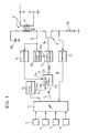
- the ignition system shown in Figure 1 includes a sensor 1 for outputting a signal whose frequency is indicative of the rate of rotation of the shaft of the internal combustion engine. From the signal supplied by that sensor, which may comprise, for example, a toothed wheel associated with a magnetic pick-up, it is also possible - in known manner - to derive data on the angular position of the engine shaft and to determine the moments at which the spark must be struck in the various cylinders.
- a sensor 1 for outputting a signal whose frequency is indicative of the rate of rotation of the shaft of the internal combustion engine. From the signal supplied by that sensor, which may comprise, for example, a toothed wheel associated with a magnetic pick-up, it is also possible - in known manner - to derive data on the angular position of the engine shaft and to determine the moments at which the spark must be struck in the various cylinders.
- Further sensors indicated 2 to 4, output electrical signals indicative of the vacuum in the intake manifold of the engine, the intake-air temperature, and the temperature of the engine cooling water.
- the sensors 1 to 4 are connected to an electronic control unit 5 with a microprocessor of known type with memory devices.
- the drain-source path of a MOSFET power transistor, indicated 6 is connected in series with the primary winding 7 of an ignition coil 8 between the terminals of a direct-current voltage supply V B (the motor vehicle's battery).
- the coil 8 includes a secondary winding 9 connected to a spark plug SP.
- the output of a pulse generator 10 is connected to a first input 11a of a selection logic circuit 11 which has a second input 11b connected to an output of the electronic control unit 5.
- the selection circuit has a control input 11c connected to the output of a comparator 12. This comparator has an input connected to the drain of the transistor 6.
- the logic selection circuit 11 is arranged selectively to transmit from its output the signal coming from the electronic unit 5 or that coming from the pulse generator 10, according to the signal applied to its control input 11c.
- the output of the selection logic circuit 11 is connected to the control input of a current generator 13 whose output is connected to the gate of the transistor 6.
- the current generator 13 applies a current signal of constant intensity to the gate of the transistor 6 when the signal supplied to it by the selection logic circuit is at a "high” level, whilst it does not generate a current when that signal is at a “low” level.
- electronic control unit 5 is arranged, in known manner, to calculate the ignition advance on the basis of the signals provided by the sensors 1 to 4.
- the unit 5 is particularly arranged, also in known manner, to output a logic control signal, indicated C in Figures 1 and 2.
- the signal C first changes from the "low” level to the "high” level at an instant t0 and then stays at the high level until a subsequent instant t1 when the spark is to be produced.
- the time interval between the two changes in the level of the signal C varies according to the rate of rotation of the engine.
- the pulse generator 10 is arranged to generate pulses at a frequency greater than the reciprocal of the minimum time interval between the aforesaid two changes in the control logic signal emitted by the control unit 5.
- the transistor 6 is cut off and the comparator 12 keeps the selection logic circuit 11 in the condition in which it transfers the signal from the unit 5 to the input of the current generator.
- the drain potential V D of the transistor 6 is kept at a high level substantially equal to the voltage V B of the supply minus the small voltage drop across the primary winding 7 of the ignition coil 8.
- the current generator is activated in correspondence with each pulse of the signal P to cause a gradual stepped increase in the gate potential V G of the transistor 6.
- the drain potontial V D of the transistor is reduced very gradually in steps in a corresponding manner, as shown in Figure 2. This gradual variation of V D effectively prevents overvoltages in the secondary winding of the ignition coil 8 and thus prevents the triggering of spurious sparks.
- this signal has the advantage that it is continuous during the initial stage of the switching of the transistor 6. This enables the transistor to be brought quickly to the threshold at which it switches from the cut-off condition to the conducting condition.
- the speed at which this stage is reached is very important in view of the fact that the time usable to bring the current in the primary winding of the ignition coil to a level sufficient to ensure the striking of the spark is extremely short, particularly at high rates of revolution of the internal combustion engine.
- V D can be controlled more precisely if the pulse generator 10 is of the type whose frequency or duty cycle can be varied in dependence on the time period (t3 - t0) which can be "monitored” by the unit 5 and/or on the time period (t4 - t3).
- the variability of the frequency or the duty cycle in dependence on the time period (t3 - t0) counteracts the effects of the spread (inequality, inconsistency) of the characteristics of the power transistors used.
- the variability of the frequency or the duty cycle in dependence on (t4 - t3) counteracts the spread of the characteristics of the ignition coils and, in particular, of their primary windings.
- the current generator 13 may be formed so as to output a current of constant intensity which can be varied in dependence on a control signal applied to an input indicated 13a in Figure 1.
- the circuit 20 can be formed in a manner obvious to an expert in the art, for example, with the use of differentiating and comparison circuits.
- a sensing resistor 19 may be provided between the source of the transistor 6 and earth, the voltage developed between its terminals in operation being proportional to the intensity of the current I.
- the resistor is conveniently connected to the input of a threshold comparator 21 which compares the voltage across the resistor with predetermined reference values and supplies the electronic control unit 5 with a signal having, for example, the curve indicated B in Figure 2, with a change in level at the instant t4 when the current I exceeds a predetermined threshold I0.
- the control unit 5 can then generate its own control signals C on the basis of the time taken for the current I to reach the value I0 so as to ensure that an adequate current level is reached in the primary winding 7 to enable the spark to be struck even if the voltage V B is below its nominal value.
- the power transistor could be an IGBT (insulated gate bipolar transistor) instead of a MOSFET.
Landscapes
- Engineering & Computer Science (AREA)
- Chemical & Material Sciences (AREA)
- Combustion & Propulsion (AREA)
- Mechanical Engineering (AREA)
- General Engineering & Computer Science (AREA)
- Ignition Installations For Internal Combustion Engines (AREA)
- Combustion Methods Of Internal-Combustion Engines (AREA)
Applications Claiming Priority (2)
| Application Number | Priority Date | Filing Date | Title |
|---|---|---|---|
| IT6719990 | 1990-03-19 | ||
| IT67199A IT1240136B (it) | 1990-03-19 | 1990-03-19 | Sistema di accensione per un motore a combustione interna |
Publications (1)
| Publication Number | Publication Date |
|---|---|
| EP0447975A1 true EP0447975A1 (fr) | 1991-09-25 |
Family
ID=11300427
Family Applications (1)
| Application Number | Title | Priority Date | Filing Date |
|---|---|---|---|
| EP91104005A Ceased EP0447975A1 (fr) | 1990-03-19 | 1991-03-15 | Système d'allumage pour moteur à combustion |
Country Status (5)
| Country | Link |
|---|---|
| US (1) | US5127388A (fr) |
| EP (1) | EP0447975A1 (fr) |
| JP (1) | JPH05133312A (fr) |
| BR (1) | BR9101166A (fr) |
| IT (1) | IT1240136B (fr) |
Cited By (10)
| Publication number | Priority date | Publication date | Assignee | Title |
|---|---|---|---|---|
| EP0526219A2 (fr) * | 1991-08-02 | 1993-02-03 | Motorola, Inc. | Dispositif d'allumage |
| FR2688033A1 (fr) * | 1992-02-27 | 1993-09-03 | Marelli Autronica | Dispositif d'allumage a bobine. |
| EP0559540A1 (fr) * | 1992-03-03 | 1993-09-08 | Marelli Autronica | Dispositif d'allumage électronique à bobine pour moteur à allumage commandé |
| EP0566335A2 (fr) * | 1992-04-14 | 1993-10-20 | Motorola, Inc. | Circuit d'attaque en commutation pour bobine d'allumage et méthode |
| CN1050410C (zh) * | 1995-04-04 | 2000-03-15 | 三菱电机株式会社 | 内燃机的点火装置 |
| WO2002099272A1 (fr) * | 2001-06-06 | 2002-12-12 | Siemens Aktiengesellschaft | Allumage, organe de commande et systeme d'allumage pour un moteur a combustion interne |
| WO2002099273A1 (fr) * | 2001-06-06 | 2002-12-12 | Siemens Aktiengesellschaft | Dispositif d'allumage pour moteur a combustion interne |
| FR2953256A1 (fr) * | 2009-12-01 | 2011-06-03 | Valeo Sys Controle Moteur Sas | Procede et dispositif de commande de charge d'une bobine d'allumage notamment pour un moteur a allumage commande |
| ITMI20111669A1 (it) * | 2011-09-16 | 2013-03-17 | St Microelectronics Srl | Accensione graduale in un sistema di accensione di un motore a combustione |
| CN110285002A (zh) * | 2019-06-03 | 2019-09-27 | 昆山凯迪汽车电器有限公司 | 点火驱动模块 |
Families Citing this family (19)
| Publication number | Priority date | Publication date | Assignee | Title |
|---|---|---|---|---|
| IT1238518B (it) * | 1989-11-07 | 1993-08-18 | Marelli Autronica | Circuito di interfaccia fra un microprocessore ed una pluralita' di stadi di potenza, in particolare per il pilotaggio di elettroiniettori |
| JP2796209B2 (ja) * | 1992-01-17 | 1998-09-10 | 株式会社日立製作所 | 内燃機関用電子配電点火装置 |
| DE4226248A1 (de) * | 1992-08-08 | 1994-02-10 | Bosch Gmbh Robert | Zündanlage für Brennkraftmaschinen |
| US5425348A (en) * | 1994-04-19 | 1995-06-20 | General Motors Corporation | Distributorless ignition system for an internal combustion engine |
| JPH08270534A (ja) * | 1995-03-31 | 1996-10-15 | Mitsubishi Electric Corp | 内燃機関用点火装置 |
| DE19711204C2 (de) * | 1997-03-18 | 1999-01-14 | Bosch Gmbh Robert | Schaltungsanordnung einer Zündendstufe |
| US6209408B1 (en) * | 1997-07-16 | 2001-04-03 | Grand Haven Stamped Products | Electrical sensing system for a vehicle shifter |
| US6247465B1 (en) * | 2000-02-11 | 2001-06-19 | Delphi Technologies, Inc. | System and method for preventing spark-on-make in an internal combustion engine using manifold pressure |
| US6450157B1 (en) * | 2000-07-03 | 2002-09-17 | Delphi Technologies, Inc. | Automotive ignition system with adaptable start-of-dwell ring damping |
| JP3740008B2 (ja) | 2000-10-11 | 2006-01-25 | 株式会社日立製作所 | 車載イグナイタ、絶縁ゲート半導体装置及びエンジンシステム |
| DE102004013561B4 (de) * | 2004-03-19 | 2007-02-22 | Audi Ag | Verfahren und Schaltvorrichtung zum Betreiben einer Zündspule eines Kraftfahrzeugs |
| ITMI20070139A1 (it) * | 2007-01-30 | 2008-07-31 | St Microelectronics Srl | Accensione morbida auto-adattiva di dispositivi di commutazione di potenza |
| GB0723855D0 (en) | 2007-12-06 | 2008-01-16 | Smith & Nephew | Apparatus and method for wound volume measurement |
| US8539769B2 (en) * | 2009-10-14 | 2013-09-24 | Craig N. Hansen | Internal combustion engine and supercharger |
| GB201015656D0 (en) | 2010-09-20 | 2010-10-27 | Smith & Nephew | Pressure control apparatus |
| US9067003B2 (en) | 2011-05-26 | 2015-06-30 | Kalypto Medical, Inc. | Method for providing negative pressure to a negative pressure wound therapy bandage |
| US9084845B2 (en) | 2011-11-02 | 2015-07-21 | Smith & Nephew Plc | Reduced pressure therapy apparatuses and methods of using same |
| US11274645B2 (en) * | 2019-10-15 | 2022-03-15 | Semiconductor Components Industries, Llc | Circuit and method for a kickback-limited soft shutdown of a coil |
| CN112128036A (zh) * | 2020-09-27 | 2020-12-25 | 张明芬 | 一种储磁电流软开启的电子点火控制方法、电路和系统 |
Citations (4)
| Publication number | Priority date | Publication date | Assignee | Title |
|---|---|---|---|---|
| US3938490A (en) * | 1974-07-15 | 1976-02-17 | Fairchild Camera And Instrument Corporation | Internal combustion engine ignition system for generating a constant ignition coil control signal |
| FR2330875A1 (fr) * | 1975-11-05 | 1977-06-03 | Sev Marchal | Perfectionnements apportes aux dispositifs d'allumage |
| GB2024941A (en) * | 1978-07-07 | 1980-01-16 | Bosch Gmbh Robert | Ignition system for an internal combustionengine |
| GB2064645A (en) * | 1979-12-04 | 1981-06-17 | Bosch Gmbh Robert | Ignition System for an Internal Combustion Engine |
Family Cites Families (8)
| Publication number | Priority date | Publication date | Assignee | Title |
|---|---|---|---|---|
| US4375794A (en) * | 1980-11-28 | 1983-03-08 | Tecumseh Products Company | External inductive solid state ignition system |
| EP0158458A3 (fr) * | 1984-03-28 | 1986-12-17 | Lucas Electrical Electronics & Systems Limited | Système d'allumage électronique pour moteur à combustion interne |
| FR2580731B1 (fr) * | 1985-04-19 | 1989-06-23 | Bendix Electronics Sa | Procede et dispositif de limitation du regime d'un moteur a combustion interne a allumage electronique |
| JPS62174565A (ja) * | 1986-01-28 | 1987-07-31 | Mitsubishi Electric Corp | 内燃機関の点火制御装置 |
| EP0297459B1 (fr) * | 1987-06-30 | 1993-09-01 | TDK Corporation | Circuit de commande d'un système à décharge |
| US5018493A (en) * | 1987-10-22 | 1991-05-28 | Minks Floyd M | Engine spark control apparatus |
| US5056497A (en) * | 1989-04-27 | 1991-10-15 | Aisin Seiki Kabushiki Kaisha | Ignition control system |
| JP2760141B2 (ja) * | 1989-09-19 | 1998-05-28 | 株式会社デンソー | 内燃機関用無接点点火装置 |
-
1990
- 1990-03-19 IT IT67199A patent/IT1240136B/it active IP Right Grant
-
1991
- 1991-03-15 EP EP91104005A patent/EP0447975A1/fr not_active Ceased
- 1991-03-19 US US07/671,332 patent/US5127388A/en not_active Expired - Fee Related
- 1991-03-19 JP JP3054391A patent/JPH05133312A/ja active Pending
- 1991-03-19 BR BR919101166A patent/BR9101166A/pt not_active IP Right Cessation
Patent Citations (4)
| Publication number | Priority date | Publication date | Assignee | Title |
|---|---|---|---|---|
| US3938490A (en) * | 1974-07-15 | 1976-02-17 | Fairchild Camera And Instrument Corporation | Internal combustion engine ignition system for generating a constant ignition coil control signal |
| FR2330875A1 (fr) * | 1975-11-05 | 1977-06-03 | Sev Marchal | Perfectionnements apportes aux dispositifs d'allumage |
| GB2024941A (en) * | 1978-07-07 | 1980-01-16 | Bosch Gmbh Robert | Ignition system for an internal combustionengine |
| GB2064645A (en) * | 1979-12-04 | 1981-06-17 | Bosch Gmbh Robert | Ignition System for an Internal Combustion Engine |
Cited By (19)
| Publication number | Priority date | Publication date | Assignee | Title |
|---|---|---|---|---|
| EP0526219A2 (fr) * | 1991-08-02 | 1993-02-03 | Motorola, Inc. | Dispositif d'allumage |
| EP0526219A3 (en) * | 1991-08-02 | 1993-06-16 | Motorola, Inc. | Ignition system |
| FR2688033A1 (fr) * | 1992-02-27 | 1993-09-03 | Marelli Autronica | Dispositif d'allumage a bobine. |
| EP0559540A1 (fr) * | 1992-03-03 | 1993-09-08 | Marelli Autronica | Dispositif d'allumage électronique à bobine pour moteur à allumage commandé |
| FR2688272A1 (fr) * | 1992-03-03 | 1993-09-10 | Marelli Autronica | Dispositif d'allumage electronique a bobine pour moteur a allumage commande. |
| EP0566335A2 (fr) * | 1992-04-14 | 1993-10-20 | Motorola, Inc. | Circuit d'attaque en commutation pour bobine d'allumage et méthode |
| EP0566335A3 (fr) * | 1992-04-14 | 1994-11-02 | Motorola Inc | Circuit d'attaque en commutation pour bobine d'allumage et méthode. |
| CN1050410C (zh) * | 1995-04-04 | 2000-03-15 | 三菱电机株式会社 | 内燃机的点火装置 |
| WO2002099272A1 (fr) * | 2001-06-06 | 2002-12-12 | Siemens Aktiengesellschaft | Allumage, organe de commande et systeme d'allumage pour un moteur a combustion interne |
| WO2002099273A1 (fr) * | 2001-06-06 | 2002-12-12 | Siemens Aktiengesellschaft | Dispositif d'allumage pour moteur a combustion interne |
| US6792926B2 (en) | 2001-06-06 | 2004-09-21 | Siemens Aktiengesellschaft | Ignition system for an internal combustion engine |
| US6799564B2 (en) | 2001-06-06 | 2004-10-05 | Siemens Aktiengesellschaft | Ignition device, controller and ignition unit for an internal combustion engine |
| KR100853053B1 (ko) | 2001-06-06 | 2008-08-19 | 지멘스 악티엔게젤샤프트 | 내연기관용 점화 시스템 |
| KR100869186B1 (ko) * | 2001-06-06 | 2008-11-18 | 지멘스 악티엔게젤샤프트 | 내연기관용 점화 장치, 제어기 및 점화 유닛 |
| FR2953256A1 (fr) * | 2009-12-01 | 2011-06-03 | Valeo Sys Controle Moteur Sas | Procede et dispositif de commande de charge d'une bobine d'allumage notamment pour un moteur a allumage commande |
| ITMI20111669A1 (it) * | 2011-09-16 | 2013-03-17 | St Microelectronics Srl | Accensione graduale in un sistema di accensione di un motore a combustione |
| CN110285002A (zh) * | 2019-06-03 | 2019-09-27 | 昆山凯迪汽车电器有限公司 | 点火驱动模块 |
| WO2020244002A1 (fr) * | 2019-06-03 | 2020-12-10 | 昆山凯迪汽车电器有限公司 | Module d'entraînement d'allumage |
| US11655790B2 (en) | 2019-06-03 | 2023-05-23 | Kunshan Cadic Auto Electric Co. Ltd | Ignition drive module |
Also Published As
| Publication number | Publication date |
|---|---|
| IT1240136B (it) | 1993-11-27 |
| BR9101166A (pt) | 1991-11-05 |
| US5127388A (en) | 1992-07-07 |
| IT9067199A0 (it) | 1990-03-19 |
| JPH05133312A (ja) | 1993-05-28 |
| IT9067199A1 (it) | 1991-09-19 |
Similar Documents
| Publication | Publication Date | Title |
|---|---|---|
| US5127388A (en) | Ignition system for an internal combustion engine | |
| US4915086A (en) | Variable-energy-spark ignition system for internal combustion engines, particularly for motor vehicles | |
| US5381297A (en) | System and method for operating high speed solenoid actuated devices | |
| KR930007999B1 (ko) | 내연기관용 점화장치 | |
| JPS6327095Y2 (fr) | ||
| KR100352198B1 (ko) | 전자기적부하의제어방법및장치 | |
| US6557537B2 (en) | Ion current detection system and method for internal combustion engine | |
| US5215066A (en) | Ignition apparatus for an internal combustion engine | |
| US4520420A (en) | Current control method and apparatus for electromagnetic valves | |
| US4402299A (en) | Ignition coil energizing circuit | |
| US4515118A (en) | Magneto ignition system, particularly for one-cylinder internal combustion engines | |
| US4404940A (en) | Engine speed limiting circuit | |
| US4167927A (en) | Contactless ignition control system with a dwell time control circuit for an internal combustion engine | |
| US4285323A (en) | Transistorized ignition apparatus for driving ignition coils in an internal combustion engine | |
| US3749974A (en) | Electronic ignition controller | |
| JPH0551793B2 (fr) | ||
| US4977877A (en) | Speed limiter for internal combustion engines | |
| EP0323412A2 (fr) | Système d'allumage pour moteur à combustion interne automobile, en particulier du type à distribution statique | |
| KR20180018562A (ko) | 내연 기관용 전자 점화 시스템 | |
| US5558065A (en) | Method for driving injector for internal combustion engine | |
| EP0748449B1 (fr) | Detecteur de vitesse et circuit de conditionnement | |
| US4799471A (en) | Electronic system for controlling the ignition of an internal combustion engine, particularly for motor vehicles | |
| JPH02245478A (ja) | 内燃機関点火装置 | |
| JP3601587B2 (ja) | コンデンサ放電式内燃機関用点火装置 | |
| KR100598799B1 (ko) | 이그니션 코일의 실화 감지장치 |
Legal Events
| Date | Code | Title | Description |
|---|---|---|---|
| PUAI | Public reference made under article 153(3) epc to a published international application that has entered the european phase |
Free format text: ORIGINAL CODE: 0009012 |
|
| AK | Designated contracting states |
Kind code of ref document: A1 Designated state(s): DE ES FR GB IT SE |
|
| 17P | Request for examination filed |
Effective date: 19911130 |
|
| 17Q | First examination report despatched |
Effective date: 19931216 |
|
| STAA | Information on the status of an ep patent application or granted ep patent |
Free format text: STATUS: THE APPLICATION HAS BEEN REFUSED |
|
| 18R | Application refused |
Effective date: 19950115 |