EP0447834A2 - Vorrichtung zur Befestigung von Kabeln - Google Patents
Vorrichtung zur Befestigung von Kabeln Download PDFInfo
- Publication number
- EP0447834A2 EP0447834A2 EP91102642A EP91102642A EP0447834A2 EP 0447834 A2 EP0447834 A2 EP 0447834A2 EP 91102642 A EP91102642 A EP 91102642A EP 91102642 A EP91102642 A EP 91102642A EP 0447834 A2 EP0447834 A2 EP 0447834A2
- Authority
- EP
- European Patent Office
- Prior art keywords
- cables
- spring element
- racks
- fastened
- frame
- Prior art date
- Legal status (The legal status is an assumption and is not a legal conclusion. Google has not performed a legal analysis and makes no representation as to the accuracy of the status listed.)
- Granted
Links
Images
Classifications
-
- F—MECHANICAL ENGINEERING; LIGHTING; HEATING; WEAPONS; BLASTING
- F16—ENGINEERING ELEMENTS AND UNITS; GENERAL MEASURES FOR PRODUCING AND MAINTAINING EFFECTIVE FUNCTIONING OF MACHINES OR INSTALLATIONS; THERMAL INSULATION IN GENERAL
- F16L—PIPES; JOINTS OR FITTINGS FOR PIPES; SUPPORTS FOR PIPES, CABLES OR PROTECTIVE TUBING; MEANS FOR THERMAL INSULATION IN GENERAL
- F16L3/00—Supports for pipes, cables or protective tubing, e.g. hangers, holders, clamps, cleats, clips, brackets
- F16L3/22—Supports for pipes, cables or protective tubing, e.g. hangers, holders, clamps, cleats, clips, brackets specially adapted for supporting a number of parallel pipes at intervals
- F16L3/223—Supports for pipes, cables or protective tubing, e.g. hangers, holders, clamps, cleats, clips, brackets specially adapted for supporting a number of parallel pipes at intervals each support having one transverse base for supporting the pipes
- F16L3/227—Supports for pipes, cables or protective tubing, e.g. hangers, holders, clamps, cleats, clips, brackets specially adapted for supporting a number of parallel pipes at intervals each support having one transverse base for supporting the pipes each pipe being supported by a separate element fastened to the base
-
- H—ELECTRICITY
- H02—GENERATION; CONVERSION OR DISTRIBUTION OF ELECTRIC POWER
- H02G—INSTALLATION OF ELECTRIC CABLES OR LINES, OR OF COMBINED OPTICAL AND ELECTRIC CABLES OR LINES
- H02G3/00—Installations of electric cables or lines or protective tubing therefor in or on buildings, equivalent structures or vehicles
- H02G3/26—Installations of cables, lines, or separate protective tubing therefor directly on or in walls, ceilings, or floors
Definitions
- the invention relates to a device for fastening cables, in particular telecommunications and data cables to racks or housings of telecommunications equipment.
- the object of the invention is therefore to provide a device of the generic type which, without a screw connection and without tools, enables easy handling of cables with different diameters on racks or in housings, even in confined spaces, and can be expanded in accordance with the number of cables to be fastened is.
- the solution of the invention results from the characterizing features of claim 1.
- the fastening device in this case has means which fix the cables by clamping and thus fix them on the frames or housing parts.
- the means of the fastening device 8 consist of toothed racks 1, 2 and at least one spring element 3.
- the toothed racks 1, 2 are arranged on the longer leg sides 9 of an angle piece 10, as also shown in FIG. 2.
- the shorter leg end 11 is provided with a bore 12 so that the angle piece 10 can be fastened to a frame part 13 by means of screws or by means of a rivet connection.
- the frame part 13 is connected to a frame frame 14, with a plurality of frame frames forming a distribution frame.
- the spring element 3, 4 consists of a metallic bracket 19 with a central part 20 and with two ends 5, 18.
- the ends 5 of the spring element 3 are arcuate and the ends 18 of the spring element 4 are straight.
- the longer leg end 9 of the angle piece 10 has toothed racks 1, 2 arranged on both sides.
- the angle pieces 10 are fastened to the frame part 13, the shorter leg end 11 being screwed onto the frame part 13.
- the longer leg end 9 of the angle piece 10 is directed freestanding.
- the further angle piece 10 is fastened directly to the end face 16 of the shorter leg end 11, so that a plurality of leg ends 9 are arranged parallel to one another.
- Receiving spaces 17 are formed between the leg ends 9 and are delimited by the toothed racks 1, 2 arranged on both sides.
- the teeth 15 of two racks 1, 2 of two angle pieces 10 are thus directed towards one another.
- the cables 6 are inserted into the receiving spaces 17 and fastened by means of the spring elements 3, 4.
- the spring elements 3, 4 are inserted between two racks 1, 2 in the direction of the arrow A and pressed onto the cable 6 in the direction of the arrow B.
- the outer ends 5.18 of the spring elements 3.4 each clamp between two teeth 15 of the racks 1 and 2 and clamp the cable 6.7 firmly.
- a plurality of cables 6 can be fastened one behind the other between the toothed racks 1 and 2 within a receiving space 17.
- the spring element 3 has arcuate ends 5.
- the cable 6 lies on the one hand between the arcuate ends 5 on the central part 20 and on the other hand on a contact surface 21.
- the spring element 4 has rectilinearly bent ends 18 which are bent by the central part 20.
- the spring element 4 can also have four ends 18, which engage between the teeth 15 of the rack 1, 2.
- the spring element 4 is provided with a stop 22, the lower side surfaces 23 of which rest on the narrow sides 24 of the longer leg ends 9 of the angle pieces 10 and prevent further pressing in of the spring element 3, 4 in the direction of the connecting rod A.
- the stop also serves as a guide when inserting and removing the spring element.
- two cables 7, which are adjacent to one another can also be fastened between the toothed racks 1, 2 by means of a spring element 3, 4. A plurality of cables with different cable diameters can thus advantageously be fastened to the frame part 13.
Landscapes
- Engineering & Computer Science (AREA)
- General Engineering & Computer Science (AREA)
- Mechanical Engineering (AREA)
- Architecture (AREA)
- Civil Engineering (AREA)
- Structural Engineering (AREA)
- Installation Of Indoor Wiring (AREA)
- Clamps And Clips (AREA)
- Insertion, Bundling And Securing Of Wires For Electric Apparatuses (AREA)
- Mechanical Operated Clutches (AREA)
- Supports For Pipes And Cables (AREA)
Abstract
Description
- Die Erfindung bezieht sich auf eine Vorrichtung zur Befestigung von Kabeln, insbesondere Fernmelde- und Datenkabeln an Gestellen oder Gehäusen von fernmeldetechnischen Einrichtungen.
- Allgemein sind Vorrichtungen zur Befestigung von Kabeln an Gestellen oder in Gehäusen von fernmeldetechnischen Einrichtungen bekannt, die mittels Bindegarn, Kabelbinder oder Schellen an den Gestellteilen befestigt werden. Dies hat jedoch den Nachteil, daß Bindegarn oder Kabelbinder unter beengten Platzbedarf sehr schlecht handhabbar sind und Schellen wegen ihrer Wandstärken und Verschraubungen viel Platz beanspruchen. Für Kabel mit verschiedenen Kabeldurchmesser sind Schellen unterschiedlicher Größe notwendig.
- Aufgabe der Erfindung ist es daher, eine Vorrichtung der gattungsgemäßen Art zu schaffen, die ohne Schraubverbindung und ohne Werkzeuge, eine auch unter beengten Platzverhältnissen einfach handhabene Befestigung von Kabeln mit verschiedenen Durchmessern an Gestellen oder in Gehäusen ermöglicht und entsprechend der Anzahl der zu befestigen Kabel erweiterbar ist.
- Die Lösung der Erfindung ergibt sich aus den kennzeichnenden Merkmalen des Patentanspruches 1. Die Befestigungsvorrichtung weist hierbei Mittel auf, die die Kabel klemmend befestigen und somit an den Gestellen oder Gehäuseteilen festlegen.
- Weitere vorteilhafte Ausgestaltungen der Erfindung ergeben sich aus den Unteransprüchen. Hingewiesen wird insbesondere auf die Ausführungsform gemäß Anspruch 2, wonach die Mittel aus zwei parallel zueinander angeordneten Zahnstangen und einem Federelement bestehen. Das Kabel kann somit in vorteilhafter Weise zwischen den Zahnstangen aufgenommen werden und mittels des Federelementes festgeklemmt werden.
- Die Erfindung ist nachfolgend anhand eines Ausführungsbeispieles näher erläutert. Es zeigen:
- Fig. 1
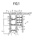
- einen Horizontalschnitt durch das Gestellteil und den befestigten Kabeln und
- Fig. 2
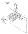
- eine perspektivische Darstellung der Winkelstücke der Befestigungsvorrichtung.
- Wie die Fig. 1 zeigt, bestehen die Mittel der Befestigungseinrichtung 8 aus Zahnstangen 1,2 und aus mindestens einem Federelement 3. Die Zahnstangen 1,2 sind an den längeren Schenkelseiten 9 eines Winkelstückes 10 angeordnet, wie auch Fig. 2 zeigt. Das kürzere Schenkelende 11 ist mit einer Bohrung 12 versehen, so daß das Winkelstück 10 an einem Gestellteil 13 mittels Schrauben oder mittels einer Nietverbindung befestigbar ist. Das Gestellteil 13 ist mit einem Gestellrahmen 14 verbunden, wobei mehrere Gestellrahmen ein Verteilergestell bilden.
- Das Federelement 3,4 besteht aus einer metallischen Klammer 19 mit einem Mittelteil 20 und mit zwei Enden 5,18. Die Enden 5 des Federelementes 3 sind bogenförmig und die Enden 18 des Federelementes 4 geradlinig ausgebildet. Wie in der Fig. 1 dargestellt ist, besitzt das längere Schenkelende 9 des Winkelstückes 10 beidseitig angeordnete Zahnstangen 1,2.
- Zur Befestigung der Kabel 6,7 an das Gestellteil 13 werden die Winkelstücke 10 am Gestellteil 13 befestigt, wobei das kürzere Schenkelende 11 am Gestellteil 13 angeschraubt wird. Das längere Schenkelende 9 des Winkelstückes 10 ist freistehend nach vorne gerichtet. Unmittelbar an die Stirnseite 16 des kürzeren Schenkelendes 11 werden die weiteren Winkelstück 10 befestigt, so daß mehrere Schenkelenden 9 parallel nebeneinander angeordnet sind. Zwischen den Schenkelenden 9 werden Aufnahmeräume 17 gebildet, die durch die beidseitig angeordneten Zahnstangen 1,2 begrenzt sind. Die Zähne 15 zweier Zahnstangen 1,2 zweier Winkelstücke 10 sind somit zueinander gerichtet. In die Aufnahmeräume 17 werden die Kabel 6, eingelegt und mittels der Federelemente 3,4 befestigt. Die Federelemente 3,4 werden hierbei in Pfeilrichtung A zwischen zwei Zahnstangen 1,2 eingeschoben und in Pfeilrichtung B an das Kabel 6 angedrückt. Hierbei klemmen die äußeren Enden 5,18 der Federelemente 3,4 jeweils zwischen zwei Zähnen 15 der Zahnstangen 1 und 2 ein und klemmen das Kabel 6,7 fest. Wie die Figur 1 zeigt, können mehrere Kabel 6 innerhalb eines Aufnahmeraumes 17 hintereinander zwischen den Zahnstangen 1 und 2 befestigt werden. Des weiteren ist dargestellt, daß das Federelement 3 bogenförmige Enden 5 aufweist. Das Kabel 6 liegt einerseits zwischen den bogenförmigen Enden 5 am Mittelteil 20 und anderseits an einer Anlagefläche 21 an.
- Das Federelement 4 weist geradlinig abgebogene Enden 18 auf, die vom Mittelteil 20 abgebogen sind. Zur besseren Klemmung kann das Federelement 4 auch vier Enden 18 aufweisen, die zwischen den Zähnen 15 der Zahnstange 1,2 einrasten. Am oberen Ende ist das Federelement 4 mit einem Anschlag 22 versehen, deren untere Seitenflächen 23 auf den Schmalseiten 24 der längeren Schenkelenden 9 der Winkelstücke 10 aufliegen und ein weiteres Eindrücken des Federelementes 3,4 in Pleirichtung A verhindern. Der Anschlag dient auch zur Führung beim Einschieben und beim Abziehen des Federelementes. Wie weiterhin dargestellt ist, können auch zwei Kabel 7, die nebeneinander liegen mittels eines Federelementes 3,4 zwischen den Zahnstangen 1,2 befestigt werden. In vorteilhafter Weise lassen sich somit eine Vielzahl von Kabeln mit unterschiedlichsten Kabeldurchmessern am Gestellteil 13 befestigen.
-
- 1,2
- Zahnstange
- 3,4
- Ferderelement
- 5
- Enden
- 6,7
- Kabel
- 8
- Befestigungsvorrichtung
- 9
- längeres Schenkelende
- 10
- Winkelstück
- 11
- kürzeres Schenkelende
- 12
- Bohrung 13
- 13
- Gestellteil
- 14
- Gestellrahmen
- 15
- Zähne
- 16
- Stirnseite
- 17
- Aufnahmeräume
- 18
- Enden
- 19
- Klammer
- 20
- Mittelteil
- 21
- Anlagefläche
- 22
- Anschlag
- 23
- Seitenfächen
- 24
- Schmalseiten
Claims (7)
- Vorrichtung zur Befestigung von Kabeln, insbesondere Fernmelde- und Datenkabeln an Gestellen oder Gehäusen von fernmeldetechnischen Einrichtungen,
dadurch gekennzeichnet,
daß Mittel vorgesehen sind, die die Kabel (6,7) klemmend an den Gestell- oder Gehäuseteilen (13) befestigen. - Vorrichtung nach Anspruch 1,
dadurch gekennzeichnet,
daß die Mittel aus zwei parallel zueinander angeordneten Zahnstangen (1,2) bestehen, zwischen denen ein Federelement (3,4) klemmbar ist. - Vorrichtung nach den Ansprüchen 1 und 2,
dadurch gekennzeichnet,
daß das Federelement (3,4) aus einer Klammer (19) mit einem Mittelteil (20) und mit zwei Enden (5,18) gebildet ist, die jeweils zwischen zwei Zähnen (15) der Zahnstange (1,2) eingreifen. - Vorrichtung nach den vorhergehenden Ansprüchen,
dadurch gekennzeichnet,
daß die Enden (5) des Federelementes (3) bogenförmig ausgebildet sind. - Vorrichtung nach den vorhergehenden Ansprüchen,
dadurch gekennzeichnet,
daß das Kabel zwischen den Enden (5,18) und dem Mittelteil (20) einerseits und einer Anlagefläche (21) andererseits klemmend befestigt ist. - Vorrichtung nach den vorhergehenden Ansprüchen,
dadurch gekennzeichnet,
daß mehrere Kabel (6,7) hintereinander durch mehrere Federelemente (3,4) zwischen den Zahnstangen (1,2) innerhalb eiens Aufnahmeraumes (17) befestigt sind. - Vorrichtung nach den vorhergehenden Ansprüchen,
dadurch gekennzeichnet,
daß mehrere Kabel (7) mittels eines Federelementes (3,4) befestigbar sind.
Applications Claiming Priority (2)
| Application Number | Priority Date | Filing Date | Title |
|---|---|---|---|
| DE4009297A DE4009297A1 (de) | 1990-03-20 | 1990-03-20 | Vorrichtung zur befestigung von kabeln |
| DE4009297 | 1990-03-20 |
Publications (3)
| Publication Number | Publication Date |
|---|---|
| EP0447834A2 true EP0447834A2 (de) | 1991-09-25 |
| EP0447834A3 EP0447834A3 (en) | 1992-01-08 |
| EP0447834B1 EP0447834B1 (de) | 1994-04-06 |
Family
ID=6402858
Family Applications (1)
| Application Number | Title | Priority Date | Filing Date |
|---|---|---|---|
| EP91102642A Expired - Lifetime EP0447834B1 (de) | 1990-03-20 | 1991-02-22 | Vorrichtung zur Befestigung von Kabeln |
Country Status (5)
| Country | Link |
|---|---|
| EP (1) | EP0447834B1 (de) |
| AT (1) | ATE104034T1 (de) |
| DE (2) | DE4009297A1 (de) |
| DK (1) | DK0447834T3 (de) |
| ES (1) | ES2055473T3 (de) |
Cited By (1)
| Publication number | Priority date | Publication date | Assignee | Title |
|---|---|---|---|---|
| CN110671541A (zh) * | 2019-09-18 | 2020-01-10 | 马鞍山汉德绿色建筑环境科技有限公司 | 一种拼接式管道支架 |
Families Citing this family (3)
| Publication number | Priority date | Publication date | Assignee | Title |
|---|---|---|---|---|
| DE19926332C1 (de) * | 1999-06-09 | 2001-02-01 | Krone Gmbh | Kabelklemme |
| DE10146119C1 (de) * | 2001-09-19 | 2002-12-19 | Krone Gmbh | Zugentlastung für einen Steckverbinder in der Kommunikations- und Datentechnik |
| DE102013200276A1 (de) * | 2013-01-10 | 2014-07-24 | Oliver Renaux | Vorrichtung zur Führung von Leitungen |
Family Cites Families (4)
| Publication number | Priority date | Publication date | Assignee | Title |
|---|---|---|---|---|
| DE2226677C3 (de) * | 1972-05-31 | 1978-04-20 | Siemens Ag, 1000 Berlin Und 8000 Muenchen | Kabelhalterung |
| IT1006335B (it) * | 1974-02-11 | 1976-09-30 | Itw Fastex Italia Spa | Dispositivo di fissaggio dei ca vi multipolari tipo piattina per correnti deboli a pareti di ap parecchiature elettroniche |
| NL7507979A (en) * | 1975-07-04 | 1977-01-06 | Researchcentrum Ogemat | Cable television distribution network - individual subscriber's coaxial cables avoid crosstalk and simplify installation |
| US4395009A (en) * | 1981-05-28 | 1983-07-26 | The Boeing Company | Raceway clamp |
-
1990
- 1990-03-20 DE DE4009297A patent/DE4009297A1/de active Granted
-
1991
- 1991-02-22 ES ES91102642T patent/ES2055473T3/es not_active Expired - Lifetime
- 1991-02-22 DE DE91102642T patent/DE59101304D1/de not_active Expired - Fee Related
- 1991-02-22 EP EP91102642A patent/EP0447834B1/de not_active Expired - Lifetime
- 1991-02-22 DK DK91102642.5T patent/DK0447834T3/da active
- 1991-02-22 AT AT91102642T patent/ATE104034T1/de not_active IP Right Cessation
Cited By (1)
| Publication number | Priority date | Publication date | Assignee | Title |
|---|---|---|---|---|
| CN110671541A (zh) * | 2019-09-18 | 2020-01-10 | 马鞍山汉德绿色建筑环境科技有限公司 | 一种拼接式管道支架 |
Also Published As
| Publication number | Publication date |
|---|---|
| DE59101304D1 (de) | 1994-05-11 |
| DE4009297C2 (de) | 1992-02-13 |
| DK0447834T3 (da) | 1994-05-02 |
| ES2055473T3 (es) | 1994-08-16 |
| DE4009297A1 (de) | 1991-09-26 |
| ATE104034T1 (de) | 1994-04-15 |
| EP0447834A3 (en) | 1992-01-08 |
| EP0447834B1 (de) | 1994-04-06 |
Similar Documents
| Publication | Publication Date | Title |
|---|---|---|
| DE19654611B4 (de) | Federkraftklemmanschluß für elektrische Leiter | |
| DE3411914C1 (de) | Vorrichtung zum Verbinden von Wandelementen,fuer Druckerboecke in Druckeinrichtungen | |
| DE29602589U1 (de) | Kastenschleifleitung | |
| DE2020383C3 (de) | Kennzeichnungsvorrichtung für eine elektrische Leitung | |
| DE19604564C1 (de) | Anschlußdose für ein Datennetz | |
| EP0778711B1 (de) | Steckverteiler, insbesondere für Datenübertragungsnetze | |
| EP0447834B1 (de) | Vorrichtung zur Befestigung von Kabeln | |
| EP1462808B1 (de) | Anschlussvorrichtung für einen Stromzähler | |
| DE3308568A1 (de) | Kabelklemme | |
| DE202008017555U1 (de) | Vorrichtung zur Führung und Halterung von Kabeln oder Schläuchen | |
| DE2638604C2 (de) | Mehrpolige Stiftleiste für Drahtwickelverbindungen | |
| DE2428882C2 (de) | Verfahren zum Befestigen eines Kabelbaums an einer gedruckten Leiterplatte | |
| DE7902093U1 (de) | Kontakteinsatz, bestehend aus einer Klemmfeder und einem Kontaktrahmen, insbesondere für Lichtbänder | |
| DE3016625C2 (de) | Sammelschiene | |
| DE3335194C2 (de) | ||
| DE4419785A1 (de) | Zugentlastungsvorrichtung | |
| CH662676A5 (de) | Kabel-kamm fuer elektrische installationen. | |
| DE2015338C3 (de) | Parallelverteiler | |
| AT406990B (de) | Anordnung zur zugentlastung | |
| DE1591435C3 (de) | Andrückkontakteinrichtung für Fern-Meldeanlagen, insbesondere für einschiebbare Baugruppen in Fernsprechanlagen | |
| DE9211879U1 (de) | Elektrischer Baustein | |
| DE202022105103U1 (de) | Elektronikmodul mit integrierter Leiterplattenaufnahme zur Kontaktierung zumindest eines Drahtes mit einer in der Leiterplattenaufnahme anordenbaren Leiterplatte | |
| DE8812389U1 (de) | Anschellvorrichtung für Geräteanschlußkabel | |
| DE9204909U1 (de) | Kabelhalter | |
| DE202005017682U1 (de) | Steckverbinder |
Legal Events
| Date | Code | Title | Description |
|---|---|---|---|
| PUAI | Public reference made under article 153(3) epc to a published international application that has entered the european phase |
Free format text: ORIGINAL CODE: 0009012 |
|
| AK | Designated contracting states |
Kind code of ref document: A2 Designated state(s): AT BE CH DE DK ES FR GB GR IT LI LU NL SE |
|
| PUAL | Search report despatched |
Free format text: ORIGINAL CODE: 0009013 |
|
| AK | Designated contracting states |
Kind code of ref document: A3 Designated state(s): AT BE CH DE DK ES FR GB GR IT LI LU NL SE |
|
| 17P | Request for examination filed |
Effective date: 19911128 |
|
| 17Q | First examination report despatched |
Effective date: 19920922 |
|
| GRAA | (expected) grant |
Free format text: ORIGINAL CODE: 0009210 |
|
| AK | Designated contracting states |
Kind code of ref document: B1 Designated state(s): AT BE CH DE DK ES FR GB GR IT LI LU NL SE |
|
| REF | Corresponds to: |
Ref document number: 104034 Country of ref document: AT Date of ref document: 19940415 Kind code of ref document: T |
|
| ITF | It: translation for a ep patent filed | ||
| REG | Reference to a national code |
Ref country code: DK Ref legal event code: T3 |
|
| REF | Corresponds to: |
Ref document number: 59101304 Country of ref document: DE Date of ref document: 19940511 |
|
| GBT | Gb: translation of ep patent filed (gb section 77(6)(a)/1977) |
Effective date: 19940418 |
|
| ET | Fr: translation filed | ||
| REG | Reference to a national code |
Ref country code: GR Ref legal event code: FG4A Free format text: 3011362 |
|
| REG | Reference to a national code |
Ref country code: ES Ref legal event code: FG2A Ref document number: 2055473 Country of ref document: ES Kind code of ref document: T3 |
|
| EAL | Se: european patent in force in sweden |
Ref document number: 91102642.5 |
|
| PGFP | Annual fee paid to national office [announced via postgrant information from national office to epo] |
Ref country code: LU Payment date: 19950201 Year of fee payment: 5 |
|
| PGFP | Annual fee paid to national office [announced via postgrant information from national office to epo] |
Ref country code: GB Payment date: 19950202 Year of fee payment: 5 |
|
| PLBE | No opposition filed within time limit |
Free format text: ORIGINAL CODE: 0009261 |
|
| STAA | Information on the status of an ep patent application or granted ep patent |
Free format text: STATUS: NO OPPOSITION FILED WITHIN TIME LIMIT |
|
| PGFP | Annual fee paid to national office [announced via postgrant information from national office to epo] |
Ref country code: FR Payment date: 19950214 Year of fee payment: 5 Ref country code: DE Payment date: 19950214 Year of fee payment: 6 |
|
| PGFP | Annual fee paid to national office [announced via postgrant information from national office to epo] |
Ref country code: DK Payment date: 19950221 Year of fee payment: 5 Ref country code: AT Payment date: 19950221 Year of fee payment: 5 |
|
| PGFP | Annual fee paid to national office [announced via postgrant information from national office to epo] |
Ref country code: SE Payment date: 19950223 Year of fee payment: 5 |
|
| PGFP | Annual fee paid to national office [announced via postgrant information from national office to epo] |
Ref country code: BE Payment date: 19950227 Year of fee payment: 5 |
|
| PGFP | Annual fee paid to national office [announced via postgrant information from national office to epo] |
Ref country code: NL Payment date: 19950228 Year of fee payment: 5 Ref country code: GR Payment date: 19950228 Year of fee payment: 5 Ref country code: ES Payment date: 19950228 Year of fee payment: 5 |
|
| PGFP | Annual fee paid to national office [announced via postgrant information from national office to epo] |
Ref country code: CH Payment date: 19950317 Year of fee payment: 5 |
|
| 26N | No opposition filed | ||
| PG25 | Lapsed in a contracting state [announced via postgrant information from national office to epo] |
Ref country code: LU Free format text: LAPSE BECAUSE OF NON-PAYMENT OF DUE FEES Effective date: 19960222 Ref country code: GB Effective date: 19960222 Ref country code: DK Effective date: 19960222 Ref country code: AT Effective date: 19960222 |
|
| REG | Reference to a national code |
Ref country code: DK Ref legal event code: EBP |
|
| PG25 | Lapsed in a contracting state [announced via postgrant information from national office to epo] |
Ref country code: SE Effective date: 19960223 Ref country code: ES Free format text: LAPSE BECAUSE OF NON-PAYMENT OF DUE FEES Effective date: 19960223 |
|
| PG25 | Lapsed in a contracting state [announced via postgrant information from national office to epo] |
Ref country code: LI Free format text: LAPSE BECAUSE OF NON-PAYMENT OF DUE FEES Effective date: 19960228 Ref country code: CH Free format text: LAPSE BECAUSE OF NON-PAYMENT OF DUE FEES Effective date: 19960228 Ref country code: BE Effective date: 19960228 |
|
| BERE | Be: lapsed |
Owner name: KRONE A.G. Effective date: 19960228 |
|
| PG25 | Lapsed in a contracting state [announced via postgrant information from national office to epo] |
Ref country code: GR Free format text: THE PATENT HAS BEEN ANNULLED BY A DECISION OF A NATIONAL AUTHORITY Effective date: 19960831 |
|
| PG25 | Lapsed in a contracting state [announced via postgrant information from national office to epo] |
Ref country code: NL Effective date: 19960901 |
|
| GBPC | Gb: european patent ceased through non-payment of renewal fee |
Effective date: 19960222 |
|
| REG | Reference to a national code |
Ref country code: CH Ref legal event code: PL |
|
| PG25 | Lapsed in a contracting state [announced via postgrant information from national office to epo] |
Ref country code: FR Effective date: 19961031 |
|
| REG | Reference to a national code |
Ref country code: GR Ref legal event code: MM2A Free format text: 3011362 |
|
| NLV4 | Nl: lapsed or anulled due to non-payment of the annual fee |
Effective date: 19960901 |
|
| REG | Reference to a national code |
Ref country code: FR Ref legal event code: ST |
|
| PG25 | Lapsed in a contracting state [announced via postgrant information from national office to epo] |
Ref country code: DE Effective date: 19971101 |
|
| REG | Reference to a national code |
Ref country code: ES Ref legal event code: FD2A Effective date: 19990301 |
|
| PG25 | Lapsed in a contracting state [announced via postgrant information from national office to epo] |
Ref country code: IT Free format text: LAPSE BECAUSE OF NON-PAYMENT OF DUE FEES;WARNING: LAPSES OF ITALIAN PATENTS WITH EFFECTIVE DATE BEFORE 2007 MAY HAVE OCCURRED AT ANY TIME BEFORE 2007. THE CORRECT EFFECTIVE DATE MAY BE DIFFERENT FROM THE ONE RECORDED. Effective date: 20050222 |