EP0447709A2 - Magnetisch angetriebene Pumpe - Google Patents
Magnetisch angetriebene Pumpe Download PDFInfo
- Publication number
- EP0447709A2 EP0447709A2 EP90310639A EP90310639A EP0447709A2 EP 0447709 A2 EP0447709 A2 EP 0447709A2 EP 90310639 A EP90310639 A EP 90310639A EP 90310639 A EP90310639 A EP 90310639A EP 0447709 A2 EP0447709 A2 EP 0447709A2
- Authority
- EP
- European Patent Office
- Prior art keywords
- casing
- impeller
- magnet
- shaft
- heat
- Prior art date
- Legal status (The legal status is an assumption and is not a legal conclusion. Google has not performed a legal analysis and makes no representation as to the accuracy of the status listed.)
- Granted
Links
- 238000005096 rolling process Methods 0.000 claims description 60
- 239000007788 liquid Substances 0.000 claims description 27
- 239000000463 material Substances 0.000 claims description 15
- 238000007599 discharging Methods 0.000 claims description 5
- 230000003139 buffering effect Effects 0.000 claims description 4
- 230000002159 abnormal effect Effects 0.000 abstract description 2
- 239000000126 substance Substances 0.000 description 25
- 238000010276 construction Methods 0.000 description 7
- 230000000694 effects Effects 0.000 description 6
- 229920003002 synthetic resin Polymers 0.000 description 6
- 239000000057 synthetic resin Substances 0.000 description 6
- -1 for example Polymers 0.000 description 4
- 238000005299 abrasion Methods 0.000 description 3
- 239000000919 ceramic Substances 0.000 description 3
- 238000009792 diffusion process Methods 0.000 description 3
- 239000012530 fluid Substances 0.000 description 3
- 239000003779 heat-resistant material Substances 0.000 description 3
- 230000007257 malfunction Effects 0.000 description 3
- 239000011148 porous material Substances 0.000 description 3
- 229920005989 resin Polymers 0.000 description 3
- 239000011347 resin Substances 0.000 description 3
- 238000007789 sealing Methods 0.000 description 3
- 239000004743 Polypropylene Substances 0.000 description 2
- 238000013019 agitation Methods 0.000 description 2
- 230000002093 peripheral effect Effects 0.000 description 2
- 229920001155 polypropylene Polymers 0.000 description 2
- 230000035939 shock Effects 0.000 description 2
- 230000007704 transition Effects 0.000 description 2
- 239000002253 acid Substances 0.000 description 1
- 230000032683 aging Effects 0.000 description 1
- PNEYBMLMFCGWSK-UHFFFAOYSA-N aluminium oxide Inorganic materials [O-2].[O-2].[O-2].[Al+3].[Al+3] PNEYBMLMFCGWSK-UHFFFAOYSA-N 0.000 description 1
- 239000002826 coolant Substances 0.000 description 1
- 231100001261 hazardous Toxicity 0.000 description 1
- 238000009413 insulation Methods 0.000 description 1
- 238000000034 method Methods 0.000 description 1
- 239000004033 plastic Substances 0.000 description 1
- 230000002265 prevention Effects 0.000 description 1
- 230000037452 priming Effects 0.000 description 1
Images


Classifications
-
- F—MECHANICAL ENGINEERING; LIGHTING; HEATING; WEAPONS; BLASTING
- F04—POSITIVE - DISPLACEMENT MACHINES FOR LIQUIDS; PUMPS FOR LIQUIDS OR ELASTIC FLUIDS
- F04D—NON-POSITIVE-DISPLACEMENT PUMPS
- F04D29/00—Details, component parts, or accessories
- F04D29/58—Cooling; Heating; Diminishing heat transfer
-
- F—MECHANICAL ENGINEERING; LIGHTING; HEATING; WEAPONS; BLASTING
- F04—POSITIVE - DISPLACEMENT MACHINES FOR LIQUIDS; PUMPS FOR LIQUIDS OR ELASTIC FLUIDS
- F04D—NON-POSITIVE-DISPLACEMENT PUMPS
- F04D29/00—Details, component parts, or accessories
- F04D29/04—Shafts or bearings, or assemblies thereof
- F04D29/046—Bearings
- F04D29/049—Roller bearings
-
- F—MECHANICAL ENGINEERING; LIGHTING; HEATING; WEAPONS; BLASTING
- F04—POSITIVE - DISPLACEMENT MACHINES FOR LIQUIDS; PUMPS FOR LIQUIDS OR ELASTIC FLUIDS
- F04D—NON-POSITIVE-DISPLACEMENT PUMPS
- F04D13/00—Pumping installations or systems
- F04D13/02—Units comprising pumps and their driving means
- F04D13/021—Units comprising pumps and their driving means containing a coupling
- F04D13/024—Units comprising pumps and their driving means containing a coupling a magnetic coupling
- F04D13/025—Details of the can separating the pump and drive area
-
- F—MECHANICAL ENGINEERING; LIGHTING; HEATING; WEAPONS; BLASTING
- F04—POSITIVE - DISPLACEMENT MACHINES FOR LIQUIDS; PUMPS FOR LIQUIDS OR ELASTIC FLUIDS
- F04D—NON-POSITIVE-DISPLACEMENT PUMPS
- F04D13/00—Pumping installations or systems
- F04D13/02—Units comprising pumps and their driving means
- F04D13/021—Units comprising pumps and their driving means containing a coupling
- F04D13/024—Units comprising pumps and their driving means containing a coupling a magnetic coupling
- F04D13/026—Details of the bearings
-
- F—MECHANICAL ENGINEERING; LIGHTING; HEATING; WEAPONS; BLASTING
- F04—POSITIVE - DISPLACEMENT MACHINES FOR LIQUIDS; PUMPS FOR LIQUIDS OR ELASTIC FLUIDS
- F04D—NON-POSITIVE-DISPLACEMENT PUMPS
- F04D29/00—Details, component parts, or accessories
- F04D29/04—Shafts or bearings, or assemblies thereof
- F04D29/041—Axial thrust balancing
- F04D29/0413—Axial thrust balancing hydrostatic; hydrodynamic thrust bearings
-
- F—MECHANICAL ENGINEERING; LIGHTING; HEATING; WEAPONS; BLASTING
- F04—POSITIVE - DISPLACEMENT MACHINES FOR LIQUIDS; PUMPS FOR LIQUIDS OR ELASTIC FLUIDS
- F04D—NON-POSITIVE-DISPLACEMENT PUMPS
- F04D29/00—Details, component parts, or accessories
- F04D29/58—Cooling; Heating; Diminishing heat transfer
- F04D29/586—Cooling; Heating; Diminishing heat transfer specially adapted for liquid pumps
- F04D29/5893—Cooling; Heating; Diminishing heat transfer specially adapted for liquid pumps heat insulation or conduction
Definitions
- This invention relates to a magnetic pump.
- a relatively low cost pump which comprises elements made of synthetic resin resistant to such chemical liquid.
- a chemical liquid When a chemical liquid is treated, it is required that a shaft and a casing of the pump are completely sealed. This is because on many occasions such chemical liquid may be expensive and also hazardous to the human body.
- a magnetic pump which does not have a shaft sealing member for sealing between the shaft and casing so as to avoid leakage of chemical liquid.
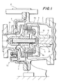
- FIG 1 shows a conventional magnetic pump 1a as mentioned above.
- the magnet pump 1a comprises a casing 3 in which a fixed shaft 6 is accommodated.
- An impeller 8 is rotatably fitted on the shaft 6.
- a magnet can 10 is attached to the impeller 8 for accommodating a follower magnet 9a which is adapted to rotate the impeller 8 by transmitting rotations of a motor 28 (not shown in Figure 1).
- a driving magnet 9b is arranged in a rotating body 11 fitted on a rotating shaft 29 of the motor 28 at a position proximal to the casing 3.
- the shaft 6, serving as the rotating central axis for maintaining the rotation of the impeller 8, may rub with the impeller 8 to generate frictional heat.
- Such frictional heat is cooled down by chemical liquid flow during a normal operation.
- chemical liquid is not supplied from the inlet port 20 and the impeller 8 rotates without fluid flow, that is, during a non-load operation, the frictional heat is not cooled down and may cause problems, for example, deformation of synthetic resin members.
- prevention of the build up of frictional heat, that is, the non-load operation of the magnet pump 1a has been achieved by detecting a load current and stopping the magnetic pump 1a by an electrical or pressure control method.
- the conventional magnetic pump 1a normally employs the impeller 8 and the magnet can 10 made of non-heat resistant material such as synthetic resin. These elements are therefore inherently susceptible to deformation by receiving heat. Also, the wall of the casing 3 is very thin and spacing between the casing and the magnet can 10 is quite narrow so as to obtain a large rotating force of the magnet can 10. Consequently, deformation of these elements may cause collision of the magnet can 10 and/or the impeller 8 with the casing 3, cracks in the casing which prevent the impeller from rotating, and so on, whereby the function of the pump may be lost ultimately.
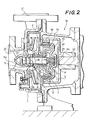
- the applicant has already provided a magnetic pump which can eliminate the above-mentioned inconveniences (see Published Japanese Patent Application (Kokai) No. 63-264812), as illustrated in Figure 2.
- a magnetic pump 1b shown frictional heat is generated in portions A and B by the rotation of the impeller 8.
- the magnet pump 1b is provided with a rolling bearing 27 having heat insulating grooves 25, 27, ..., a rear fixing bearing 4 having a heat insulating groove 4a, a front fixing bearing 5 having heat insulating grooves 5a, 5b, and a shaft 6 having heat insulating grooves 23, 24.
- the heat generated in the portions A, B is therefore diffused by the heat insulating grooves formed on these bearings 4, 5, 6 and 27 and insulated from the casing 3, the impeller 8, the magnet can 10 and so on, making it possible to prevent deformation, collisions and cracks from occurring in these elements.
- the magnetic pump 1b of the applicant even with the magnetic pump 1b of the applicant, if it is left in unfavorable operating conditions such as non-load operation, cavitation operation, shutout operation, insufficient load operation (insufficient priming), air lock operation, over-feeding, unstable feeding conditions caused by prerotation effects and so on (these operations or conditions are hereinafter represented by "the non-load operation") for a long period and if such conditions are detected too late, the heat generated in the portions A, B is gradually accumulated therein and conducted to the magnet can 10, the impeller 8 and the casing 3. As a result, the temperature is increased to cause deformation of these elements.
- unfavorable operating conditions such as non-load operation, cavitation operation, shutout operation, insufficient load operation (insufficient priming), air lock operation, over-feeding, unstable feeding conditions caused by prerotation effects and so on (these operations or conditions are hereinafter represented by "the non-load operation"
- the present invention provides a magnetic pump which comprises: an impeller rotatably fitted on a shaft accommodated and fixed in a casing; and a rolling bearing and a heat insulating member disposed between the shaft and the impeller and provided with heat conduction cut-off grooves.
- a magnetic pump 1 includes a housing 2 and a casing 3 which is accommodated in the housing 2.
- a shaft 6 is accommodated in the casing 3 and fixed by rear and front fixing bearings 4, 5.
- An impeller 8 is rotatably provided on the shaft 6 through a rolling bearing 7 and a heat insulating member 40 fitted on the outer periphery of the rolling bearing 7.
- a safety lock 30 is provided between the impeller 8 and the casing 3 for safely locking the pump when a malfunction occurs.
- a driving section 12 includes a magnet can 10, fixed to the impeller 8, for accommodating a follower magnet 9a and a rotating body 11, arranged outside the casing 3, for accommodating a driving magnet 9b for rotating the impeller 8 together with the follower magnet 9a in the magnet can 10.
- the housing 2 comprises a motor bracket 13, a suction flange 14 and a discharge flange 15 and is arranged to accommodate and hold the casing 3. These elements can respectively be secured by bolts or the like. Since the housing 2 does not directly contact with chemical liquid, its mechanical strength is considered more important than its resistivity to chemicals, so that a molded housing is normally employed as the housing 2.
- the material for the casing 3 is selected with due regard to the resistivity to chemical liquid.
- the casing 3 is made of synthetic resin, for example, polypropylene, fluororesin, or the like.
- the casing 3 is formed of a rear casing 16 and a front casing 17 which are tightly coupled to each other through a seal member 19 so as to provide a complete fluid tight structure.
- the front casing 17 is provided with a suction port 20 and a discharge port 21.
- the rear and front casings 16, 17 are provided with fixing grooves 16a, 17a, respectively, to which rear and front fixing bearings 4, 5 are fixed, respectively.
- rear and front fixing bearings 4, 5 are provided with heat conduction cut-off grooves 4a, 5a formed thereon, respectively, which are adapted, as will be explained later in detail, to cut off conduction of frictional heat generated by friction between the shaft 6 and the rolling bearing 7 and friction between the rolling bearing 7 and a front thrust bearing 22, later referred to, and prevent such frictional heat from being conducted to the rear casing 16 and the front casing 17.
- the front fixing bearing 5 is provided with a liquid introducing path 5b and a heat discharging hole 5c, so that the distance from the shaft 6 to the front casing is relatively long and accordingly the surface area thereof is large enough to promote frictional heat to diffuse therefrom.
- the rear and front fixing bearings 4, 5 may be made of a porous material such as ceramics.
- the porous material which contains a large quantity of air, serves to cut off heat conduction and accordingly prevent the above-mentioned frictional heat from being conducted.
- the rear fixing bearing 4 and the front fixing bearing 5 are made of a resin having a higher heat resistivity than the rear and front casings 16, 17, i.e., a resin, the heat distortion temperature of which is 180°C or more.
- the bearings 4, 5 are attached to the shaft 6 by shrink fitting so as to provide a loosening preventing mechanism. Therefore, even if the rear and front fixing bearings 4, 5 are heated to a high temperature by frictional heat, they will not be deformed so easily because of their heat-resistant material. Also, since they are shrink fitted, they will not become loose on the shaft 6 even with thermal expansion. Thus, it is ensured that the bearings 4, 5 will not shake with the shaft 6.
- the shaft 6 has its opposite end portions supported by the rear and front fixing bearing 4, 5 and provides the center of rotation for the impeller 8 and the magnet can 10 in which the follower magnet 9a is accommodated.
- the shaft 6 is made of a hard chemical-resistant material, for example, alumina ceramics.
- the outer peripheral surface of the shaft 6 is provided with a plurality of circular heat conduction cut-off grooves in the radial plane.
- the rear side outer peripheral surface of the shaft 6 is provided with a spline type heat conduction cut-off groove in the axial direction.
- These heat conduction cut-off grooves perform in a similar manner to the foregoing heat conduction cut-off grooves 4a, 5a. Specifically, they prevent the aforementioned frictional heat from being conducted to the rear and front casings 16, 17 through the rear and front fixing bearings 4, 5.
- the impeller 8 and the magnet can 10 are rotatably fitted on the shaft 6 through the rolling bearing 7 and the heat insulating member 40. Further, a front thrust bearing 22 and a rear thrust bearing 41 are respectively fixed thereon at axially opposite ends of the rolling bearing for supporting the thrust load of the impeller 8 and the magnet can 10.
- the rear and front thrust bearings 22, 41 are made of ceramics, and the load of the rear and front thrust bearings 22, 41 in the thrust direction is received by the front and rear fixing bearing 4, 5 through buffer members 42, 43 which are made of a shock softening material such as rubber and provided with heat conduction cut-off grooves 42a, 43a, respectively.
- the rolling bearing 7 is cylindrical and provided with a collar. It is rotatably and slidably fitted on the shaft 6 and adapted to rotate together with the impeller 8 and the magnet can 10.
- a cylindrical portion of the rolling bearing 7 is provided with substantially concentric heat conduction cut-off grooves 25 in the axial direction.
- the heat insulating member 40 fitted on the outer periphery of the rolling bearing 7 is made of porous material and provided with substantially concentric heat conduction cut-off grooves 40a in a similar manner to the rolling bearing 7.
- rolling bearing 7 and heat insulating member 40 have a double structure in a similar manner to a thermal bottle.
- the double structure of the rolling bearing 7 and heat insulating member 40 is formed by the heat conduction cut-off grooves 25, 40a, respectively, such that the conduction of frictional heat generated by the aforementioned friction is prevented by means of an air layer having a low heat conductivity in the heat conduction cut-off grooves 25, 40a and the heat insulating property of the heat insulating member 40, whereby the frictional heat is not conducted to the casing 3, the impeller 8 and the magnet can 10. Further, rotations of these heat conduction cut-off grooves 25, 41a cause the air existing therein to be agitated, so that frictional heat reaching the surface of the heat conduction cut-off grooves 25, 41a is diffused.
- the heat insulating member 40 is not integrated with the rolling bearing 7, it is possible to arbitrarily choose material having a high heat insulating property irrespective of the material required for the rolling bearing 7.
- the heat insulating member 40 is made of a material having a higher heat resistivity than that of the magnet can 10, for example, a resin, the heat distortion temperature of which is 180° or more, and is shrink fitted about the shaft 6 to provide a looseness preventing mechanism. Therefore, even if a high temperature is generated by frictional heat in the heat insulating member 40, it will not suffer from distortion because of the high heat resistance of the material employed, and also by virtue of shrink fitting it will not become loose about the shaft 6 even with thermal expansion. Thus, it is ensured that the bearings 4, 5 will not shake relative to the rolling bearing 7.
- the impeller 8 is of non-clogging type and made of material which is selected sufficiently taking consideration of resistivity to chemicals and strength.
- a synthetic resin for example, polypropylene, fluororesin, or the like is employed.
- the safety lock 30 comprises a main lock 31 and an auxiliary lock 32, as shown in Figure 4.
- the main lock 31 has a main bush 33 removably fitted in a ring-shaped groove 17b formed on the front casing 17, and a protrusion 34 attached to the impeller 8 so as to be rotatable in a ring groove 35 of the main bush 33.
- the ring groove 35 of the main bush 33 and the protrusion 34 are arranged to be engaged with each other as a main means of locking the pump.
- the auxiliary lock 32 has an auxiliary bush 36 removably fitted in a L-shaped groove 17c formed on the front casing 17, wherein the auxiliary bush 36 and a protrusion 8a at the tip of the impeller 8 are also engaged with each other to additionally lock the pump.
- Main lock 31 and auxiliary lock 32 are provided to lock the pump before the casing 3 comes into contact with the magnet can 10 and the impeller 8 when a deflection a in rotation of the impeller 8 and the magnet can 10 exceeds a predetermined amount ( ⁇ or ⁇ , which will be explained later).
- a deflection in rotation is typically caused by abnormal friction caused by sliding of the shaft 6 and the rolling bearing 7, thermal distortion of the rear and front fixing bearings 4, 5, and thermal distortion of the heat insulating member 40 carrying the rolling bearing 7.
- the main lock 31 is operative to lock the pump.
- the main bush 33 of the main lock 31 and the auxiliary bush 36 of the auxiliary lock 32 are made of wear-resistant material and replaced when they are worn by a predetermined amount.
- the safety lock 30 is not limited to be located at the place selected by the present embodiment and may be located at any other suitable place.
- the driving section comprising the magnet can 10 and the rotating body 11 is adapted to rotate the impeller 8.
- the rotating body 11 is coupled to the shaft 29 of the motor 28 supported by a motor bracket 13. Therefore, rotation of the shaft 29 of the motor 28 causes the driving magnet 9b accommodated in the rotating body 11 to be also rotated. Rotation of the driving magnet 9b incurs rotation of the follower magnet 9a, whereby the magnet can 10 and also the impeller 8 are rotated.
- a gap between the two magnets 9a, 9b is formed as narrow as possible.
- the aforementioned gap ⁇ between the inner wall surface of the rear casing 16 and the outer surface of the magnet can 10 is approximately 2 - 3 m/m.
- the magnetic pump 1 as shown in Figure 3, has a spacing between the rotating shaft 7 and the front and rear thrust bearings 22, 41.
- the follower magnet 9a is attracted and fixed by the driving magnet 9b with the spacing maintained.
- the magnetic pump 1 has the casing 3 normally filled with chemical liquid or the like.
- the chemical liquid is fed from the suction port 20 into the casing 3 and discharged from the discharge port 21 after being given a predetermined pressure by the impeller 8.
- the opposite ends of the shaft 6 are fixed to the casing 3 through the rear and front fixing bearings 4, 5.
- the front and rear thrust bearings 22, 41 are supported by the front and rear fixing bearings 4, 5 through buffer members 42, 43, respectively.
- the impeller 8 and the magnet can 10 are rotated about the shaft 6 through the heat insulating member 40 and the rolling bearing 7, so that the impeller 8 obtains a thrust on the front side while the rolling bearing 7 is rotated about the shaft 6 and the front thrust bearing 22 in a sliding manner, whereby frictional heat is generated therebetween.
- frictional heat is cooled down by the chemical liquid filling the casing 3, thus avoiding damages caused by the frictional heat.
- the magnetic pump 1 is not provided with chemical liquid serving as coolant nor the above-mentioned thrust toward the front side so that the rolling bearing 7 does not come into contact with the front and rear thrust bearings 22, 41, whereby frictional heat is generated in a sliding portion A between the shaft 6 and the rolling bearing 7 to cause a high temperature therein.
- This high temperature frictional heat generated in the sliding portion A tends mainly to be conducted to the impeller 8 and the magnet can 10 through the rolling bearing 7 and the heat insulating member 40, but is substantially prevented from being conducted by the double structure for heat insulation mainly formed by the heat conduction cut-off groove 25 of the rolling bearing 7 and the heat conduction cut-off groove 40a of the heat insulating member 40.
- the high temperature frictional heat reaching the surface of the heat conduction cut-off grooves 25, 40a is converted from conduction to convection, and further surrounding air is agitated by rotation of these grooves, whereby the high temperature frictional heat on the surface of the heat conduction cut-off grooves 25, 40a is cooled down by the agitated air.
- the heat insulating member 40 is separated from the rolling bearing 7, as mentioned above, the member is made of a material having a high heat insulating property so that the frictional heat is more efficiently insulated.
- the high temperature frictional heat generated in the sliding portion A tends mainly to be conducted to the shaft 6, the front fixing bearing 5 and the front casing 17, respectively, but is substantially prevented from being conducted by the heat conduction cut-off groove of the shaft 6, the heat conduction cut-off groove 5a of the front fixing bearing 5, the liquid introducing path 5b, the heat discharging hole 5c and the heat conduction cut-off groove 43a of the buffer member 42.
- the size of the front fixing bearing 5 is large and also the surface area thereof is rendered considerably large because of the liquid introducing path 5b, the heat discharging hole 5c and the heat conduction cut-off groove 5a, the high temperature frictional heat reaching the surface of these elements is converted from conduction to convection. Further, surrounding air is agitated by rotation of the impeller 8, whereby the high temperature frictional heat on the surface of the above elements is cooled down by air.
- the high temperature frictional heat generated in the sliding portion A is prevented from being conducted to the impeller 8, the magnet can 10 and the front casing 17, whereby these elements will never suffer from thermal distortion which may be otherwise caused by such frictional heat.
- the high temperature frictional heat generated in the sliding portion A also tends to be conducted to the rear casing 16 of the casing 3 through the shaft 6 and the fixing bearing 4.
- the heat conduction cut-off groove formed on the shaft 6 and the heat conduction cut-off groove 4a formed on the rear fixing bearing 4 substantially insulate the conduction of the frictional heat. More specifically, by virtue of the double thermal bottle-like structure made up of the heat conduction cut-off grooves provided for the shaft 6 and the rear fixing bearing 4, the frictional heat is converted from a conduction form to a convection form, or the frictional heat cannot be conducted easily. Thus, the high temperature frictional heat is hardly conducted to the rear casing 16 which will never be distorted thereby.
- the rear and front fixing bearings 4, 5, respectively provided with the looseness preventing mechanism, and the heat insulating member 40 are also heated and thermally expanded.
- the rear and front fixing bearings 4, 5 and the heat insulating member 40 are shrink fitted on the shaft 6 and the rolling bearings 7 whose thermal expansion is relatively small, so that looseness and backlash will never occur among these elements. Therefore, the impeller 8 and the magnet can 10 are substantially protected from making contact with the casing 3, making it possible to avoid damage and cracks in these rotating elements.
- the rear and front fixing bearings 4, 5 and the heat insulating member 40 since they are made of heat resistant material, will never suffer from thermal distortion.
- a long time unfavorable operation such as non-load operation may cause thermal expansion in the rear and front fixing bearings 4, 5 and the heat insulating member 40 which become loose on the shaft 6 and the rolling bearing 7 which have lower coefficients of thermal expansion than the elements 4, 5 and 40.
- the looseness of these elements results in deflection in rotation of the impeller 8 and the magnet can 10. If the deflection ⁇ reaches the predetermined amount ⁇ , the main lock 31 of the safety lock 30 is operated. More specifically, the ring groove 35 of the main bush 25 arranged on the front casing 17 comes into contact with the protrusion 34 of the impeller 8 to lock the pump.
- the auxiliary lock 32 is operated. More specifically, the auxiliary bush 36 arranged on the front casing 17 comes in contact with the protrusion 8a at the tip of the impeller 8 to lock the magnet pump 1. It is therefore possible to detect malfunction of the magnet pump 1 before the impeller 8 and/or the magnet can 10 come into contact with the casing 3, any of these elements is cracked, and chemical liquid leaks through thus formed cracks.
- FIG. 5 shows a second embodiment of a magnetic pump 1c of the present invention, in which the parts corresponding to those in Figure 3 are designated the same reference numerals and the detailed explanation thereof will be omitted.
- the magnetic pump 1c does not have the front fixing bearing 5 as shown in Figure 3, and the shaft 6 is cantilevered by the rear fixing bearing 4.
- the front casing 17 is provided with a thrust bearing ring 50 provided with a heat conduction cut-off groove 50a.
- a mouth ring 51 provided with a heat conduction cut-off groove 51a, is attached to the impeller 8 so as to be slidable on the thrust bearing ring 50.
- Figure 6 shows a third embodiment of the present invention.
- a magnetic pump 1d illustrated in Figure 6 differs from the first embodiment in Figure 3 in the following construction.
- the shaft 6 is rotatably mounted to the casing 3 through a rear rolling bearing 54 and a front rolling bearing 56 attached to a split plate 55 and fixed to the magnet can 10 through the impeller 8 and the fixing bearing 53.
- the front casing 17 is provided with a thrust bearing ring 50, and a mouth ring 51 is mounted on the impeller 8 so as to be slidably contacted to the thrust bearing ring 50.
- the fixing bearing 53, rear rolling bearing 54, split plate 55, front rolling bearing 56, thrust bearing ring 50 and mouth ring 51 are provided with heat conduction cut-off grooves 53a, 54a, 55a, 56a, 50a and 51a, respectively.
- FIG. 7 shows a fourth embodiment of the present invention.
- a magnetic pump 1e differs from the magnetic pump 1d illustrated in Figure 6 in that the former is provided with a looseness preventing mechanism and a safety lock mechanism.
- this looseness preventing mechanism is formed of a heat insulating members 57, 58 arranged between the rear casing 16 and the rear rolling bearing 54 and between the split plate 57 and the front rolling bearing 56, respectively.
- the heat insulating members 57, 58 and the fixing bearing 53 are made of a material having a higher heat resistivity than those of the rear casing 16, the split plate 55 and the magnet can 10, the thermal distortion temperature of which is 180°C or more, and are shrink fitted about the shaft 6.
- the safety lock mechanism comprises a safety lock 60 arranged between the casing 3 and the magnet can 10 and/or between the casing and the impeller 8.
- the safety lock 60 is made up of a main lock 61 and an auxiliary lock 62.
- the main lock 61 has a main bush 63 removably fitted in the ring-shaped groove 17b formed on the front casing 17, and a protrusion 64 attached to the impeller 8 so as to be rotatable in a ring groove 65 of the main bush 33.
- the ring groove 65 of the main bush 63 and the protrusion 64 are arranged to be engaged with each other as a main means of locking the pump.
- the auxiliary lock 62 has an auxiliary bush 66 removably fitted in a L-shaped groove 55c formed on the split plate 55, wherein the auxiliary bush 66 and a protrusion 8b at the tip of the impeller 8 also are engaged with each other to additionally lock the pump.
- the rest of the construction and the actions of the fourth embodiment are substantially equivalent to the aforementioned embodiments illustrated in Figures 3, 4 and 6, so that corresponding parts are designated the same reference numerals and the detailed explanation thereof will be omitted.
- provision of the heat conduction cut-off grooves on the heat insulating member is effective in diffusing the frictional heat by the above-mentioned double structure and agitated air, and in addition, the heat insulating property of a heat insulating member itself further inhibits the heat from being conducted. It is therefore possible in at least preferred embodiments to prevent the magnetic pump from falling into inoperative conditions such as a rotation impossible condition due to a contact between, for example, the impeller and the casing, and a hole or crack in the casing.
- a front side fixing bearing is separately provided between the casing and the shaft and frictional heat generated between the rolling bearing and the shaft is diffused from heat discharging holes and a liquid introducing path. Also, since the distance to the casing is relatively long in such an arrangement, the frictional heat is diffused from other surfaces of the front side fixing bearing. Thus, the frictional heat is further prevented from being conducted to the casing and other elements made of synthetic resin.
- the heat conduction cut-off grooves, if formed on the front side fixing bearing provide the aforementioned double structure and air agitation which further promotes diffusion of the frictional heat, and accordingly the same effects can be produced in such an arrangement.
- the casing by providing the casing with a thrust bearing ring provided with a heat conduction cut-off groove and a mouth ring provided with a heat conduction cut-off groove which is arranged slidably relative to the thrust bearing ring, frictional heat is diffused by a double-structure formed by the heat conduction cut-off grooves on the thrust bearing ring and the mouth ring and effects of agitated air, thereby producing the same effects as the above.
- the fixing bearing and the heat insulating member are thermally expanded by frictional heat generated between the rolling bearing and the shaft.
- the fixing bearing and the heat insulating member are shrink fitted on the shaft and the rolling bearing, so that the former elements do not become loose on the latter elements, and therefore backlash will not occur.
- a magnetic pump which has a magnet can accommodated in a casing and rotatably attached to a fixed shaft for rotating an impeller
- thermal distortion, abrasion and so on caused by frictional heat may result in deflection in rotation of the magnet can and the impeller.
- a safety lock is operated to prohibit the rotation of the magnet can, whereby the magnet can and the impeller do not come into contact with the casing.
- a magnetic pump in accordance with the present invention is particularly well adapted for use with chemical liquids but could also be used for other liquids generally.
- a durable magnetic pump which comprises means for removing heat typically generated during a non-load operation of the pump and thereby preventing damage possibly caused by such heat from occurring in elements of the pump made of plastic, rubber or the like; and there is provided a magnetic pump which can eliminate deformation of its elements such as a casing and an impeller, caused by a non-load operation of the pump or the like, and inoperable conditions resulting from cracks formed in a casing, while maintaining a high resistivity to acid and alkaline chemicals.
Landscapes
- Engineering & Computer Science (AREA)
- Mechanical Engineering (AREA)
- General Engineering & Computer Science (AREA)
- Physics & Mathematics (AREA)
- Thermal Sciences (AREA)
- Fluid Mechanics (AREA)
- Structures Of Non-Positive Displacement Pumps (AREA)
Applications Claiming Priority (2)
| Application Number | Priority Date | Filing Date | Title |
|---|---|---|---|
| JP2033514A JPH03237291A (ja) | 1990-02-14 | 1990-02-14 | マグネットポンプ |
| JP33514/90 | 1990-02-14 |
Publications (3)
| Publication Number | Publication Date |
|---|---|
| EP0447709A2 true EP0447709A2 (de) | 1991-09-25 |
| EP0447709A3 EP0447709A3 (en) | 1991-12-04 |
| EP0447709B1 EP0447709B1 (de) | 1995-06-28 |
Family
ID=12388656
Family Applications (1)
| Application Number | Title | Priority Date | Filing Date |
|---|---|---|---|
| EP90310639A Expired - Lifetime EP0447709B1 (de) | 1990-02-14 | 1990-09-28 | Magnetisch angetriebene Pumpe |
Country Status (5)
| Country | Link |
|---|---|
| US (1) | US5154587A (de) |
| EP (1) | EP0447709B1 (de) |
| JP (1) | JPH03237291A (de) |
| KR (1) | KR940011716B1 (de) |
| DE (1) | DE69020536T2 (de) |
Cited By (6)
| Publication number | Priority date | Publication date | Assignee | Title |
|---|---|---|---|---|
| DE19503353C2 (de) * | 1994-02-03 | 2001-08-23 | World Chem Kk | Selbstansaugende Chemikalienpumpe |
| EP2587066A3 (de) * | 2011-10-26 | 2015-09-30 | Assoma Inc. | Dauermagnetmotorpumpe |
| EP3273064A1 (de) * | 2011-11-03 | 2018-01-24 | Assoma Inc. | Magnetantriebspumpe |
| CN111089074A (zh) * | 2019-12-27 | 2020-05-01 | 珠海格力电器股份有限公司 | 转轴锁定装置、压缩机、空调器 |
| EP3610155A4 (de) * | 2017-04-11 | 2020-12-16 | FSubsea AS | Anordnung zur magnetischen kopplung |
| CN113614379A (zh) * | 2019-04-02 | 2021-11-05 | Ksb股份有限公司 | 热阻挡机构 |
Families Citing this family (15)
| Publication number | Priority date | Publication date | Assignee | Title |
|---|---|---|---|---|
| JP2569419B2 (ja) * | 1993-02-18 | 1997-01-08 | 工業技術院長 | 人工心臓用ポンプ |
| CA2132582C (en) * | 1993-11-12 | 1999-01-05 | Paul Gergets | Magnetically driven positive displacement pump and thrust bearing assembly |
| DE10003018B4 (de) * | 2000-01-25 | 2009-09-24 | Atlas Copco Energas Gmbh | Turboverdichter |
| EP1152151B2 (de) * | 2000-05-05 | 2010-12-15 | Argal S.r.l. | Selbstausrichtende Magnetpumpe |
| US7183683B2 (en) * | 2005-06-23 | 2007-02-27 | Peopleflo Manufacturing Inc. | Inner magnet of a magnetic coupling |
| US7549205B2 (en) * | 2005-06-24 | 2009-06-23 | Peopleflo Manufacturing Inc. | Assembly and method for pre-stressing a magnetic coupling canister |
| JP5465098B2 (ja) * | 2010-06-14 | 2014-04-09 | 三菱電機株式会社 | ポンプ及びヒートポンプ装置 |
| JP5631236B2 (ja) * | 2011-02-21 | 2014-11-26 | 三菱電機株式会社 | ポンプ及びヒートポンプ装置 |
| JP4969695B1 (ja) * | 2011-09-15 | 2012-07-04 | 三菱重工業株式会社 | 磁気カップリングポンプの駆動装置及び磁気カップリングポンプユニット |
| KR102033019B1 (ko) * | 2012-06-25 | 2019-10-16 | 보르그워너 인코퍼레이티드 | 배기가스 터보차저 |
| DE102013007849A1 (de) * | 2013-05-08 | 2014-11-13 | Ksb Aktiengesellschaft | Pumpenanordnung |
| CN104214128B (zh) * | 2013-05-30 | 2017-05-17 | 高涵文 | 一种结构改进的磁力泵 |
| CN105545760A (zh) * | 2015-12-21 | 2016-05-04 | 安徽南方化工泵业有限公司 | 保温式金属磁力泵传动组件 |
| CN112412867A (zh) * | 2020-11-13 | 2021-02-26 | 九江德福科技股份有限公司 | 一种污液泵泵轴密封垫 |
| CN117967581B (zh) * | 2024-03-28 | 2024-05-31 | 江苏旭辉机械设备有限公司 | 一种可对转子进行防护的磁力泵 |
Citations (3)
| Publication number | Priority date | Publication date | Assignee | Title |
|---|---|---|---|---|
| US3520642A (en) * | 1968-10-29 | 1970-07-14 | Process Ind Inc | Motor driven pump |
| FR2389784A1 (de) * | 1977-05-06 | 1978-12-01 | Siebec Filtres | |
| DE8706954U1 (de) * | 1987-05-14 | 1987-07-02 | Hermetic-Pumpen Gmbh, 7803 Gundelfingen | Gleitlager für Pumpen |
Family Cites Families (22)
| Publication number | Priority date | Publication date | Assignee | Title |
|---|---|---|---|---|
| US3332252A (en) * | 1966-06-01 | 1967-07-25 | Carrier Corp | Magnetic pumps for use in refrigeration systems |
| US3411450A (en) * | 1967-03-07 | 1968-11-19 | Little Giant Corp | Pump |
| US3513942A (en) * | 1967-11-27 | 1970-05-26 | Teikoku Denki Seisakusho Kk | Device for lubricating a bearing for use in a canned motor pump and an agitator |
| JPS4938641B1 (de) * | 1970-08-06 | 1974-10-19 | ||
| JPS4826961U (de) * | 1971-08-03 | 1973-03-31 | ||
| US4065231A (en) * | 1975-01-27 | 1977-12-27 | Litzenberg David P | Motor driven pump |
| JPS51111902A (en) * | 1975-03-26 | 1976-10-02 | Iwaki:Kk | Magnet pump |
| DE2619062C2 (de) * | 1976-05-03 | 1987-02-12 | Robert Bosch Gmbh, 7000 Stuttgart | Kraftstofförderaggregat bestehend aus Pumpe und Elektromotor |
| US4135863A (en) * | 1977-09-30 | 1979-01-23 | Little Giant Corporation | Impeller for a magnetically coupled pump |
| JPS608494B2 (ja) * | 1978-03-01 | 1985-03-04 | 富士通株式会社 | ポジ型レジスト像の形成法 |
| DE3016681C2 (de) * | 1980-04-30 | 1986-01-02 | Klein, Schanzlin & Becker Ag, 6710 Frankenthal | Wärmesperre für stopfbuchslose Hochtemperaturumwälzpumpen |
| JPS5882779A (ja) * | 1981-11-12 | 1983-05-18 | Hitachi Koki Co Ltd | ノンインパクトプリンタにおける用紙自動装填方法 |
| JPS6179899A (ja) * | 1984-09-26 | 1986-04-23 | Aisin Seiki Co Ltd | ウオ−タポンプのベアリング固定方法 |
| DE3508483A1 (de) * | 1985-03-09 | 1986-10-23 | Leybold-Heraeus GmbH, 5000 Köln | Gehaeuse fuer eine turbomolekularvakuumpumpe |
| US4661044A (en) * | 1985-05-24 | 1987-04-28 | Goulds Pumps, Incorporated | Pump having a bushing removal mechanism |
| JPS6338732A (ja) * | 1986-08-01 | 1988-02-19 | Kinugawa Rubber Ind Co Ltd | 弾性支持マウント |
| DE3712459A1 (de) * | 1987-04-11 | 1988-10-27 | Klaus Union Armaturen | Magnetischer pumpenantrieb |
| JPS6413328A (en) * | 1987-07-03 | 1989-01-18 | Nec Corp | Plating jig stock device |
| DE3825326A1 (de) * | 1988-07-26 | 1990-02-01 | Kugelfischer G Schaefer & Co | Waelzlager fuer abgasturbolader |
| US5046920A (en) * | 1989-02-23 | 1991-09-10 | Fuji Electric Co., Ltd. | Bearing cooling system in horizontal shaft water turbine generator |
| DE3906785A1 (de) * | 1989-03-03 | 1990-09-06 | Kugelfischer G Schaefer & Co | Waelzlagergehaeuse aus druckguss |
| JP3099893B2 (ja) * | 1990-10-29 | 2000-10-16 | 株式会社東芝 | ビデオ・カメラ |
-
1990
- 1990-02-14 JP JP2033514A patent/JPH03237291A/ja active Pending
- 1990-09-12 US US07/581,017 patent/US5154587A/en not_active Expired - Lifetime
- 1990-09-28 KR KR1019900015494A patent/KR940011716B1/ko not_active IP Right Cessation
- 1990-09-28 EP EP90310639A patent/EP0447709B1/de not_active Expired - Lifetime
- 1990-09-28 DE DE69020536T patent/DE69020536T2/de not_active Expired - Fee Related
Patent Citations (3)
| Publication number | Priority date | Publication date | Assignee | Title |
|---|---|---|---|---|
| US3520642A (en) * | 1968-10-29 | 1970-07-14 | Process Ind Inc | Motor driven pump |
| FR2389784A1 (de) * | 1977-05-06 | 1978-12-01 | Siebec Filtres | |
| DE8706954U1 (de) * | 1987-05-14 | 1987-07-02 | Hermetic-Pumpen Gmbh, 7803 Gundelfingen | Gleitlager für Pumpen |
Cited By (7)
| Publication number | Priority date | Publication date | Assignee | Title |
|---|---|---|---|---|
| DE19503353C2 (de) * | 1994-02-03 | 2001-08-23 | World Chem Kk | Selbstansaugende Chemikalienpumpe |
| EP2587066A3 (de) * | 2011-10-26 | 2015-09-30 | Assoma Inc. | Dauermagnetmotorpumpe |
| EP2960516A1 (de) * | 2011-10-26 | 2015-12-30 | Assoma Inc. | Permanentmagnetmotorpumpe |
| EP3273064A1 (de) * | 2011-11-03 | 2018-01-24 | Assoma Inc. | Magnetantriebspumpe |
| EP3610155A4 (de) * | 2017-04-11 | 2020-12-16 | FSubsea AS | Anordnung zur magnetischen kopplung |
| CN113614379A (zh) * | 2019-04-02 | 2021-11-05 | Ksb股份有限公司 | 热阻挡机构 |
| CN111089074A (zh) * | 2019-12-27 | 2020-05-01 | 珠海格力电器股份有限公司 | 转轴锁定装置、压缩机、空调器 |
Also Published As
| Publication number | Publication date |
|---|---|
| DE69020536T2 (de) | 1996-03-14 |
| KR910015793A (ko) | 1991-09-30 |
| KR940011716B1 (ko) | 1994-12-23 |
| EP0447709B1 (de) | 1995-06-28 |
| EP0447709A3 (en) | 1991-12-04 |
| JPH03237291A (ja) | 1991-10-23 |
| DE69020536D1 (de) | 1995-08-03 |
| US5154587A (en) | 1992-10-13 |
Similar Documents
| Publication | Publication Date | Title |
|---|---|---|
| EP0447709B1 (de) | Magnetisch angetriebene Pumpe | |
| EP1120569B1 (de) | Magnetpumpe | |
| US4998863A (en) | Magnetic pump drive | |
| KR101410628B1 (ko) | 동축 자기 커플링을 구비한 로터리 펌프 | |
| US5580216A (en) | Magnetic pump | |
| US5407331A (en) | Motor-driven pump | |
| EP0659251B1 (de) | Verpackungsmechanismus für klammerartigen gegenstandsträger | |
| US7429809B2 (en) | Driving motor, especially for a pump | |
| US20030161732A1 (en) | Overheat protection for fluid pump | |
| US5263825A (en) | Leak contained pump | |
| US20060088238A1 (en) | Ball bearing and a vacuum pump that is equipped with a bearing of this type | |
| EP0848173B1 (de) | Rotationspumpe für Flüssigkeiten | |
| US7712963B2 (en) | Fan, motor and bearing structure thereof | |
| EP0737813A1 (de) | Flüssigkeitsdichtungseinrichtung für Flüssigkeitsringpumpen | |
| US6607196B2 (en) | Sealing washer | |
| EP0912848B1 (de) | Gleitringdichtungsvorrichtung für rotierende fluidgeräte | |
| JP3035883B2 (ja) | 軸受装置及び該軸受装置を備えたポンプ | |
| US6524088B2 (en) | Gear pump having a bearing with a temperature adjusting medium passage | |
| US20010048844A1 (en) | Clamping spring ring | |
| US7431303B2 (en) | Heat conducting seal | |
| JP2550398B2 (ja) | マグネットポンプ | |
| EP0903834B1 (de) | Abdichtung für Explosionsgeschützte Motoren | |
| CN107869485A (zh) | 泵系统 | |
| CN215292877U (zh) | 电动泵 | |
| JPH07103869B2 (ja) | マグネットポンプのセイフティロック機構 |
Legal Events
| Date | Code | Title | Description |
|---|---|---|---|
| PUAI | Public reference made under article 153(3) epc to a published international application that has entered the european phase |
Free format text: ORIGINAL CODE: 0009012 |
|
| AK | Designated contracting states |
Kind code of ref document: A2 Designated state(s): DE FR GB IT |
|
| PUAL | Search report despatched |
Free format text: ORIGINAL CODE: 0009013 |
|
| AK | Designated contracting states |
Kind code of ref document: A3 Designated state(s): DE FR GB IT |
|
| 17P | Request for examination filed |
Effective date: 19920204 |
|
| 17Q | First examination report despatched |
Effective date: 19930630 |
|
| GRAA | (expected) grant |
Free format text: ORIGINAL CODE: 0009210 |
|
| AK | Designated contracting states |
Kind code of ref document: B1 Designated state(s): DE FR GB IT |
|
| REF | Corresponds to: |
Ref document number: 69020536 Country of ref document: DE Date of ref document: 19950803 |
|
| ITF | It: translation for a ep patent filed | ||
| ET | Fr: translation filed | ||
| PLBE | No opposition filed within time limit |
Free format text: ORIGINAL CODE: 0009261 |
|
| STAA | Information on the status of an ep patent application or granted ep patent |
Free format text: STATUS: NO OPPOSITION FILED WITHIN TIME LIMIT |
|
| 26N | No opposition filed | ||
| PGFP | Annual fee paid to national office [announced via postgrant information from national office to epo] |
Ref country code: GB Payment date: 19990923 Year of fee payment: 10 |
|
| PGFP | Annual fee paid to national office [announced via postgrant information from national office to epo] |
Ref country code: FR Payment date: 19990930 Year of fee payment: 10 |
|
| PGFP | Annual fee paid to national office [announced via postgrant information from national office to epo] |
Ref country code: DE Payment date: 19991029 Year of fee payment: 10 |
|
| PG25 | Lapsed in a contracting state [announced via postgrant information from national office to epo] |
Ref country code: GB Free format text: LAPSE BECAUSE OF NON-PAYMENT OF DUE FEES Effective date: 20000928 |
|
| GBPC | Gb: european patent ceased through non-payment of renewal fee |
Effective date: 20000928 |
|
| PG25 | Lapsed in a contracting state [announced via postgrant information from national office to epo] |
Ref country code: FR Free format text: LAPSE BECAUSE OF NON-PAYMENT OF DUE FEES Effective date: 20010531 |
|
| PG25 | Lapsed in a contracting state [announced via postgrant information from national office to epo] |
Ref country code: DE Free format text: LAPSE BECAUSE OF NON-PAYMENT OF DUE FEES Effective date: 20010601 |
|
| REG | Reference to a national code |
Ref country code: FR Ref legal event code: ST |
|
| PG25 | Lapsed in a contracting state [announced via postgrant information from national office to epo] |
Ref country code: IT Free format text: LAPSE BECAUSE OF NON-PAYMENT OF DUE FEES Effective date: 20050928 |