EP0903834B1 - Abdichtung für Explosionsgeschützte Motoren - Google Patents
Abdichtung für Explosionsgeschützte Motoren Download PDFInfo
- Publication number
- EP0903834B1 EP0903834B1 EP98203020A EP98203020A EP0903834B1 EP 0903834 B1 EP0903834 B1 EP 0903834B1 EP 98203020 A EP98203020 A EP 98203020A EP 98203020 A EP98203020 A EP 98203020A EP 0903834 B1 EP0903834 B1 EP 0903834B1
- Authority
- EP
- European Patent Office
- Prior art keywords
- sealing device
- casing
- elastic
- explosion
- driving shaft
- Prior art date
- Legal status (The legal status is an assumption and is not a legal conclusion. Google has not performed a legal analysis and makes no representation as to the accuracy of the status listed.)
- Expired - Lifetime
Links
- 238000007789 sealing Methods 0.000 title claims description 40
- 239000012528 membrane Substances 0.000 claims description 18
- 238000005096 rolling process Methods 0.000 claims description 8
- 239000000463 material Substances 0.000 claims description 5
- 239000000945 filler Substances 0.000 claims description 4
- 238000001816 cooling Methods 0.000 claims description 3
- 238000004880 explosion Methods 0.000 claims description 3
- 239000002184 metal Substances 0.000 claims 1
- 238000003825 pressing Methods 0.000 claims 1
- 238000012797 qualification Methods 0.000 description 2
- 230000008878 coupling Effects 0.000 description 1
- 238000010168 coupling process Methods 0.000 description 1
- 238000005859 coupling reaction Methods 0.000 description 1
- 230000001419 dependent effect Effects 0.000 description 1
- 230000007613 environmental effect Effects 0.000 description 1
- 239000002360 explosive Substances 0.000 description 1
- 239000003517 fume Substances 0.000 description 1
- 230000000670 limiting effect Effects 0.000 description 1
- 239000007788 liquid Substances 0.000 description 1
- 238000003754 machining Methods 0.000 description 1
- 230000014759 maintenance of location Effects 0.000 description 1
- 238000004519 manufacturing process Methods 0.000 description 1
- 238000012986 modification Methods 0.000 description 1
- 230000004048 modification Effects 0.000 description 1
- 238000000926 separation method Methods 0.000 description 1
- 239000007787 solid Substances 0.000 description 1
- 239000000126 substance Substances 0.000 description 1
Images

Classifications
-
- H—ELECTRICITY
- H02—GENERATION; CONVERSION OR DISTRIBUTION OF ELECTRIC POWER
- H02K—DYNAMO-ELECTRIC MACHINES
- H02K5/00—Casings; Enclosures; Supports
- H02K5/04—Casings or enclosures characterised by the shape, form or construction thereof
- H02K5/12—Casings or enclosures characterised by the shape, form or construction thereof specially adapted for operating in liquid or gas
- H02K5/136—Casings or enclosures characterised by the shape, form or construction thereof specially adapted for operating in liquid or gas explosion-proof
-
- H—ELECTRICITY
- H02—GENERATION; CONVERSION OR DISTRIBUTION OF ELECTRIC POWER
- H02K—DYNAMO-ELECTRIC MACHINES
- H02K5/00—Casings; Enclosures; Supports
- H02K5/04—Casings or enclosures characterised by the shape, form or construction thereof
- H02K5/12—Casings or enclosures characterised by the shape, form or construction thereof specially adapted for operating in liquid or gas
- H02K5/124—Sealing of shafts
Definitions
- Explosion-proof motors can be manufactured, depending on the load to be driven, with driving shaft supports equipped with rolling bearings or with a plain bearing (bushing).
- the considerable thickness of the passage makes the motor unsuitable for use as an explosion-proof motor.
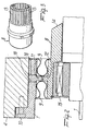
- Figure 1 is a schematic view of a conventional driving shaft 1, whose outer surface is machined so as to form a labyrinth-like profile 2 which accommodates the sealing device 3 having a complementarily shaped labyrinth-like profile and being rigidly coupled to the casing 4 of the motor.
- EP-A-0 472 929 discloses a sealing device for a refiner.
- the aim of the present invention is to provide a sealing device for explosion-proof motors which allows to maintain the free space between the casing and the driving shaft at a constant value which is equal to the minimum prescribed value.
- an object of the present invention is to provide a sealing device for explosion-proof motors which allows to maintain the free space between the casing and the shaft at a minimum value for any driving shaft size.
- Another object of the present invention is to provide a sealing device for explosion-proof motors which is highly reliable, relatively easy to manufacture and at low costs.
- the elastic means are provided for example by an elastic membrane which has an omega-shaped cross-section or is accordion-shaped or has any other suitable shape and is welded between the first and second elements.
- the teeth 11 and 12 are meant to constitute supporting elements for the elastic membranes 9 to relieve the stress that may act thereon in case of an explosion inside the casing 4 of the motor. In this case, the stress the elastic membranes 9 are subjected to is damped by their contact against the teeth 11 and 12.
- the teeth 11 and 12 can advantageously have a curved profile that matches the profile of the membranes 9 in order to extend the contact surface of the elastic membranes 9 if they are subjected to stress.
- the second element 8 is advantageously provided with a flared portion 14 which deflects upward the flame (which might have developed because of an internal explosion), reducing the possibility of said flame being guided into the free space between the second element 8 and the driving shaft 1, and thus constituting an additional safety in addition to the two-part configuration of the sealing device and to the cooling fins provided on the surface of the second element 8.
- the materials employed may be any according to requirements and to the state of the art.
Landscapes
- Engineering & Computer Science (AREA)
- Power Engineering (AREA)
- Motor Or Generator Frames (AREA)
- Gas-Insulated Switchgears (AREA)
- Glass Compositions (AREA)
Claims (10)
- Abdichtvorrichtung für explosionsgeschützte Motoren mit einem Motorgehäuse und einer Antriebswelle, die in dem Gehäuse drehbar ist, die ein erstes Element, das mit dem Motorgehäuse verbunden ist, ein zweites Element, das über Wälzmittel mit der Antriebswelle verbunden ist, einschließt, wobei die ersten und zweiten Element gegenseitig mittels elastischer Mittel verbunden sind, so dass ihre relative Bewegung möglich ist, dadurch gekennzeichnet, dass sie auf einer Oberfläche des zweiten Elements eine Vielzahl von längsverlaufenden Schlitzen aufweist, wobei die Schlitze eine Vielzahl von radial geneigten Finnen bilden, um Flammen zu kühlen und zu löschen.
- Abdichtvorrichtung nach Anspruch 1, dadurch gekennzeichnet, das die elastischen Mittel aus mindestens einer elastischen Membran bestehen, die starr mit dem ersten Element und dem zweiten Element verbunden ist.
- Abdichtvorrichtung nach Anspruch 2, dadurch gekennzeichnet, dass sie auf dem ersten und/oder dem zweiten Element einen Zahn aufweist, wobei der Zahn eine Anlagefläche für die elastische Membran nach Entstehung einer inneren Explosion bildet, die Druck auf die elastische Membran ausübt.
- Abdichtvorrichtung nach Anspruch 2, dadurch gekennzeichnet, dass sie zwei elastische Membrane umfasst, von denen jede mit den ersten und zweiten Elementen verbunden ist.
- Abdichtvorrichtung nach Anspruch 1, dadurch gekennzeichnet, dass das Wälzmittel ein Wälzlager umfasst, das unnachgiebig mit dem zweiten Element gekoppelt ist.
- Abdichtvorrichtung nach Anspruch 1, dadurch gekennzeichnet, dass sie ein Verbindungsmittel zum Verbinden des ersten Elements mit dem Gehäuse einschließt.
- Abdichtvorrichtung nach Anspruch 1, dadurch gekennzeichnet, dass das zweite Element eine Oberseite aufweist, die auf die Innenseite des Gehäuses gerichtet ist und geneigt ist, um die Flammen von dem freien Raum zwischen dem zweiten Element und der Antriebswelle abzulenken.
- Abdichtvorrichtung nach Anspruch 1, dadurch gekennzeichnet, dass sie einen freien Raum zwischen den elastischen Mitteln und den ersten und zweiten Elementen einschließt, wobei der freie Raum mit Füllmaterial gefüllt ist.
- Abdichtvorrichtung nach Anspruch 8, dadurch gekennzeichnet, dass sie zwei Befüllungs- und Abfuhrkanäle einschließt, die in dem ersten Element vorgesehen sind, um das Füllmaterial einzuführen und abzuführen.
- Abdichtvorrichtung nach Anspruch 1, dadurch gekennzeichnet, dass die mindestens eine elastische Membran aus Metall besteht.
Applications Claiming Priority (2)
| Application Number | Priority Date | Filing Date | Title |
|---|---|---|---|
| ITMI972111 | 1997-09-17 | ||
| IT97MI002111A IT1295022B1 (it) | 1997-09-17 | 1997-09-17 | Dispositivo di tenuta per motori antideflagranti |
Publications (3)
| Publication Number | Publication Date |
|---|---|
| EP0903834A2 EP0903834A2 (de) | 1999-03-24 |
| EP0903834A3 EP0903834A3 (de) | 2001-03-14 |
| EP0903834B1 true EP0903834B1 (de) | 2007-02-14 |
Family
ID=11377886
Family Applications (1)
| Application Number | Title | Priority Date | Filing Date |
|---|---|---|---|
| EP98203020A Expired - Lifetime EP0903834B1 (de) | 1997-09-17 | 1998-09-09 | Abdichtung für Explosionsgeschützte Motoren |
Country Status (4)
| Country | Link |
|---|---|
| US (1) | US6264204B1 (de) |
| EP (1) | EP0903834B1 (de) |
| DE (1) | DE69837065T2 (de) |
| IT (1) | IT1295022B1 (de) |
Families Citing this family (6)
| Publication number | Priority date | Publication date | Assignee | Title |
|---|---|---|---|---|
| US6747383B2 (en) | 2002-04-09 | 2004-06-08 | Honeywell International, Inc. | Generator with hydraulically mounted stator rotor |
| DE602006012842D1 (de) * | 2005-06-22 | 2010-04-22 | Itt Mfg Enterprises Inc | Vorrichtung für eine drehstopfbuchsendichtung |
| WO2008124522A2 (en) * | 2007-04-04 | 2008-10-16 | Biodel, Inc. | Amylin formulations |
| FR2915032B1 (fr) | 2007-04-12 | 2009-11-13 | Leroy Somer Moteurs | Machine tournante antideflagrante |
| DE102008007576A1 (de) * | 2008-02-05 | 2009-09-03 | Brose Fahrzeugteile GmbH & Co. Kommanditgesellschaft, Würzburg | Hohlwelleneinbaumotor zum Einbau in ein Gehäuse |
| EP3148055A1 (de) * | 2015-09-28 | 2017-03-29 | Siemens Aktiengesellschaft | Elektrische maschine, labyrinthdichtung für eine elektrische maschine und verfahren zum abdichten einer elektrischen maschine |
Family Cites Families (11)
| Publication number | Priority date | Publication date | Assignee | Title |
|---|---|---|---|---|
| DE2410692A1 (de) * | 1974-03-06 | 1975-09-11 | Knorr Bremse Gmbh | Halterung eines drehzahlgebers, insbesondere an einer fahrzeugradachse |
| DE2706511A1 (de) * | 1977-02-16 | 1978-08-17 | Hermetic Pumpen Gmbh | Spaltrohrmotorpumpenaggregat |
| GB1600515A (en) * | 1978-04-18 | 1981-10-14 | Glacier Metal Co Ltd | Annular seal |
| DE2901111A1 (de) * | 1979-01-12 | 1980-07-17 | Siemens Ag | Lagerschild |
| JPS59100128U (ja) * | 1982-12-23 | 1984-07-06 | 株式会社ニフコ | オイル式ダンパ− |
| DE3713921A1 (de) * | 1987-04-25 | 1988-11-10 | Flender A F & Co | Wellenabdichtung |
| CA1269693A (en) * | 1987-05-13 | 1990-05-29 | Robert Ross Hamilton | Explosion-proof electrical generator system |
| DE3804602A1 (de) * | 1988-02-13 | 1989-08-24 | Klein Schanzlin & Becker Ag | Explosionsgeschuetzter spaltrohrmotor |
| IT1221373B (it) * | 1988-04-29 | 1990-06-27 | Varvel Spa | Variatore di velocita' di tipo continuo |
| DE3834214A1 (de) * | 1988-10-07 | 1990-04-12 | Burgmann Dichtungswerk Feodor | Dichtung |
| EP0472929B1 (de) * | 1990-08-16 | 1995-03-01 | Voith Sulzer Stoffaufbereitung GmbH | Verwendung einer Dichtungsanordnung |
-
1997
- 1997-09-17 IT IT97MI002111A patent/IT1295022B1/it active IP Right Grant
-
1998
- 1998-09-09 DE DE69837065T patent/DE69837065T2/de not_active Expired - Lifetime
- 1998-09-09 EP EP98203020A patent/EP0903834B1/de not_active Expired - Lifetime
- 1998-09-11 US US09/151,586 patent/US6264204B1/en not_active Expired - Lifetime
Also Published As
| Publication number | Publication date |
|---|---|
| ITMI972111A1 (it) | 1999-03-17 |
| IT1295022B1 (it) | 1999-04-27 |
| EP0903834A3 (de) | 2001-03-14 |
| DE69837065T2 (de) | 2007-08-30 |
| DE69837065D1 (de) | 2007-03-29 |
| EP0903834A2 (de) | 1999-03-24 |
| US6264204B1 (en) | 2001-07-24 |
Similar Documents
| Publication | Publication Date | Title |
|---|---|---|
| US3756673A (en) | Stuffing box for a rotating shaft | |
| US3326453A (en) | Gas-bearing assembly | |
| US5395124A (en) | Retractible segmented packing ring for fluid turbines having gravity springs to neutralize packing segment weight forces | |
| EP0163450B1 (de) | Gleitringdichtung | |
| US3132906A (en) | Hydrodynamic devices | |
| CA2167424A1 (en) | Emission seal | |
| US5518256A (en) | Floating-ring seal | |
| GB1421540A (en) | Shaft bearing assemblies | |
| US5533739A (en) | Non-contacting seal with centering spring mounted in dovetailed grooved | |
| EP0903834B1 (de) | Abdichtung für Explosionsgeschützte Motoren | |
| KR870007532A (ko) | 원자로용 가스 순환기 및 그 이용방법 | |
| EP0921277A4 (de) | Dichtungsstruktur zwischen gasturbinenscheiben | |
| JPS6375396A (ja) | 多段式インライン渦巻ポンプ | |
| US3617068A (en) | Floating ring seal for rotating shafts | |
| EP0239519B1 (de) | Nutationsdämpfer | |
| US5582413A (en) | Oil seal for gas turbine | |
| US5356273A (en) | Radial bearing assembly for a high inertia flywheel of a canned pump | |
| US4685684A (en) | Dynamic seal | |
| US3767279A (en) | Flexible flange for bearings, preferably rolling bearings | |
| KR20000052393A (ko) | 대형 비틀림 진동 완충기 | |
| US4564500A (en) | Oil pot for reactor coolant pump motor and apparatus for controlling the oil level therein | |
| US4219310A (en) | Construction of adjustable blade shaft bearing in axial-flow fan with adjustable blades | |
| EP3234417B1 (de) | Lagerisolatordichtung mit verbesserter rotorantriebskupplung | |
| US3209183A (en) | Dynamoelectric machine | |
| US2996280A (en) | Heat shield |
Legal Events
| Date | Code | Title | Description |
|---|---|---|---|
| PUAI | Public reference made under article 153(3) epc to a published international application that has entered the european phase |
Free format text: ORIGINAL CODE: 0009012 |
|
| AK | Designated contracting states |
Kind code of ref document: A2 Designated state(s): DE FR GB IT |
|
| AX | Request for extension of the european patent |
Free format text: AL;LT;LV;MK;RO;SI |
|
| PUAL | Search report despatched |
Free format text: ORIGINAL CODE: 0009013 |
|
| AK | Designated contracting states |
Kind code of ref document: A3 Designated state(s): AT BE CH CY DE DK ES FI FR GB GR IE IT LI LU MC NL PT SE |
|
| AX | Request for extension of the european patent |
Free format text: AL;LT;LV;MK;RO;SI |
|
| 17P | Request for examination filed |
Effective date: 20010803 |
|
| AKX | Designation fees paid |
Free format text: DE FR GB IT |
|
| GRAP | Despatch of communication of intention to grant a patent |
Free format text: ORIGINAL CODE: EPIDOSNIGR1 |
|
| GRAS | Grant fee paid |
Free format text: ORIGINAL CODE: EPIDOSNIGR3 |
|
| GRAA | (expected) grant |
Free format text: ORIGINAL CODE: 0009210 |
|
| RAP1 | Party data changed (applicant data changed or rights of an application transferred) |
Owner name: SOICO SUD SOCIETA IMPIANTISTICA E COSTRUZIONI S.P. |
|
| RAP1 | Party data changed (applicant data changed or rights of an application transferred) |
Owner name: ABB SACE S.P.A. |
|
| AK | Designated contracting states |
Kind code of ref document: B1 Designated state(s): DE FR GB IT |
|
| REG | Reference to a national code |
Ref country code: GB Ref legal event code: FG4D |
|
| REF | Corresponds to: |
Ref document number: 69837065 Country of ref document: DE Date of ref document: 20070329 Kind code of ref document: P |
|
| ET | Fr: translation filed | ||
| PLBE | No opposition filed within time limit |
Free format text: ORIGINAL CODE: 0009261 |
|
| STAA | Information on the status of an ep patent application or granted ep patent |
Free format text: STATUS: NO OPPOSITION FILED WITHIN TIME LIMIT |
|
| 26N | No opposition filed |
Effective date: 20071115 |
|
| GBPC | Gb: european patent ceased through non-payment of renewal fee |
Effective date: 20070909 |
|
| PG25 | Lapsed in a contracting state [announced via postgrant information from national office to epo] |
Ref country code: GB Free format text: LAPSE BECAUSE OF NON-PAYMENT OF DUE FEES Effective date: 20070909 |
|
| REG | Reference to a national code |
Ref country code: FR Ref legal event code: TP |
|
| REG | Reference to a national code |
Ref country code: FR Ref legal event code: PLFP Year of fee payment: 19 |
|
| PGFP | Annual fee paid to national office [announced via postgrant information from national office to epo] |
Ref country code: DE Payment date: 20160921 Year of fee payment: 19 |
|
| PGFP | Annual fee paid to national office [announced via postgrant information from national office to epo] |
Ref country code: FR Payment date: 20160921 Year of fee payment: 19 |
|
| PGFP | Annual fee paid to national office [announced via postgrant information from national office to epo] |
Ref country code: IT Payment date: 20160922 Year of fee payment: 19 |
|
| REG | Reference to a national code |
Ref country code: DE Ref legal event code: R119 Ref document number: 69837065 Country of ref document: DE |
|
| REG | Reference to a national code |
Ref country code: FR Ref legal event code: ST Effective date: 20180531 |
|
| PG25 | Lapsed in a contracting state [announced via postgrant information from national office to epo] |
Ref country code: DE Free format text: LAPSE BECAUSE OF NON-PAYMENT OF DUE FEES Effective date: 20180404 |
|
| PG25 | Lapsed in a contracting state [announced via postgrant information from national office to epo] |
Ref country code: FR Free format text: LAPSE BECAUSE OF NON-PAYMENT OF DUE FEES Effective date: 20171002 Ref country code: IT Free format text: LAPSE BECAUSE OF NON-PAYMENT OF DUE FEES Effective date: 20170909 |