EP0447658A2 - Siège de véhicule - Google Patents
Siège de véhicule Download PDFInfo
- Publication number
- EP0447658A2 EP0447658A2 EP90124880A EP90124880A EP0447658A2 EP 0447658 A2 EP0447658 A2 EP 0447658A2 EP 90124880 A EP90124880 A EP 90124880A EP 90124880 A EP90124880 A EP 90124880A EP 0447658 A2 EP0447658 A2 EP 0447658A2
- Authority
- EP
- European Patent Office
- Prior art keywords
- shaft
- bearings
- bearing
- vehicle seat
- height adjustment
- Prior art date
- Legal status (The legal status is an assumption and is not a legal conclusion. Google has not performed a legal analysis and makes no representation as to the accuracy of the status listed.)
- Withdrawn
Links
- 230000000149 penetrating effect Effects 0.000 claims description 2
- 238000005452 bending Methods 0.000 description 4
- 230000002349 favourable effect Effects 0.000 description 4
- 238000004873 anchoring Methods 0.000 description 2
- 230000005540 biological transmission Effects 0.000 description 2
- 238000010276 construction Methods 0.000 description 2
- 239000000463 material Substances 0.000 description 2
- 238000000034 method Methods 0.000 description 2
- 230000001360 synchronised effect Effects 0.000 description 2
- 238000010521 absorption reaction Methods 0.000 description 1
- 230000015572 biosynthetic process Effects 0.000 description 1
- 230000000694 effects Effects 0.000 description 1
- 238000009434 installation Methods 0.000 description 1
- 238000005461 lubrication Methods 0.000 description 1
- 238000004519 manufacturing process Methods 0.000 description 1
- 239000004033 plastic Substances 0.000 description 1
- -1 polytetrafluoroethylene Polymers 0.000 description 1
- 229920001343 polytetrafluoroethylene Polymers 0.000 description 1
- 239000004810 polytetrafluoroethylene Substances 0.000 description 1
- 238000003860 storage Methods 0.000 description 1
Images

Classifications
-
- B—PERFORMING OPERATIONS; TRANSPORTING
- B60—VEHICLES IN GENERAL
- B60N—SEATS SPECIALLY ADAPTED FOR VEHICLES; VEHICLE PASSENGER ACCOMMODATION NOT OTHERWISE PROVIDED FOR
- B60N2/00—Seats specially adapted for vehicles; Arrangement or mounting of seats in vehicles
- B60N2/02—Seats specially adapted for vehicles; Arrangement or mounting of seats in vehicles the seat or part thereof being movable, e.g. adjustable
- B60N2/0224—Non-manual adjustments, e.g. with electrical operation
- B60N2/02246—Electric motors therefor
-
- B—PERFORMING OPERATIONS; TRANSPORTING
- B60—VEHICLES IN GENERAL
- B60N—SEATS SPECIALLY ADAPTED FOR VEHICLES; VEHICLE PASSENGER ACCOMMODATION NOT OTHERWISE PROVIDED FOR
- B60N2/00—Seats specially adapted for vehicles; Arrangement or mounting of seats in vehicles
- B60N2/02—Seats specially adapted for vehicles; Arrangement or mounting of seats in vehicles the seat or part thereof being movable, e.g. adjustable
- B60N2/04—Seats specially adapted for vehicles; Arrangement or mounting of seats in vehicles the seat or part thereof being movable, e.g. adjustable the whole seat being movable
- B60N2/16—Seats specially adapted for vehicles; Arrangement or mounting of seats in vehicles the seat or part thereof being movable, e.g. adjustable the whole seat being movable height-adjustable
- B60N2/1605—Seats specially adapted for vehicles; Arrangement or mounting of seats in vehicles the seat or part thereof being movable, e.g. adjustable the whole seat being movable height-adjustable characterised by the cinematic
- B60N2/161—Rods
- B60N2/1615—Parallelogram-like structure
-
- B—PERFORMING OPERATIONS; TRANSPORTING
- B60—VEHICLES IN GENERAL
- B60N—SEATS SPECIALLY ADAPTED FOR VEHICLES; VEHICLE PASSENGER ACCOMMODATION NOT OTHERWISE PROVIDED FOR
- B60N2/00—Seats specially adapted for vehicles; Arrangement or mounting of seats in vehicles
- B60N2/02—Seats specially adapted for vehicles; Arrangement or mounting of seats in vehicles the seat or part thereof being movable, e.g. adjustable
- B60N2/04—Seats specially adapted for vehicles; Arrangement or mounting of seats in vehicles the seat or part thereof being movable, e.g. adjustable the whole seat being movable
- B60N2/16—Seats specially adapted for vehicles; Arrangement or mounting of seats in vehicles the seat or part thereof being movable, e.g. adjustable the whole seat being movable height-adjustable
- B60N2/1635—Seats specially adapted for vehicles; Arrangement or mounting of seats in vehicles the seat or part thereof being movable, e.g. adjustable the whole seat being movable height-adjustable characterised by the drive mechanism
- B60N2/164—Linear actuator, e.g. screw mechanism
Definitions
- the invention relates to a vehicle seat which is adjustable and fixable to and fro by means of a sled-shaped seat length adjuster on rails or the like arranged in the direction of travel and which has an angle and / or height adjustable support device for the seat surface on the adjuster, with parallel to one another , in the use position oriented in the direction of travel, beams or the like, each with mutually opposite and aligned bearings for rotatable and pivotable or displaceable adjusting means, parts and / or guide elements between the adjuster and carrying device for their height adjustment.
- Such vehicle seats are known in particular for passenger cars in a variety of designs.
- height adjustment of such seats has also been known for some time, since smaller people can reach the controls sufficiently well from a position that is only moved forward, but still have an unsatisfactory view.
- supports or spars of the adjuster on the one hand and the support device of the actual seat on the other hand are known at the same time penetrating pivot bolts which each penetrate holes in the supports mentioned and are riveted on both sides of their bearing point, for example.
- these axis-like bolts pass through a carrier and, on the other hand, a swivel lever, through the pivoting of which the desired height adjustment can then be carried out.
- the invention is therefore based on the object of providing a vehicle seat of the type mentioned at the outset which has practically play-free storage with a long service life, if possible also with the service life of the vehicle seat itself has a corresponding lifespan.
- the surprising solution to this apparently unsolvable task consists essentially in the fact that, as the adjustment part rotatable for the height adjustment on the bearings, the bearing axles of bearings that are aligned with one another are accommodated in each case in an inner recess, with adjustment means for the height adjustment and / or for the guidance or firmly connected shaft is provided, which runs continuously over the entire distance of the aligned bearings and is mounted on both bearings.
- Each of the bearings thus has a shaft which is supported on at least two sides and is therefore subjected to practically no bending moment.
- the number of bearing points does not need to be increased, since only one bearing point is required for this shaft at each bearing.
- the respective aligned warehouse thus serves as a second warehouse for his counterpart.
- the shaft has the advantages of any shaft that is tensioned or supported on both sides and is subject to considerably less wear than a shaft or axis mounted on one side.
- an adjustment drive for example a manual drive or a motor with gear and pivot lever, which in turn can pivot, engages on the outside of the continuous shaft for the height adjustment are connected to the counterpart changing its distance during the height adjustment.
- the continuous shaft which can be rotated for the height adjustment, can be mounted on the seat support device and fastened to the counter-seat adjuster arranged with levers or the like, or the shaft can be mounted on the adjuster and by means of levers or the like be connected to the height-adjustable carrying device.
- the latter is the often simpler solution because the drive means can then also be arranged largely stationary on the longitudinal adjuster.
- the shaft which has central inner recesses and connects two aligned bearings, is a hollow shaft, preferably a tube.
- the inner recesses are also continuous. This not only saves weight, but also lowers the manufacturing price of the shaft.
- an embodiment of the invention of very considerable advantage is made possible, which can consist in the fact that the axes of the two shaft bearings, which accommodate the hollow shaft, are guided through the entire hollow shaft and are integrally connected to one another. This then results not only for the shaft but also for the axis that enables the rotation and mounting of the shaft to be clamped on both sides of the opposite bearing, which further increases the resistance to transverse forces and vibrations and the like during driving.
- a combination of a continuous axis and a continuous shaft mounted thereon with favorable dimensions and material pairing, allows a very long freedom from play or a long service life of an original selected game, which can be chosen so small that a vehicle seat can not make relative wobbling movements relative to its anchoring.
- Embodiments of the vehicle seat according to the invention and, in particular, of its bearings used for height adjustment are the subject of claims 6 to 10.
- Claim 6 specifies mounting options for the continuous axis, which either allows their disassembly or a particularly good, yet inexpensive fixation.
- the measures of claim 7 improve the relative rotatability of the shaft on the axis, which need not necessarily have contact with the axis over its entire length.
- Bearing bushes that is, plain bearings, which require little space in the radial direction are proposed.
- inexpensive material pairings and bearings can be selected that do not require lubrication and are still easy to move.
- bearing bushes made of polytetrafluoroethylene or with a covering made of this plastic can be selected
- Claims 8 and 9 relate to measures which can transmit the movement of the hollow shaft to the adjusting elements used for height adjustment, in particular swivel levers and to the bearing located on the counterpart adjusted in the process.
- Claim 10 specifies a size relation of the bearings formed by the continuous shaft according to the invention on the one hand and their diameter, which results in the favorable conditions for absorbing dynamic forces during driving operation while avoiding a gradual deflection of the bearings.
- the height adjustment is inexpensive and the bearings of the height adjustment are designed so that they keep their play as long as possible over a long life, if possible the entire life of the seat or the tendency of the vehicle seat to wobble relative to its anchoring on poor paths is avoided for a long service life.
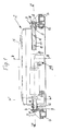
- the substructure 2 also includes an angle and / or height adjustable support device 5 for the actual seat or seat 6.
- This support device 5 is height-adjustable in the manner to be described on the adjuster 3 and can be fixed at different heights.
- the vehicle seat 1 can be adjusted not only in its distance to a steering wheel of a vehicle, but also in its height and possibly with respect to the inclination of the seat surface 6.
- the also possible adjustment of the inclination of the backrest 7 can be done in a known manner.
- FIGS. 1 and 2 it can be seen that on supports 8, spars or the like which run parallel to one another and are oriented in the direction of travel in the position of use in each case at a distance from one another and in alignment with one another, bearings 9 for rotatable and pivotable or to be described in more detail displaceable adjusting means, parts and / or guide elements are arranged between the adjuster 3 and the carrying device 5 for their height adjustment.
- 3 shows that two such pairs of mutually aligned bearings 9 - in the exemplary embodiment on the adjuster 3 and its supports 8 - are arranged.
- the bearing axles 10 of bearings 9 that are aligned with one another are accommodated in each case in an inner recess 11 or inner longitudinal cavity, with adjusting means, in the exemplary embodiment pivoting levers 12, for the height adjustment and / or provided for guiding in a form-fitting or firmly connected shaft 13, which runs continuously over the entire distance between the aligned bearings 9 and is supported on both bearings 9.
- the shaft 13 also serves for formation both aligned bearings 9 and can also drive a pivot lever 12 on each of their two bearings 9 and thus not only better transmit the forces occurring due to their double-sided mounting and bring about greater stability and rigidity, but also the adjusting forces more evenly on the relative to the bearings 9 adjustable part, the carrying device 5 in the exemplary embodiment, so that even with this adjustment movement no bending moments occur which overload the bearings so that they are gradually knocked out or their play increases too quickly.
- the driving force for the height adjustment via the continuous shaft 13 is passed on synchronously and at the same time to both aligned bearings and thus the adjustment process is carried out without the risk of tilting, so that, even under a one-sided introduction of the adjustment forces, lower forces may be required for the adjustment is sufficient.
- an adjustment drive 14 engages, which can be, for example, a manual drive or a motor with a transmission and can transmit its adjustment movement to the shaft 13 via the same pivoting lever 12, which also engages the height-adjustable part by means of a further section.
- a manual drive or a motor with a transmission can be, for example, a manual drive or a motor with a transmission and can transmit its adjustment movement to the shaft 13 via the same pivoting lever 12, which also engages the height-adjustable part by means of a further section.
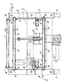
- these approximately triangular swivel levers 12 can be clearly seen, which have an approximately right-angled triangular shape, the bearings 9 being arranged approximately in the region of the right angle, while the drive 14 is located at a fastening point 15 located below the bearings 9 can attack directly or via transmission linkage, while finally a second, in the middle height position shown in Fig.2 approximately at the same height as the bearing 9 bearing 16 by the rotation of the shaft 13 in the direction of the double arrow Pf 1 can be pivoted up and down and is attached to the support device 5 so that it is pivoted accordingly higher or lower. If a pan is synchronized performed all pivot levers 12, this means a height adjustment of the seat 6, but if only one shaft 13 is rotated and thus only one pair of pivot levers is moved, the inclination of the seat 6 can be adjusted.
- this shaft is a hollow shaft, preferably a tube . This is made possible by the embodiment shown in FIG. 1, according to which the axes 10 of two aligned bearings 9 receiving this hollow shaft are also guided through the entire hollow shaft and are connected to one another in one piece.
- the bearing axles contribute to the mutual support and stiffening of the two aligned bearings 9 to a considerable extent, so that dynamic transverse forces, oscillating movements and also the adjusting forces cannot bring about any noteworthy deformations on the bearings 9 and therefore no precautions are required to absorb large clamping moments.
- the bearings 9 are spared excessive wear so that they meet the tolerances chosen in the design and maintain practical freedom of play over a long service life.
- the axis 10 passing through two bearings 9 is fastened in the exemplary embodiment on the end face by means of head screws 17 passing through the outside of the respective carrier 8 of the adjuster 3 - in a modified embodiment of the carrying device 5, so that disassembly is also possible. If such a disassembly, which is hardly necessary due to the long service life of the bearings 9, is not to be carried out, the axis 10 could also be non-detachably connected, for example welded, to the supports 8, which simplifies and reduces the overall cost.
- Fig.1 can also be seen for one of the two shafts 13 for the height adjustment that between the through axis 10 and the continuous, serving as shaft 13 tube adjacent to the attachment of the axis 10 at both bearings bearing bushings 18 are provided, which in their axial extent preferably extend at least to the point of attack of the actuating or pivoting lever 12, drive lever or the like.
- this area which transmits the adjusting forces, the bearing between hollow shaft 13 and axis 10 is effected, while there may be a distance over the remaining length area between shaft 13 and axis 10.
- the pivot levers 12 have the shape of right-angled triangles in the exemplary embodiment.
- Fig. 3 it can be seen that the two pivot levers 12 fastened on a shaft 13 are fastened to bearings 16 which engage the adjustable part, that is to say in the embodiment of the carrying device 5, which in turn are braced against one another by a continuous shaft 21 and / or axis 22 and can be supported, but in the exemplary embodiment according to FIG. 3 this is only achieved with such a shaft 21, while the shaft and axis arranged parallel to it are interrupted, since they would otherwise be moved downward with the drive 23 for the longitudinal adjustment of the vehicle seat 1 would collide.
- the total length of the bearing or bearing pair formed from the shaft and axis is therefore several times larger than the diameter of the bearing or of the shaft and axis in the bearing area, for example about twenty to forty times, in particular thirty times longer than the diameter of the bearing, which gives the favorable conditions in the The result is the absorption of forces without increasing the bearing play.
- a height adjustment of a carrying device 5 is also provided relative to this adjuster 3, the carrying device 5 carrying the actual seat surface 6 and the backrest 7.
- two spaced-apart pairs of bearings 9 are provided, the axes of rotation of which are aligned with one another, with bearing axles 10 being provided on these bearings, which engage in inner recesses 11 of a shaft 13, which extend continuously over the entire distance from such aligned bearings 9 runs and is mounted on both bearings 9.
- the corresponding adjustment means preferably swivel levers 12, act on the shaft 13 on the one hand for the rotary drive of the shaft 13 and on the other hand for the height adjustment. Since the shaft of each bearing for the height adjustment is thus mounted on both sides, the forces which occur can be introduced more cheaply, so that an increase in the bearing play or the creation of a game on the originally play-free bearings does not occur or only after a very long service life.
Landscapes
- Engineering & Computer Science (AREA)
- Aviation & Aerospace Engineering (AREA)
- Transportation (AREA)
- Mechanical Engineering (AREA)
- Seats For Vehicles (AREA)
Applications Claiming Priority (2)
| Application Number | Priority Date | Filing Date | Title |
|---|---|---|---|
| DE4009212 | 1990-03-22 | ||
| DE4009212A DE4009212A1 (de) | 1990-03-22 | 1990-03-22 | Fahrzeugsitz |
Publications (2)
| Publication Number | Publication Date |
|---|---|
| EP0447658A2 true EP0447658A2 (fr) | 1991-09-25 |
| EP0447658A3 EP0447658A3 (en) | 1992-01-15 |
Family
ID=6402816
Family Applications (1)
| Application Number | Title | Priority Date | Filing Date |
|---|---|---|---|
| EP19900124880 Withdrawn EP0447658A3 (en) | 1990-03-22 | 1990-12-20 | Vehicle seat |
Country Status (2)
| Country | Link |
|---|---|
| EP (1) | EP0447658A3 (fr) |
| DE (1) | DE4009212A1 (fr) |
Cited By (3)
| Publication number | Priority date | Publication date | Assignee | Title |
|---|---|---|---|---|
| WO1997046412A1 (fr) * | 1996-06-06 | 1997-12-11 | Lear Corporation | Dispositif de reglage de siege de vehicule actionne par moteur, a element d'ecartement/douille de tube de torsion monobloc |
| WO1997046411A1 (fr) * | 1996-06-06 | 1997-12-11 | Lear Corporation | Dispositif de reglage de siege de vehicule actionne par moteur a actionnement par vis de commande horizontale et centrale |
| EP2383144A3 (fr) * | 2010-04-28 | 2014-03-12 | Aguti Produktentwicklung & Design Gmbh | Dispositif de liaison d'un siège de véhicule sur une unité rotative, unité rotative et siège de véhicule |
Family Cites Families (12)
| Publication number | Priority date | Publication date | Assignee | Title |
|---|---|---|---|---|
| BE540235A (fr) * | 1953-12-16 | |||
| US2907371A (en) * | 1954-04-26 | 1959-10-06 | American Forging & Socket Co | Adjustable seat track assembly |
| US2905228A (en) * | 1955-07-11 | 1959-09-22 | American Metal Prod | Seat supporting and adjusting mechanism |
| US2839124A (en) * | 1956-01-16 | 1958-06-17 | Houdaille Industries Inc | Multi-motion seat adjuster with multiple drive motors |
| GB926540A (en) * | 1961-01-19 | 1963-05-22 | Hallam Sleigh & Cheston Ltd | Improvements in vehicle seats |
| DE6930907U (de) * | 1969-08-01 | 1969-11-20 | Isringhausen Geb | Hoehen- und neigungsverstellbarer fahrzeugsitz |
| FR2191702A5 (fr) * | 1972-06-27 | 1974-02-01 | Sable Freres Int | |
| DE2527047C2 (de) * | 1975-06-18 | 1986-09-11 | Franz Kiel GmbH, 8860 Nördlingen | Kraftfahrzeugsitz, insbesondere Fahrersitz |
| ZA777675B (en) * | 1977-02-04 | 1978-10-25 | Turner Willenhall Ltd H R | Seat height adjustment mechanism |
| DE2851562A1 (de) * | 1978-11-29 | 1980-06-12 | Rentrop Hubbert & Wagner | Sitz, insbesondere kraftfahrzeugsitz |
| DE2901208C2 (de) * | 1979-01-13 | 1984-08-09 | Keiper Automobiltechnik Gmbh & Co Kg, 5630 Remscheid | Verstellbarer Sitz, insbesondere Fahrzeugsitz |
| DE3224251A1 (de) * | 1982-06-28 | 1983-12-29 | Alfred Teves Gmbh, 6000 Frankfurt | Instrumententraeger fuer einen elektromotorisch verstellbaren fahrzeugsitz |
-
1990
- 1990-03-22 DE DE4009212A patent/DE4009212A1/de not_active Withdrawn
- 1990-12-20 EP EP19900124880 patent/EP0447658A3/de not_active Withdrawn
Cited By (5)
| Publication number | Priority date | Publication date | Assignee | Title |
|---|---|---|---|---|
| WO1997046412A1 (fr) * | 1996-06-06 | 1997-12-11 | Lear Corporation | Dispositif de reglage de siege de vehicule actionne par moteur, a element d'ecartement/douille de tube de torsion monobloc |
| WO1997046411A1 (fr) * | 1996-06-06 | 1997-12-11 | Lear Corporation | Dispositif de reglage de siege de vehicule actionne par moteur a actionnement par vis de commande horizontale et centrale |
| US5797576A (en) * | 1996-06-06 | 1998-08-25 | Lear Corporation | Vehicle power seat adjuster with center horizontal drive screw actuation |
| US5871195A (en) * | 1996-06-06 | 1999-02-16 | Lear Corporation | Vehicle power seat adjuster with one piece torsion tube bushing/spacer |
| EP2383144A3 (fr) * | 2010-04-28 | 2014-03-12 | Aguti Produktentwicklung & Design Gmbh | Dispositif de liaison d'un siège de véhicule sur une unité rotative, unité rotative et siège de véhicule |
Also Published As
| Publication number | Publication date |
|---|---|
| DE4009212A1 (de) | 1991-09-26 |
| EP0447658A3 (en) | 1992-01-15 |
Similar Documents
| Publication | Publication Date | Title |
|---|---|---|
| DE19646470B4 (de) | Kraftfahrzeugsitz mit einer Lehne und einem Sitz | |
| DE3221959C2 (de) | Sitzschiene für Fahrzeugsitze | |
| EP3511201B1 (fr) | Dispositif de réglage destiné au réglage longitidunal d'un siège de véhicule | |
| EP1243461B1 (fr) | Chassis d'assise de siège pour un siège de véhicule | |
| EP1832467A2 (fr) | Siège de véhicule, en particulier siège de véhicule automobile | |
| EP0983196A1 (fr) | Vehicule de remorquage pour avions | |
| EP1176048A1 (fr) | Siège de véhicule avec assise réglable en inclinaison | |
| DE2844647C2 (de) | Längsverstellvorrichtung für einen Fahrzeugsitz, insbesondere einen Kraftfahrzeugsitz | |
| DE102004055643B4 (de) | Verfahren zur Sitzverstellung und Sitz | |
| EP1989963B1 (fr) | Siège doté d'une assise et d'un dossier | |
| DE69127909T2 (de) | Schiebe-Hebe-Dach-Vorrichtung für Kraftfahrzeug | |
| EP0111674A2 (fr) | Siège, en particulier pour une voiture automobile | |
| DE102017215910A1 (de) | Sitz für ein Kraftfahrzeug | |
| DE2715547A1 (de) | Kombinierte hoehen-laengsverstellvorrichtung fuer fahrzeugsitze | |
| EP0568900B1 (fr) | Système à deux glissières de forme en U à encombrement réduit, en particulier pour sièges de véhicules automobiles | |
| EP0447658A2 (fr) | Siège de véhicule | |
| DE102012108641B4 (de) | Sitz mit einer Arretierungseinrichtung | |
| DE102010042881B4 (de) | Fahrzeugsitz mit einer Sitztiefenverstelleinrichtung | |
| DE2004504B2 (de) | Längsverstelleinrichtung für Fahrzeugsitze | |
| DE102005022694B4 (de) | Sitz | |
| DE2740268A1 (de) | Fahrzeugsitz | |
| DE102015111844A1 (de) | Passagiersitz für ein Luftfahrzeug | |
| DE68923174T2 (de) | Anordnung für fahrzeugsitze. | |
| DE3426265A1 (de) | Kraftfahrzeugsitz | |
| EP1046538A2 (fr) | Siège de véhicule, en particulier siège d'automobile |
Legal Events
| Date | Code | Title | Description |
|---|---|---|---|
| PUAI | Public reference made under article 153(3) epc to a published international application that has entered the european phase |
Free format text: ORIGINAL CODE: 0009012 |
|
| AK | Designated contracting states |
Kind code of ref document: A2 Designated state(s): AT BE CH DE DK ES FR GB GR IT LI LU NL SE |
|
| PUAL | Search report despatched |
Free format text: ORIGINAL CODE: 0009013 |
|
| AK | Designated contracting states |
Kind code of ref document: A3 Designated state(s): AT BE CH DE DK ES FR GB GR IT LI LU NL SE |
|
| 17P | Request for examination filed |
Effective date: 19920205 |
|
| 17Q | First examination report despatched |
Effective date: 19930428 |
|
| STAA | Information on the status of an ep patent application or granted ep patent |
Free format text: STATUS: THE APPLICATION IS DEEMED TO BE WITHDRAWN |
|
| 18D | Application deemed to be withdrawn |
Effective date: 19940407 |