EP0447025B1 - Magnetischer Aufzeichnungsträger und Verfahren zu seiner Herstellung - Google Patents
Magnetischer Aufzeichnungsträger und Verfahren zu seiner Herstellung Download PDFInfo
- Publication number
- EP0447025B1 EP0447025B1 EP91300614A EP91300614A EP0447025B1 EP 0447025 B1 EP0447025 B1 EP 0447025B1 EP 91300614 A EP91300614 A EP 91300614A EP 91300614 A EP91300614 A EP 91300614A EP 0447025 B1 EP0447025 B1 EP 0447025B1
- Authority
- EP
- European Patent Office
- Prior art keywords
- substrate
- depressions
- head
- nominal
- magnetizable
- Prior art date
- Legal status (The legal status is an assumption and is not a legal conclusion. Google has not performed a legal analysis and makes no representation as to the accuracy of the status listed.)
- Expired - Lifetime
Links
- 238000000034 method Methods 0.000 title claims description 27
- 238000004519 manufacturing process Methods 0.000 title claims description 6
- 239000000758 substrate Substances 0.000 claims description 64
- 230000002463 transducing effect Effects 0.000 claims description 35
- 229910045601 alloy Inorganic materials 0.000 claims description 27
- 239000000956 alloy Substances 0.000 claims description 27
- XAGFODPZIPBFFR-UHFFFAOYSA-N aluminium Chemical compound [Al] XAGFODPZIPBFFR-UHFFFAOYSA-N 0.000 claims description 19
- 229910052782 aluminium Inorganic materials 0.000 claims description 19
- 239000004411 aluminium Substances 0.000 claims description 17
- 238000013500 data storage Methods 0.000 claims description 15
- 239000000463 material Substances 0.000 claims description 7
- 230000003746 surface roughness Effects 0.000 claims description 7
- 230000001133 acceleration Effects 0.000 claims description 6
- 238000000151 deposition Methods 0.000 claims description 5
- 230000001681 protective effect Effects 0.000 claims description 5
- 238000012876 topography Methods 0.000 claims description 4
- 238000003860 storage Methods 0.000 claims description 3
- 238000006073 displacement reaction Methods 0.000 claims description 2
- 238000007747 plating Methods 0.000 claims description 2
- 230000003362 replicative effect Effects 0.000 claims 2
- 230000001419 dependent effect Effects 0.000 claims 1
- 239000010410 layer Substances 0.000 description 58
- PXHVJJICTQNCMI-UHFFFAOYSA-N Nickel Chemical compound [Ni] PXHVJJICTQNCMI-UHFFFAOYSA-N 0.000 description 6
- 238000013459 approach Methods 0.000 description 6
- 239000004744 fabric Substances 0.000 description 6
- 238000010304 firing Methods 0.000 description 5
- 238000012360 testing method Methods 0.000 description 5
- VYZAMTAEIAYCRO-UHFFFAOYSA-N Chromium Chemical compound [Cr] VYZAMTAEIAYCRO-UHFFFAOYSA-N 0.000 description 4
- 239000000314 lubricant Substances 0.000 description 4
- 238000005498 polishing Methods 0.000 description 4
- 229910052804 chromium Inorganic materials 0.000 description 3
- 239000011651 chromium Substances 0.000 description 3
- ZGDWHDKHJKZZIQ-UHFFFAOYSA-N cobalt nickel Chemical compound [Co].[Ni].[Ni].[Ni] ZGDWHDKHJKZZIQ-UHFFFAOYSA-N 0.000 description 3
- BHEPBYXIRTUNPN-UHFFFAOYSA-N hydridophosphorus(.) (triplet) Chemical compound [PH] BHEPBYXIRTUNPN-UHFFFAOYSA-N 0.000 description 3
- 239000007788 liquid Substances 0.000 description 3
- 229910052759 nickel Inorganic materials 0.000 description 3
- OKTJSMMVPCPJKN-UHFFFAOYSA-N Carbon Chemical compound [C] OKTJSMMVPCPJKN-UHFFFAOYSA-N 0.000 description 2
- WAIPAZQMEIHHTJ-UHFFFAOYSA-N [Cr].[Co] Chemical compound [Cr].[Co] WAIPAZQMEIHHTJ-UHFFFAOYSA-N 0.000 description 2
- 229910052799 carbon Inorganic materials 0.000 description 2
- 238000000576 coating method Methods 0.000 description 2
- 239000012634 fragment Substances 0.000 description 2
- 238000007373 indentation Methods 0.000 description 2
- 230000007774 longterm Effects 0.000 description 2
- 230000003287 optical effect Effects 0.000 description 2
- 239000011241 protective layer Substances 0.000 description 2
- HBMJWWWQQXIZIP-UHFFFAOYSA-N silicon carbide Chemical compound [Si+]#[C-] HBMJWWWQQXIZIP-UHFFFAOYSA-N 0.000 description 2
- 239000000725 suspension Substances 0.000 description 2
- 229910000684 Cobalt-chrome Inorganic materials 0.000 description 1
- 229910000990 Ni alloy Inorganic materials 0.000 description 1
- 238000004140 cleaning Methods 0.000 description 1
- 239000011248 coating agent Substances 0.000 description 1
- 239000010952 cobalt-chrome Substances 0.000 description 1
- 230000000052 comparative effect Effects 0.000 description 1
- 239000012141 concentrate Substances 0.000 description 1
- 238000001816 cooling Methods 0.000 description 1
- 238000005260 corrosion Methods 0.000 description 1
- 230000007797 corrosion Effects 0.000 description 1
- 238000005520 cutting process Methods 0.000 description 1
- 230000003247 decreasing effect Effects 0.000 description 1
- 238000013461 design Methods 0.000 description 1
- 230000000694 effects Effects 0.000 description 1
- NBVXSUQYWXRMNV-UHFFFAOYSA-N fluoromethane Chemical compound FC NBVXSUQYWXRMNV-UHFFFAOYSA-N 0.000 description 1
- 239000002223 garnet Substances 0.000 description 1
- 238000007689 inspection Methods 0.000 description 1
- 230000001788 irregular Effects 0.000 description 1
- 238000003754 machining Methods 0.000 description 1
- 238000002844 melting Methods 0.000 description 1
- 230000008018 melting Effects 0.000 description 1
- 239000002245 particle Substances 0.000 description 1
- 239000011253 protective coating Substances 0.000 description 1
- 230000005855 radiation Effects 0.000 description 1
- 239000000523 sample Substances 0.000 description 1
- 229910010271 silicon carbide Inorganic materials 0.000 description 1
- 239000002002 slurry Substances 0.000 description 1
- 239000007787 solid Substances 0.000 description 1
- 239000002904 solvent Substances 0.000 description 1
- 238000004528 spin coating Methods 0.000 description 1
- 238000009987 spinning Methods 0.000 description 1
- 238000013519 translation Methods 0.000 description 1
- 238000009966 trimming Methods 0.000 description 1
- 238000001771 vacuum deposition Methods 0.000 description 1
Images
Classifications
-
- G—PHYSICS
- G11—INFORMATION STORAGE
- G11B—INFORMATION STORAGE BASED ON RELATIVE MOVEMENT BETWEEN RECORD CARRIER AND TRANSDUCER
- G11B23/00—Record carriers not specific to the method of recording or reproducing; Accessories, e.g. containers, specially adapted for co-operation with the recording or reproducing apparatus ; Intermediate mediums; Apparatus or processes specially adapted for their manufacture
- G11B23/50—Reconditioning of record carriers; Cleaning of record carriers ; Carrying-off electrostatic charges
- G11B23/505—Reconditioning of record carriers; Cleaning of record carriers ; Carrying-off electrostatic charges of disk carriers
-
- G—PHYSICS
- G11—INFORMATION STORAGE
- G11B—INFORMATION STORAGE BASED ON RELATIVE MOVEMENT BETWEEN RECORD CARRIER AND TRANSDUCER
- G11B5/00—Recording by magnetisation or demagnetisation of a record carrier; Reproducing by magnetic means; Record carriers therefor
- G11B5/48—Disposition or mounting of heads or head supports relative to record carriers ; arrangements of heads, e.g. for scanning the record carrier to increase the relative speed
- G11B5/58—Disposition or mounting of heads or head supports relative to record carriers ; arrangements of heads, e.g. for scanning the record carrier to increase the relative speed with provision for moving the head for the purpose of maintaining alignment of the head relative to the record carrier during transducing operation, e.g. to compensate for surface irregularities of the latter or for track following
- G11B5/60—Fluid-dynamic spacing of heads from record-carriers
- G11B5/6005—Specially adapted for spacing from a rotating disc using a fluid cushion
- G11B5/6082—Design of the air bearing surface
-
- G—PHYSICS
- G11—INFORMATION STORAGE
- G11B—INFORMATION STORAGE BASED ON RELATIVE MOVEMENT BETWEEN RECORD CARRIER AND TRANSDUCER
- G11B5/00—Recording by magnetisation or demagnetisation of a record carrier; Reproducing by magnetic means; Record carriers therefor
- G11B5/74—Record carriers characterised by the form, e.g. sheet shaped to wrap around a drum
- G11B5/82—Disk carriers
-
- G—PHYSICS
- G11—INFORMATION STORAGE
- G11B—INFORMATION STORAGE BASED ON RELATIVE MOVEMENT BETWEEN RECORD CARRIER AND TRANSDUCER
- G11B5/00—Recording by magnetisation or demagnetisation of a record carrier; Reproducing by magnetic means; Record carriers therefor
- G11B5/84—Processes or apparatus specially adapted for manufacturing record carriers
- G11B5/8404—Processes or apparatus specially adapted for manufacturing record carriers manufacturing base layers
-
- Y—GENERAL TAGGING OF NEW TECHNOLOGICAL DEVELOPMENTS; GENERAL TAGGING OF CROSS-SECTIONAL TECHNOLOGIES SPANNING OVER SEVERAL SECTIONS OF THE IPC; TECHNICAL SUBJECTS COVERED BY FORMER USPC CROSS-REFERENCE ART COLLECTIONS [XRACs] AND DIGESTS
- Y10—TECHNICAL SUBJECTS COVERED BY FORMER USPC
- Y10S—TECHNICAL SUBJECTS COVERED BY FORMER USPC CROSS-REFERENCE ART COLLECTIONS [XRACs] AND DIGESTS
- Y10S428/00—Stock material or miscellaneous articles
- Y10S428/90—Magnetic feature
-
- Y—GENERAL TAGGING OF NEW TECHNOLOGICAL DEVELOPMENTS; GENERAL TAGGING OF CROSS-SECTIONAL TECHNOLOGIES SPANNING OVER SEVERAL SECTIONS OF THE IPC; TECHNICAL SUBJECTS COVERED BY FORMER USPC CROSS-REFERENCE ART COLLECTIONS [XRACs] AND DIGESTS
- Y10—TECHNICAL SUBJECTS COVERED BY FORMER USPC
- Y10S—TECHNICAL SUBJECTS COVERED BY FORMER USPC CROSS-REFERENCE ART COLLECTIONS [XRACs] AND DIGESTS
- Y10S428/00—Stock material or miscellaneous articles
- Y10S428/922—Static electricity metal bleed-off metallic stock
- Y10S428/9265—Special properties
- Y10S428/928—Magnetic property
-
- Y—GENERAL TAGGING OF NEW TECHNOLOGICAL DEVELOPMENTS; GENERAL TAGGING OF CROSS-SECTIONAL TECHNOLOGIES SPANNING OVER SEVERAL SECTIONS OF THE IPC; TECHNICAL SUBJECTS COVERED BY FORMER USPC CROSS-REFERENCE ART COLLECTIONS [XRACs] AND DIGESTS
- Y10—TECHNICAL SUBJECTS COVERED BY FORMER USPC
- Y10T—TECHNICAL SUBJECTS COVERED BY FORMER US CLASSIFICATION
- Y10T428/00—Stock material or miscellaneous articles
- Y10T428/12—All metal or with adjacent metals
- Y10T428/12229—Intermediate article [e.g., blank, etc.]
- Y10T428/12236—Panel having nonrectangular perimeter
- Y10T428/12243—Disk
-
- Y—GENERAL TAGGING OF NEW TECHNOLOGICAL DEVELOPMENTS; GENERAL TAGGING OF CROSS-SECTIONAL TECHNOLOGIES SPANNING OVER SEVERAL SECTIONS OF THE IPC; TECHNICAL SUBJECTS COVERED BY FORMER USPC CROSS-REFERENCE ART COLLECTIONS [XRACs] AND DIGESTS
- Y10—TECHNICAL SUBJECTS COVERED BY FORMER USPC
- Y10T—TECHNICAL SUBJECTS COVERED BY FORMER US CLASSIFICATION
- Y10T428/00—Stock material or miscellaneous articles
- Y10T428/12—All metal or with adjacent metals
- Y10T428/12472—Microscopic interfacial wave or roughness
-
- Y—GENERAL TAGGING OF NEW TECHNOLOGICAL DEVELOPMENTS; GENERAL TAGGING OF CROSS-SECTIONAL TECHNOLOGIES SPANNING OVER SEVERAL SECTIONS OF THE IPC; TECHNICAL SUBJECTS COVERED BY FORMER USPC CROSS-REFERENCE ART COLLECTIONS [XRACs] AND DIGESTS
- Y10—TECHNICAL SUBJECTS COVERED BY FORMER USPC
- Y10T—TECHNICAL SUBJECTS COVERED BY FORMER US CLASSIFICATION
- Y10T428/00—Stock material or miscellaneous articles
- Y10T428/12—All metal or with adjacent metals
- Y10T428/12493—Composite; i.e., plural, adjacent, spatially distinct metal components [e.g., layers, joint, etc.]
- Y10T428/12736—Al-base component
- Y10T428/1275—Next to Group VIII or IB metal-base component
-
- Y—GENERAL TAGGING OF NEW TECHNOLOGICAL DEVELOPMENTS; GENERAL TAGGING OF CROSS-SECTIONAL TECHNOLOGIES SPANNING OVER SEVERAL SECTIONS OF THE IPC; TECHNICAL SUBJECTS COVERED BY FORMER USPC CROSS-REFERENCE ART COLLECTIONS [XRACs] AND DIGESTS
- Y10—TECHNICAL SUBJECTS COVERED BY FORMER USPC
- Y10T—TECHNICAL SUBJECTS COVERED BY FORMER US CLASSIFICATION
- Y10T428/00—Stock material or miscellaneous articles
- Y10T428/12—All metal or with adjacent metals
- Y10T428/12993—Surface feature [e.g., rough, mirror]
Definitions
- the present invention relates to magnetic recording media and processes for manufacture thereof.
- Magnetic disks and disk drives are well known for their utility in storing data in magnetizable form.
- the drives typically employ one or more disks rotated on central axis, in combination with data transducing heads positioned in close proximity to the recording surfaces of the disks and moved generally radially with respect to the disks.
- These devices are of two kinds. The first uses flexible or "floppy" disks, with associated transducing heads contacting the recording surfaces at all times.
- the second type employs rigid disks rotated at much higher speeds than flexible disks.
- the transducing heads, during reading and recording operations, are maintained at a controlled distance from the recording surface, supported on a "bearing" of air as the disk rotates.
- the transducing heads contact their associated recording surfaces whenever the disks are stationary, when they accelerate from a stop, and during deceleration just before coming to a complete stop.
- a rigid disk may be formed with an aluminium substrate polished flat and plated with a nickel-phosphorous alloy.
- the alloy is polished to a substantially specular finish, e.g. to a roughness of less than 2.54 nm (0.1 microinch).
- the disk is then rotated between opposed pressure pads or rollers which support a cloth or paper coated with silicon carbide (SiC) or other suitable grit of a size predetermined to yield roughness peaks of about 25.4 nm (1 microinch). Peaks thus created tend to be jagged and have sharp edges, and are difficult to control in size, form and location as these factors depend largely upon the nature of the grit and the direction which the disc moves relative to the pressure pads or rollers.
- SiC silicon carbide
- a polishing paper is applied to magnetic disks to form circumferential scratch marks having depths from 0.0002 to 0.1 microns into the nickel-phosphorous alloy layer coated onto an aluminium substrate.
- a chromium layer and a cobalt nickel magnetic layer are formed on the disk.
- a nickel phosphorous layer is deposited onto an aluminium substrate, scratches are formed in the nickel-phosphorous layer, then a cobalt-phosphorous magnetic layer is deposited on the nickel-phosphorous layer.
- US-A-4,326,229 discloses a protective film layer for covering a smooth recording medium layer of a magnetic disk.
- a solvent is applied in a spin coating process to form a film with radially extending sinusoidal jogs or undulations to increase surface roughness, which is said to reduce head wear.
- EP-A-0 344 759 refers to the use of a laser light source for forming optical servo tracks in the data recording surface of a magnetic disk. There is no suggestion that one might want to roughen or otherwise treat an area other than the data storage regions.
- JP-A-54-23508 discloses the use of a laser to form a contact start/stop zone on a disk. There is no disclosure of the use of pulsed radiant energy for forming the contact start/stop zone.
- JP-A-1229419 which is reflected in the preambles of claims 1 and 15 discloses the uses of pulsed radiation to produce an uneven surface on a magnetic recording medium. The unevenness is produced on the data storage portion of the recording medium.
- the present invention seeks to provide a magnetic recording medium in which peaks and indentations forming surface roughness are of a controlled size and shape for substantially reduced flying height, improved recording density, and improved transducing head and disk wear characteristics.
- the invention also seeks to provide a process for controlling the texture of a strictly delineated portion of a magnetic disk recording surface while providing a specular finish on the remainder of the recording surface.
- the invention further seeks to provide a process for controllably forming the surface texture of a magnetic data recording disk through control of the size and spacing between generally circular individual discontinuities providing texture.
- the invention seeks to provide a magnetic recording disk with designated surface areas for contact with data transducing heads, which designated areas exhibit substantially enhanced friction and wear characteristics.
- a process for manufacturing a magnetic recording medium of the type having a data storage region over which a transducing head flies, and a head contact region for the magnetic transducing head during periods of acceleration, deceleration and non-movement of the recording medium relative to the transducing head including forming a plurality of layers at least one of which is a substrate of non-magnetizable material, and at least one of which is a magnetizable film; with one of the layers defining an outer surface of the medium; and subjecting the surface of one of the layers to radiant energy in a treatment area to roughen the surface of said one layer at least in said treatment area thereof so that said outer surface of the recording medium has a rough surface portion due to said subjecting of the surface thereby forming the head contact region, another portion of the outer surface of the recording medium being the data storage region and having a smooth surface; characterised in that the radiant energy is pulsed selectively upon a plurality of locations of the treatment area to form at
- a magnetic recording medium comprising a plurality of layers, at least one of which is a substrate of non-magnetizable material, and at least one of which is a magnetizable film, one of the layers defining an outer surface of the recording medium roughened by radiant energy applied to a treatment area to form upon the outer surface a rough surface portion, providing a head contact region for a magnetic transducing head during periods of acceleration, deceleration and non-movement of the recording medium relative to the transducing head, another portion of the outer surface of the recording medium being for the storage of data and having a smooth surface over which, in use, the transducer head flies; characterised in that the radiant energy is pulsed selectively upon a plurality of locations over a treatment area of one of said layers, forming at each of said locations a mark extended outwardly from a nominal surface plane of the layer to which radiant energy is applied by a height in the range of 5.08 to 50.8 nm (0.2 to 2 microinches
- the roughness of the rough surface may be at least twice the nominal roughness of the data storage portion.
- the concentrated energy is pulsed laser energy, and forms laser marks comprising rounded depressions in the selected surface at said locations.
- the step of concentrating energy includes:
- the width dimension of the transducer is aligned substantially radially of the disk, and the band has a width in the radial direction at least as great as the transducer width.
- the step of concentrating energy is performed on the substrate.
- the substrate body may be substantially rigid and formed of aluminium.
- the step of concentrating energy may include:
- the substrate body may include a layer of a nickel-phosphorous alloy plated onto a rigid aluminium body as a layer substantially uniform in thickness, the selected surface being a surface of the nickel-phosphorous alloy layer.
- the pulsed laser energy may form, at each of said locations, a rounded central depression extending inwardly of a nominal surface plane of the selected surface, and a generally circular and rounded rim surrounding the central depression and extending outwardly of the nominal surface plane.
- the step of concentrating energy includes selecting locations to distribute the depressions generally uniformly over the designated area.
- the step of concentrating energy includes forming the depressions to occupy at least one-half of the area of the designated region.
- the selected surface is the substrate surface, and the steps of depositing the underlayer, the magnetizable film and the cover layer are performed in succession after the step of concentrating energy on the substrate surface.
- the step of concentrating energy upon the substrate surface includes
- a magnetic recording medium may be provided with a non-magnetizable body with a magnetizable film deposited thereover as a layer of substantially uniform thickness, characterised in that a specular substrate surface on the body or a recording surface on the film has a treatment area with depressions formed at a plurality of locations by selective energy concentration, the roughness of the treatment area being at least twice the nominal roughness of the specular substrate surface.
- the medium is a disk including a substantially rigid, non-magnetizable substrate having a substantially planar substrate surface, said disk further including a magnetizable film deposited over said substrate surface as a layer substantially uniform in thickness, and said disk having an outer surface having a nominal surface plane and characterised in that the outer surface includes a plurality of marks, each comprising a depression extended inwardly of the nominal plane toward said substrate a distance in the range of from 12.7 to 254 nm (0.5 to 10 microinches), and a rounded rim substantially surrounding each depression and extended outwardly of the nominal surface plane by a height of at least 5.08 nm (0.2 microinches), each of the rims having a diameter in the range of from 2.54 to 127 ⁇ m (01. to 5 mils).
- the outer surface includes a first area adapted for surface engagement with a magnetic transducing head, and a second area adapted for storage of magnetic data, wherein said head during recording and reading operations is maintained in spaced apart relation to the second area by an air film generated by rotation of said disk, and wherein said depression and rims are formed only throughout the first area.
- the first area has a roughness of at least 12.7 nm (0.5 microinches) and the second area has a roughness of at most 2.54 nm (0.1 microinches).
- the first area may be an annular band substantially concentric on a rotational axis of said disc, and having a radial dimension exceeding the width of said transducing head.
- Adjacent ones of said marks may be spaced apart from one another by a distance no greater than five mils.
- the depressions and corresponding rims may comprise at least fifty percent of the surface area of the first area.
- the substrate may include an aluminium body and a layer of a nickel-phosphorous alloy plated on the body, with the depressions and rims formed in the nickel-phosphorous alloy, and the magnetizable film may be formed over the alloy to replicate the surface contours of said substrate surface.
- a protective cover layer may be deposited on the magnetizable film as a layer substantially uniform in thickness to replicate the surface contours of the magnetizable film, the outer surface being the exposed surface of the cover layer.
- the second region lies radially inwardly of the first region.
- the second region has a width radially of said disk in the range of from 1.27 mm to 12.7 mm (0.05 to 0.5 inches).
- the depressions and rims are generally circular, with adjacent depressions spaced apart from one another by at most five mils.
- the rims may have diameters in the range of from 2.54 to 127 ⁇ m (0.1 to 5.0 mils).
- the concentrated energy is provided by a pulsed or timed laser which forms at each location a rounded central depression extending inwardly of a nominal surface plane of the selected surface, and a generally circular and round rim surrounding the central depression and extending outwardly of the nominal surface plane.
- a ring comprising a series of depressions and rims is formed, with repeated rings combining to form an annular band.
- the band is located radially inward of a data reading and recording area of the magnetizable film.
- the substrate can include a rigid aluminium disc plated or otherwise coated with a layer of a nickel-phosphorous alloy, in which case the laser treated locations preferably are formed in the alloy layer but alternatively can be formed in the aluminium.
- the laser marks including depressions and rims can be formed in any succeeding layer, e.g. a chromium underlayer, or a cobalt chromium or cobalt nickel magnetic recording layer.
- succeeding layers tend to replicate them.
- Laser surface texturizing provides a degree of control previously unavailable in grit cloth or paper texturing.
- the accuracy of the laser enables a precise delineation of the texturized area boundaries.
- the laser power, pulse length and focussing are variable to control the size and profile of laser spots or marks.
- the pulse frequency, in conjunction with the rotation or other relative translation of the disk can be controlled to determine the spacing among adjacent marks.
- the rotund or rounded nature of the laser marks improves the degree of control in the topography of the magnetic recording medium, dramatically to improve wear characteristics, in particular as measured by CSS (contact start-stop) testing in conjunction with measuring the coefficient of friction and self-excited head-gimbal vibration energy.
- the high degree of control of the pulsed laser produced depressions and rims allows the flying height of the transducing head to be reduced, even over the designated treatment area. Restricting the treatment area only to a specific landing zone allows the recording areas to be extremely smooth, thus to allow further reduction in head flying height in the recording areas, resulting in improved recording density.
- the generally circular depressions and surrounding rims are believed further to reduce frictional wear by acting as areas of collection for debris and any lubricant coated onto the disk.
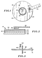
- a rigid magnetic disk 16 ( Figures 1 and 2) constitutes a data recording medium, is rotatable about a vertical axis and has a substantially planar and horizontal upper surface 18.
- a transducing head support arm 20 forms part of a carriage assembly (not shown) and is supported for linear reciprocation radially of the disk 16.
- a magnetic transducing head or slider 22 is supported by arm 20 by means of a head suspension 24, for movement relative to the disk with the arm. Suspension 24 does not support the head 22 rigidly relative to the arm, but allows for gimballing action of the head, i.e. limited vertical travel and limited rotation about pitch and roll axes.
- an opening 26 At the centre of disk 16 is an opening 26 to accommodate a vertical spindle of a disk drive (not shown) used to rotate the disk.
- upper surface 18 is divided into three annular sectors: a radially inward sector 30 used principally for clamping the disk with respect to the spindle, a head contact region or area or band 32, and a data storage region or area 34.
- head 22 Whenever disk 16 is at rest, or rotating but at a speed substantially below its normal operating range, head 22 is in contact with upper surface 18. But when the disk rotates at least near its operating range, an "air bearing" is formed by air flowing between head 22 and upper surface 18 in the direction of disk rotation, which supports the head in parallel spaced apart relation to the recording surface.
- the distance between a planar bottom surface 36 of head 22 and recording surface 18 sometimes referred to as the "flying height" of the head is about 254 (10 microinches) or less.
- the flying height is low, to position head 22 as close as possible to the recording surface 18. The closer the transducing head the more data can be stored on disk 16.
- arm 20 moves to position head 22 selectively over the recording surface.
- head 22 in an arcuate path could be used instead of arm 20 to accomplish substantially the same result.
- the radial position of head 22 is controlled before and after reading and recording operations, as well as during such operations. More particularly, during such operations head 22 while supported on the air bearing is selectively positioned radially across data storage area 34 either to record or to retrieve data at a particular location on the disk. After such operations and during deceleration of disk 16, arm 20 is moved radially inward to position head 22 directly over head contact area 32. Thus, by the time disk 16 has decelerated sufficiently to permit the head to engage the upper surface, head 22 already is aligned with the head contact area. Prior to the next recording or retrieval operation, acceleration of disk 16 from stop occurs with head 22 initially engaged with area 32. Arm 20 is not actuated to remove the head radially from area 32 until the head is supported by an air bearing, i.e. free of the disk.
- data storage area 34 preferably is polished or otherwise finished to a highly smooth, specular finish, having a surface roughness of at most 2.54 nm (0.1 microinch) to permit the desired low flying height for head 22.
- specular finish is that, as compared to the texturized surface, foreign particles are readily observed, which simplifies optical inspection of disk 16. Roughness in this context means the height of the highest peaks above a nominal horizontal plane of the surface.
- head contact area 32 has a roughness of at least 12.7 nm (0.5 microinches).
- the increased surface roughness of the head contact sector in relation to the remainder of upper surface 18 is achieved by a controlled texturizing of the disk during its manufacture.
- Disc 16 ( Figure 2), is formed of a multiplicity of layers including a substrate 38, a recording layer 52 and a protective cover layer 54 over the recording layer.
- Disc 16 is formed first by polishing grinding or otherwise machining an aluminium substrate disk 38 to provide a substantially flat upper surface of the substrate.
- a nickel-phosphorous (Ni-P) alloy is plated onto the upper surface of the aluminium disk, preferably evenly, to provide a substrate layer 40 substantially uniform in thickness, e.g. about 10 microns.
- alloy layer 40 is polished to a roughness of generally less than 2.54 nm (0.1 microinch), for example, by a known silicon carbide grit lapping process. This normally involves a cloth or paper carrying the grit, and can also involve a liquid slurry containing grit in combination with a cloth or paper if desired.
- the substrate surface is substantially planar and has a nominal roughness.
- the preferred stage for the texturizing operation is immediately after polishing and cleaning alloy layer 40.
- Texturizing is accomplished by means of an apparatus ( Figure 3) including a spindle 42 for supporting and rotating disk 16, and a pulsed mode Nd-YAG (yytrium aluminium garnet) laser 44 supported above the disk.
- the laser 44 may be supported in a vertical orientation (as shown) by structure (not shown) of the apparatus, or may be tilted away from the vertical.
- the structure also enables controlled stepwise movement of the laser 44 radially of the disk.
- the laser 44 is directed towards the disk generating a pulsed laser beam 46 selectively focussed on the upper surface 48 of Ni-P layer 40.
- Laser 44 is an ESI model 44 laser trimming system available from ESI, Inc. of Portland, Oregon, United States of America. Laser 44 is fired at a selected frequency into the disk while spindle 42 and disk 16 rotate.
- the apparatus is used to provide a controlled, strictly delineated head contact area 32, comprising less than ten percent of the surface area of the surface 18.
- the area 32 forms an annular band having a width in the radial direction at least as great as the width of the head 22.
- a salient feature of the present invention is the consistent, uniform texture over the entire head contact area.
- two levels of control are involved: a micro level concerned with individual laser marks or spots, and a macro level concerning the pattern or arrangement of multiple laser spots.
- the nature of the individual laser spots is controlled primarily by the intensity or peak energy at which laser 44 is fired, and the duration of each firing, i.e. the pulse width.
- Somewhat secondary added factors include the way in which beam 46 is focussed, and the angle of approach.
- the vertical direction of the beam upon horizontal substrate surface 48 ( Figure 3) i.e. an approach angle of 90 degrees, yields substantially circular spots, while an inclined angle, e.g. 45 degrees, would yield somewhat elliptical or oblong spots.
- the primary control factors include the frequency of repeated firings of laser 44, the speed of disk rotation, and the amount of radial stepping of the laser.
- One preferred texturizing approach is to orient laser 44 vertically ( Figure 3) and to maintain it stationary while rotating disk 16 and firing the laser at a selected frequency, coordinated with the disk rotational velocity to provide a selected distance between consecutive spots. A single rotation of the disk results in a ring of such spots concentric with central opening 26.
- laser 44 is displaced radially by a desired inter-ring pitch, and with its vertical orientation maintained, fired at the predetermined frequency and phase relative to disk rotation.
- the remaining layers 50, 52 and 54 are applied, preferably by vacuum deposition, to complete disk 16.
- Layer 50 of chrome at a thickness of about 100 mm (1,000 angstroms) is sputter deposited onto the upper surface of the nickel-phosphorous alloy 40, to provide an underlayer for the recording layer 52.
- Layer 52 which can be a cobalt nickel alloy, a cobalt chromium alloy or the like, is sputtered onto the chromium layer to a thickness of about 50 to 70 nm (500 to 700 angstroms).
- Protective layer 54 for example carbon, is deposited onto the recording layer 52 at a thickness of about 30 nm (300 angstroms).
- Each of the layers is of substantially uniform thickness and replicates the surface contours of the surface of the layer below it.
- Process parameters primarily controlling size and shape of individual laser spots are the peak energy or intensity, and pulse duration, with the angle of approach and focus also contributing to the size and shape of any discontinuity.
- a typical spot formed by laser 44 when vertically oriented is shown in Figure 4 and represented in profile in Figure 5 as a single laser crater or spot 56.
- Crater 56 is a combination of two departures from a specular surface plane 58 ( Figure 5) which can be considered the nominal plane of substrate surface 48, in this case the upper surface of nickel-phosphorous alloy layer 40.
- the first of these departures is a central depression or pit 60, with the other being a substantially circular rim or ridge 62 surrounding the pit.
- the height h ( Figure 5) of rim 62 above nominal surface plane 58 is preferably in the range of from 12.7 to 20.32 nm (0.5 to 0.8 microinches) although a head contact area 32 in which rim heights h slightly exceed 25.4 nm (1 microinch) can still perform satisfactorily.
- the depth d ( Figure 5) of pit 60 below plane 58 is typically about twice the rim height h , that is 25.4 to 40.64 nm (1 to 1.67 microinches).
- the preferred surface roughness h of head contact area 32 is within a range of from 12.7 to 25.4 nm (0.5 to 1.0 microinches).
- the diameter D of crater 56 which is equivalent to the diameter of rim 62, usually is in the range of 0.1 to 4.0 mils.
- the process parameters mentioned above can be varied to influence dimensions D, d and h .
- the rim height h is considered the most critical, and varies with peak power over a preferred range from about 0.1 kilowatts to about 5 kilowatts.
- the optimum peak power can of course vary with the particular laser employed, as well as the nature of the surface being texturized. However, in connection with nickel-phosphorous layer 40, it has been found advantageous to operate toward the low end of the 0.1 to 5 kilowatt range, just above a point at which melting occurs.
- Depth d of pit 60 while not as critical as the height h of rim 62, nonethless serves a useful purpose, namely the entrapment and collection of media fragments, head fragments or other debris generated due to head/disk contact. Further, in connection with fluorocarbon lubricant coatings with tendencies toward liquid behaviour, the central depressions retain the lubricant coating when the disc is stopped. However, it is believed that as the disk begins spinning, the lubricant tends to travel upwardly out of the depressions and cover the rims, thus reducing dynamic friction in the head contact area.
- Another useful feature of the invention is the rounded nature of the contours forming the pit and rim, with the rounded rims in particular contributing to substantially enhanced friction and wear characteristics over the long term.
- the rounded contours are believed to result from the flow of material due to surface tension forces while the material is cooling and returning to the solid from the liquid state.
- the alloy soon cools and solidifies, but not before material is drawn outwardly away from the spot centre to form the central depression as well as the surrounding rim, apparently due to surface tension.
- the rounded contours are substantially and measurably more resistant to wear from contact with the transducing head.
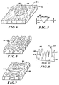
- a desired result is shown in Figure 6 as an enlarged portion of head contact area 32.
- the spacing between adjacent spots in the radial direction (pitch), and the circumferential spacing between adjacent spots, are approximately equal to and can even be less than the average spot diameter of about 1 mil.
- the result is a substantially uniform, continuous texture comprised almost entirely of central depressions and raised rims about the depressions.
- the depressions are preferably distributed to occupy at least one half of the area of the designated treatment region.
- the following are examples within the prescribed texturizing parameter ranges.
- An aluminium rigid disk having a diameter of 203.2 mm (8 inches) and a thickness of 1.905 mm (0.075 inches) was plated with a nickel-phosphorous alloy to a thickness of about 0.01016 mm (400 microinches).
- the laser was operated in the fundamental mode (designated TEM 00 ) and a current of 16.5 milliamperes was applied to the laser, to generate peak power of 0.2. kilowatts.
- the Q switching rate of the laser was maintained at 12 kilohertz, with a pulse duration of about 100 nanoseconds, while the disk was rotated at a rate of 25 rpm.
- the typical and predominant laser spot had a rim or ridge extending from about 12.7 to 20.32 nm (0.5 to 0.8 microinches) above the nominal surface, and a central depression with a depth of about 25.4 to 50.8 nm (1.0 to 2.0 microinches) below the nominal surface plane.
- the average spot diameter was 20.3 ⁇ m (0.8 mils).
- a nickel-phosphorous alloy was plated onto an aluminium disk as in Example 1, and texturized as in Example 1 except that laser 44 was powered by a current of 17.5 milliamperes.
- the resulting spots had rims or ridges from about 25.4 to 50.8 nm (1.0 to 2.0 microinches) above the nominal surface, with depressions of about 101.6 to 127 nm (4.0 to 5.0 microinches) below the nominal surface, with an inter-track pitch of 20.3 ⁇ m (0.8 mils).
- a nickel phosphorous layer was plated onto an aluminium disc and texturized as in Example 1, except that laser 44 was powered by a current of 17.5 milliamperes, and the inter-track pitch was 25.4 ⁇ m (1.0 mil).
- the spot structure was similar to that in Example 2.
- a nickel phosphorous layer was plated onto an aluminium rigid disk and texturized as in Example 1, except that the inter-track pitch was reduced to 12.7 ⁇ m (0.5 mils) and the total width of the area was 3.8 mm (150 mils). Adjacent spots touched one another, with typical spots having ridges raised about 15.24 nm (0.6 microinches) and central depression depths of about 30.48 nm (1.2 microinches).
- the laser beam may be directed onto disc 16 at an inclined angle, e.g. 45 degrees from the horizontal.
- the result is an elongation of each spot into an elliptical or oval shape.
- the beam is tilted yet maintained in a vertical plane containing the disk radius, and when the disk rotational speed and firing frequency are matched to provide a circumferential distance between spots approximating the spot diameter, the result is a circumferential ring of adjacent, elongated spots 64 as on a substrate 66 ( Figure 7).
- control parameters can be varied to provide alternatives to the previously discussed patterns, e.g. by varying the inter-track pitch so that it increases in the radially outward direction, by staggering adjacent rings so that spots in each ring correspond to regions between spots in next adjacent rings, by random arrangement of spots, and by arrangements in which the laser peak power or spot frequency is progressively decreased for radially outward rings in order progressively to decrease roughness in the radially outward direction in the head contact band.
- the laser is used to concentrate energy selectively upon a plurality of locations over a treatment area. This controllably alters the topography of the surface at each location. Adjacent locations are spaced apart from one another by a distance substantially less than the length or width of a magnetic transducing head.
- the roughness of the texturized surface is at least twice the nominal roughness of the specular polished substrate surface.
- Figure 8 shows a substrate 63 with a mechanically textured substrate surface.
- the substrate surface can be textured to a selected roughness to provide a head contact sector dedicated to contact with the transducing head.
- Figure 8 reveals that the surface of substrate 63 has an acicular topography charcteristic of mechanical texturing.
- the textured surface includes peaks 65 and indentations or valleys 67, irregular in height and depth and characterized by steep slopes and pointed edges or ends.
- the pointed edges are areas of stress concentration due to the cutting action of the grit. Consequently, the tips of the highest peaks are susceptible to being broken away when contacted by a transducing head moving relative to the substrate. An upper tip 69 of one of the peaks has been broken away to leave a more planar, though not necessarily horizontal, upper surface 71.
- the multiplicity of generally flat surfaces like surface 71 increases the overall area of surface contact with the transducing head, increasing the stiction and friction problems (commonly referred to as friction build-up).
- the broken away tips tend to adhere to the transducing head as they break away, build up in valleys 67 and expose the magnetic layer in peak regions for possible corrosion sites, or remain free as particulate contaminate, in any case reducing the reliability of the recording system.
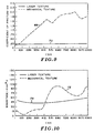
- the charts in Figures 9 and 10 represent comparisons of mechanically textured disks with disks texturized by a laser in accordance with the present invention. More particularly, mechanically textured disks and laser texturized disks were compared both initially and at various stages of contact start-stop testing. All disks were provided with 30 nm (300 angstroms) thick protective layer of sputtered carbon. Actual test results would appear as a series of vertical bars indicating ranges. The lines shown represent a series of midpoints of such vertical bars.
- the self-excited head/gimbal arm vibration energy is defined as the energy spent at the head/disk interface from the time the head overcomes the stiction force to free flying during the start-stop testing. It is measured by integrating the strain experienced by the head arm, measured here by a capacitance probe, over the aforementioned time period. This value, measured as the transducing head takes off from the head contact area when the disk is being accelerated from stop, predicts future wear to the head and head contact region of the disk.
- media texturized in accordance with the present invention is flexible or rigid, a substantial and surprising increase in durability is achieved, measurable principally in its ability to maintain a relatively low coefficient of friction even after numerous contact start-stop cycles, e.g. 10,000 or more. It is believed that the smooth, rounded contours of the surface discontinuities are a major contributing factor to increased durability. A further factor is the improved control of the texturizing process, yielding a high degree of uniformity in surface roughness throughout the specially texturized surface.
- the laser is a preferred device for the controlled texturizing.
- the present invention affords the added advantage of provding a surface area dedicated to contact with the transducing head during accelerations, decelerations and with the disk at rest. Substantially all the remaining disk surface area can have a specular finish ideally suited for reading and recording data.
- the texturizing operation may take place at a different stage of the manufacturing process, for example, after the magnetizable film has been deposited on the substrate surface.
- each deposited layers is of substantially uniform thickness, each replicates the surface contours of the surface on which it is deposited, so that the texturizing can be effected at any stage.
Landscapes
- Engineering & Computer Science (AREA)
- Manufacturing & Machinery (AREA)
- Manufacturing Of Magnetic Record Carriers (AREA)
- Magnetic Record Carriers (AREA)
Claims (28)
- Verfahren zur Herstellung eines magnetischen Aufzeichnungsmediums (16) von der Art, das einen Datenspeicherbereich (34), über den ein Wandlerkopf (22) fliegt, und einen Kopf-Kontaktbereich für den magnetischen Wandlerkopf (22) während der Perioden der Beschleunigung, Abbremsung und des Stillstandes des Aufzeichnungsmediums gegenüber dem Wandlerkopf aufweist, wobei das Verfahren die Ausbildung einer Vielzahl von Schichten (28, 40, 50, 52, 54), von denen zumindest eine ein Substrat (38, 40) aus nichtmagnetisierbarem Material ist, und von denen zumindest eine ein magnetisierbarer Film (52) ist, wobei eine der Schichten eine Außenoberfläche (54) des Mediums bildet, und die Beaufschlagung der Oberfläche einer der Schichten mit einer Strahlungsenergie in einem Behandlungsbereich einschließt, um die Oberfläche der einen Schicht zumindest in deren Behandlungsbereich aufzurauhen, so daß die Außenoberfläche (54) des Aufzeichnungsmediums (16) einen rauhen Oberblächenabschnitt (32) aufgrund der Beaufschlagung der Oberfläche mit der Strahlungsenergie zur Bildung des Kopf-Kontaktbereiches aufweist, während ein anderer Abschnitt (34) der Außenoberfläche des Aufzeichnungsmediums der Datenspeicherbereich ist, der eine glatte Oberfläche aufweist,
dadurch gekennzeichnet, daß die Strahlungsenergie selektiv auf eine Vielzahl von Stellen des Behandlungsbereiches impulsförmig aufgebracht wird, um an jeder dieser Stellen eine Marke zu bilden, die sich von einer Nennoberflächenebene der Schicht, die mit Strahlungsenergie beaufschlagt wird, nach außen bis zu einer Höhe im Bereich von 5,08 bis 50,8 nm (0,2 bis 2 Mikrozoll) erstreckt, einen Durchmesserbereich von 2,54 bis 1,27 µm (0,1 bis 5 Millizoll) aufweist und frei von scharfen Kanten ist. - Verfahren nach Anspruch 1, das weiterhin die folgenden Schritte umfaßt:Ausbilden einer spiegelnden Oberfläche (48) auf dem nichtmagnetisierbaren Substrat (38, 40), wobei diese Substratoberfläche im wesentlichen eben ist und eine Nennrauhigkeit aufweist,Abscheiden des magnetisierbaren Films (52) über der Substratoberfläche (48) mit einer im wesentlichen gleichförmigen Dicke, undwobei die Beaufschlagung der Oberfläche die Konzentration der Strahlungsenergie auf die Vielzahl von Stellen über den Behandlungsbereich auf einer ausgewählten Oberfläche entweder des Substrates (38, 40) oder des Films (52) umfaßt, um in steuerbarer Weise die Topographie der ausgewählten Oberfläche an jeder der Stellen derart zu ändern, daß die Rauhigkeit der ausgewählten Oberfläche über den Behandlungsbereich hinweg zumindestens gleich dem Doppelten der Nennrauhigkeit ist, wobei der Datenspeicherbereich (34) mit der Nennrauhigkeit ausgebildet ist.
- Verfahren nach Anspruch 1 oder 2, bei dem die Beaufschlagung der Oberfläche das Aufbringen von Laserenrgie umfaßt.
- Verfahren nach Anspruch 3, bei dem die impulsförmige Laserenergie an jeder der Stellen eine abgerundete, in der Mitte liegende Vertiefung (60), die sich von einer Nennoberflächenebene der ausgewählten Oberfläche (48) aus nach innen erstreckt, und einen allgemein kreisförmigen und abgerundeten Kranz (62) bildet, der die in der Mitte liegende Vertiefung (60) umgibt und sich von der nominellen Oberflächenebene aus nach außen erstreckt.
- Verfahren nach Anspruch 4, bei dem die Beaufschlagung der Oberfläche die Auswahl der Stellen derart einschließt, daß die Vertiefungen (60) allgemein gleichförmig über den Behandlungsbereich verteilt werden.
- Verfahren nach Anspruch 4 oder 5, bei dem die Konzentration der Energie weiterhin die Ausbildung der Vertiefungen (60) über zumindestens eine Hälfte des Behandlungsbereiches einschließt.
- Verfahren nach einem der Ansprüche 1 bis 6, bei dem der Behandlungsbereich weniger als 10% des Oberflächenbereiches der ausgewählten Oberfläche umfaßt.
- Verfahren nach einem der Ansprüche 4 bis 6 oder in Anspruch 7 unter Rückbeeziehung auf einen der Ansprüche 4 bis 6, bei dem das Substrat (38, 40) eine Platte ist, und bei dem die Beaufschlagung der Oberfläche weiterhin folgende Schritte umfaßt:(a) Drehen der Platte mit einer gesteuerten Drehgeschwindigkeit,(b) gleichzeitiges Aufbringen der impulsförmigen Laserenergie mit einer gesteuerten Frequenz, die der Drehgeschwindigkeit entspricht, um einen ersten Ring zu bilden, der eine Serie von abgerundeten Vertiefungen umfaßt,(c) Verschieben des Lasers in Radialrichtung gegenüber der Platte,(d) Aufbringen der impulsförmigen Laserenergie mit der gesteuerten Frequenz, während die Platte mit der 5 Drehgeschwindigkeit gedreht wird, um einen nachfolgenden Ring zu bilden, der eine nachfolgende Serie von Vertiefungen konzentrisch zum ersten Ring umfaßt und in Radialrichtung von dem ersten Ring durch eine Teilung entfernt ist, die dem Ausmaß der radialen Verschiebung des Lasers entspricht, und(e) Wiederholen der Schritte (c) und (d) zur Ausbildung einer ausgewählten Anzahl von konzentrischen Ringen, wodurch der Behandlungsbereich die ausgewählte Anzahl von konzentrischen Ringen in Form eines ring5 förmigen Bandes umfaßt.
- Verfahren nach Anspruch 8, bei dem bei Ausrichtung der Breite des Wandlerkopfes (22) im wesentlichen in Radialrichtung der Platte (16) das ringförmige Band (22) eine Breite in der Radialrichtung aufweist, die zumindestens so groß wie die Breite des Wandlerkopfes ist.
- Verfahren nach einem der vorhergehenden Ansprüche, bei dem die Konzentration der Energie auf dem Substrat (38, 40) ausgeführt wird.
- Verfahren nach einem der vorhergehenden Ansprüche, bei dem der Substratkörper im wesentlichen starr ist und aus Aluminium gebildet ist, wobei das Verfahren weiterhin die Plattierung einer Schicht (40) aus einer Nickel-Phosphor-Legierung auf das Aluminium in Form einer eine im wesentlichen gleichförmige Dicke aufweisenden Schicht umfaßt, wobei die ausgewählte Oberfläche eine Oberfläche der Nickel-Phosphor-Legierungsschicht ist.
- Verfahren nach einem der vorhergehenden Ansprüche, das weiterhin die Abscheidung einer Schutz-Deckschicht (54) über dem magnetisierbaren Film (52) umfaßt, wobei die Deckschicht eine im wesentlichen gleichförmige Dicke aufweist und die Oberflächenkonturen des magnetisierbaren Filmes (52) nachbildet.
- Verfahren nach einem der vorhergehenden Ansprüche, das weiterhin das Abscheiden einer nichtmagnetisierbaren Unterschicht (50) auf dem Substrat (38, 40) vor der Abscheidung des magnetisierbaren Films (52) über dem Substrat (38, 40) umfaßt, wobei die nichtmagnetisierbare Unterschicht (50) eine im wesentlichen gleichförmige Dicke aufweist und die Oberflächenkonturen des Substrates (38, 40) nachbildet.
- Verfahren nach Anspruch 4 oder 5, bei dem die Konzentration der Energie folgende Schritte einschließt:a) Bewegen des Substrates (38, 40) mit einer gesteuerten Geschwindigkeit in einer Längsrichtung,b) gleichzeitiges Richten eines Strahls (46) der impulsförmigen Laserenergie auf die Oberfläche (48) mit einer gesteuerten Freuquenz zur Bildung einer ersten Reihe der Vertiefungen (60),c) Verschieben des Strahls (46) in Querrichtung mit einer ausgewählten Teilung, und Richten des Strahls (46) aus Laserenergie, während das Substrat (38, 40) in Längsrichtung bewegt wird, um eine nachfolgende Reihe der Vertieffungen (60) parallel zu der ersten Reihe zu bilden, undd) Wiederholen des Schrittes (c) über eine ausgewählte Anzahl von Malen, um den Behandlungsbereich als längsverlaufendes Band mit einer ausgeählten Querbreite zu formen.
- Magnetisches Aufzeichnungsmedium (16) mit einer Vielzahl von Schichten (38, 40, 50, 52, 54), von denen zumindest eine ein Substrat (38, 40) aus nichtmagnetisierbarem Material ist, und von denen zumindest eine ein magnetisierbarer Film (52) ist, wobei eine der Schichten eine Außenoberfläche (54) des Aufzeichnungsmediums (16) ist, die durch auf einen Behandlungsbereich aufgebrachte Strahlungsenergie aufgerauht, ist, um auf der Außenoberfläche (54) einen rauhen Oberflächenabschnitt (32) zu bilden, der einen Kopf-Kontaktbereich für einen magnetischen Wandlerkopf (22) während der Perioden der Beschleunigung, Abbremsung und des Stillstandes des Aufzeichnungsmediums relativ zum Wandlerkopf bildet, während ein anderer Abschnitt (34) der Außenoberfläche des Aufzeichnungsmediums zur Speicherung von Daten dient und eine glatte Oberfläche aufweist, über die im Betrieb der Wandlerkopf (22) fliegt,
dadurch gekennzeichnet, daß die Strahlungsenergie impulsförmig selektiv auf eine Vielzahl von Stellen über den Behandlungsbereich einer der Schichten hinweg aufgebracht wird, wobei an jeder der Stellen eine Marke gebildet wird, die von einer nominellen Oberflächenebene der Schicht, die mit der Strahlungsenergie beaufschlagt wird, nach außen hin über eine Höhe im Bereich von 5,.08 bis 50,8 nm (0,2 bis 2 Mikrozoll) erstreckt, einen Durchmesser im Bereich von 2,54 bis 127 µm (0,1 bis 5 Millizoll) aufweist und abgerundet und frei von scharfen Kanten ist. - Bauteil nach Anspruch 15, bei dem der rauhe Oberflächenabschnitt (32) eine Rauhigkeit aufweist, die zumindest doppelt so groß ist, wie die nominelle Rauhigkeit des Datenspeicherabschnittes (34).
- Bauteil nach Anspruch 15 oder 16, bei dem der rauhe Oberflächenabschnitt (32) eine Rauhigkeit von zumindest 12,7 nm (0,5 Mikrozoll) aufweist, während der Datenspeicherabschnitt (34) eine Rauhigkeit von höchstens 2,54 nm (0,1 Mikrozoll) aufweist.
- Bauteil nach Anspruch 15, bei dem das Bauteil eine Platte (16) ist und das nichtmagnetisierbare Substrat ein im wesentlichen starres Substrat (38) mit einer im wesentlichen ebenen Oberfläche umfaßt, und
wobei jede der Marken Vertiefungen (60), die sich von der nominellen Oberflächenebene aus nach innen in Richtung auf das Substrat (38) über eine Strecke im Bereich von 127 bis 254 nm (0,5 bis 10 Mikrozoll) erstrecken, und einen abgerundeten Kranz (62) einschließt, der jede Vertiefung (60) im wesentlichen umgibt und sich von der Nennoberflächenebene über eine Höhe von 5,08 nm bis 50,8 nm (0,2 bis 2 Mikrozoll) nach außen erstreckt, wobei jeder der Kränze (62) einen Durchmesser im Bereich von 2,54 bis 1,27 µm (0,1 bis 5 Millizoll) aufweist. - Bauteil nach Anspruch 18, bei dem der rauhe Oberflächenabschnitt (32) ein ringförmiges Band im wesentlichen konzentrisch zu einer Drehachse der Platte (16) ist und eine radiale Abmessung aufweist, die die Breite des Wandlerkopfes (22) übersteigt.
- Bauteil nach Anspruch 18 oder 19, bei dem die Vertiefungen (60) und die entsprechenden Kränze (62) zumindest 50% des Oberflächenbereiches des rauhen Oberflächenabschnittes (32) umfassen.
- Bauteil nach einem der Ansprüche 15 bis 20, bei dem benachbarte Vertiefungen in dem rauhen Oberflächenabschnitt (32) einen Abstand voneinander aufweisen, der nicht größer als 127 µm (5 Millizoll) ist.
- Bauteil nach Anspruch 15, bei dem das Bauteil eine Platte (16) ist, bei dem die Außenoberfläche eine Nennoberflächenebene aufweist und das nichtmagnetisierbare Substrat ein im wesentlichen starres Substrat (38) mit einer im wesentlichen ebenen Oberfläche umfaßt, und
wobei der Datenspeicherbereich der Substratoberfläche (48) einen ringförmigen ersten Datenbereich (34) mit einer Oberflächenrauhigkeit von höchstens 5,08 nm (0,2 Mikrozoll) aufweist und der rauhe Oberflächenabschnitt (32) einen angrenzenden ringförmigen zweiten Bereich (32) umfaßt, wobei die Substratoberfläche eine Nennoberflächenebene aufweist und über den gesamten zweiten Bereich (32) hinweg eine Vielzahl von Vertiefungen (60), die sich von der Nennebene über zumindest 6,3 nm (0,25 Mikrozoll) nach innen erstrecken, und Wülsten (62) benachbart zu den Vertiefungen (60) einschließt, die sich von der Nennebene aus über eine Höhe von zumindest 10,16 nm (0,4 Mikrozoll) nach außen hin erstrecken, wobei die Kränze (62) abgerundet und frei von scharfen Kanten sind. - Bauteil nach Anspruch 22, bei dem der zweite Bereich (32) radial einwärts von dem ersten Bereich (34) liegt.
- Bauteil nach Anspruch 22 oder 23, bei dem der zweite Bereich (34) in Radialrichtung der Platte (16) eine Breite im Bereich von 1,27 bis 12,7 nm (0,05 bis 0,5 Mikrozoll) aufweist.
- Bauteil nach einem der Ansprüche 22 bis 24, bei dem die Vertiefungen (60) und Kränze (62) allgemein kreisförmig sind, wobei benachbarte Vertiefungen (60) eine Abstand voneinander von höchstens 1,27 µm (5 Millizoll) aufweisen.
- Bauteil nach einem der Ansprüche 22 bis 25, bei dem die Kränze (62) Durchmesser im Bereich von 2,54 bis 127 µm (0,1 bis 5,0 Millizoll) aufweisen.
- Bauteil nach einem der Ansprüche 15 bis 26, bei dem das Substrat (38, 40) einen Aluminiumkörper (38) und eine Schicht (40) aus einer Nickel-Phosphor-Legierung einschließt, die auf dem Körper aufplattiert ist, wobei die Marken (60) in der Nickel-Phosphor-Legierung ausgebildet sind, und wobei der magnetisierbare Film (52) über der Legierung gebildet ist und die Oberflächenkonturen der Substratoberfläche nachbildet.
- Bauteil nach Anspruch 27, das weiterhin eine Schutzschicht (54) einschließt, die auf dem magnetisierbaren Film (52) als Schicht mit im wesentlichen gleichförmiger Dicke abgeschieden ist, so daß sie die Oberflächenkonturen des magnetisierbaren Films nachbildet.
Applications Claiming Priority (2)
| Application Number | Priority Date | Filing Date | Title |
|---|---|---|---|
| US491586 | 1990-03-12 | ||
| US07/491,586 US5062021A (en) | 1990-03-12 | 1990-03-12 | Selectively textured magnetic recording media |
Publications (2)
| Publication Number | Publication Date |
|---|---|
| EP0447025A1 EP0447025A1 (de) | 1991-09-18 |
| EP0447025B1 true EP0447025B1 (de) | 1996-11-06 |
Family
ID=23952845
Family Applications (1)
| Application Number | Title | Priority Date | Filing Date |
|---|---|---|---|
| EP91300614A Expired - Lifetime EP0447025B1 (de) | 1990-03-12 | 1991-01-28 | Magnetischer Aufzeichnungsträger und Verfahren zu seiner Herstellung |
Country Status (5)
| Country | Link |
|---|---|
| US (1) | US5062021A (de) |
| EP (1) | EP0447025B1 (de) |
| JP (1) | JPH03272018A (de) |
| DE (1) | DE69122980T2 (de) |
| SG (1) | SG49693A1 (de) |
Families Citing this family (133)
| Publication number | Priority date | Publication date | Assignee | Title |
|---|---|---|---|---|
| JPH04195717A (ja) * | 1990-11-26 | 1992-07-15 | Hitachi Ltd | 磁気記録媒体、その製造方法及び磁気記録装置 |
| WO1993012520A1 (en) * | 1991-12-17 | 1993-06-24 | Certus Magnetics | Magnetic disk medium with designed textured surfaces and controlled surface roughness and method of providing same |
| US5768075A (en) * | 1991-12-17 | 1998-06-16 | Baradun R&D Ltd. | Disk medium w/magnetically filled features aligned in rows and columns |
| WO1993021629A1 (en) * | 1992-04-15 | 1993-10-28 | Tulip Memory Systems, Inc. | Precision-etched textured stop/start zone for magnetic-recording disks |
| US5589247A (en) * | 1992-12-22 | 1996-12-31 | Minnesota Mining And Manufacturing Company | Magnetic recording medium having an embossed backcoat layer |
| US5482497A (en) * | 1992-12-30 | 1996-01-09 | International Business Machines Corporation | Method and apparatus for texturing zones of a magnetic disk |
| TW300879B (de) * | 1993-11-10 | 1997-03-21 | Ibm | |
| US5768076A (en) * | 1993-11-10 | 1998-06-16 | International Business Machines Corporation | Magnetic recording disk having a laser-textured surface |
| US5993937A (en) * | 1993-11-30 | 1999-11-30 | Matsushita Electric Industrial Co., Ltd. | Magneto-optic recording medium and method of fabricating the same |
| US5939170A (en) * | 1993-12-28 | 1999-08-17 | Hoya Corporation | Magnetic recording medium |
| DE19524220A1 (de) * | 1994-07-04 | 1996-01-11 | Mitsubishi Chem Corp | Magnetisches Aufzeichnungsmedium, Verfahren zu dessen Herstellung, und Aufnahme- und Wiedergabeverfahren |
| US5800931A (en) * | 1994-09-29 | 1998-09-01 | Carnegie Mellon University | Magnetic recording medium with a MgO sputter deposited seed layer |
| US6649277B1 (en) | 1994-09-29 | 2003-11-18 | Carnegie Mellon University | Structure for and method of making magnetic recording media |
| US6146740A (en) * | 1994-11-28 | 2000-11-14 | Matsushita Electric Industrial Co., Ltd. | Magnetic recording medium and method of fabricating the same |
| US5981902A (en) * | 1994-12-15 | 1999-11-09 | Mitsubishi Chemical Corporation | Texturing apparatus for magnetic recording medium and magnetic recording medium process thereby |
| US5528922A (en) * | 1994-12-27 | 1996-06-25 | International Business Machines Corporation | Method of making disk bumps with laser pulses for calibrating PZT sliders |
| US5586040A (en) * | 1995-01-27 | 1996-12-17 | International Business Machines Corporation | Process and apparatus for controlled laser texturing of magnetic recording disk |
| US5539213A (en) * | 1995-01-27 | 1996-07-23 | International Business Machines Corporation | Process and apparatus for laser analysis of surface having a repetitive texture pattern |
| US5550696A (en) * | 1995-01-27 | 1996-08-27 | International Business Machines Corporation | Magnetic recording disk having textured test band for controlling texture in the slider landing zone |
| US5582878A (en) * | 1995-03-24 | 1996-12-10 | Showa Denko Kabushiki Kaisha | Process for producing magnetic recording medium |
| US5506017A (en) * | 1995-06-07 | 1996-04-09 | Komag Incorporated | Method for texturing magnetic media |
| US5798164A (en) | 1995-06-23 | 1998-08-25 | Stormedia, Inc. | Zone textured magnetic recording media |
| US6075677A (en) * | 1995-07-27 | 2000-06-13 | Seagate Technology, Inc. | Method for positioning a read/write head to reduce wear for proximity recording in a magnetic disk storage system |
| EP0853528A4 (de) * | 1995-08-22 | 2002-01-30 | Seagate Technology Llc | Oberflächenbehandlung mittels laserbestrahlung von aufnahmeträgern |
| US6048255A (en) * | 1995-08-22 | 2000-04-11 | Seagate Technology, Inc. | Pulsed laser surface treatments for magnetic recording media |
| US5723033A (en) * | 1995-09-06 | 1998-03-03 | Akashic Memories Corporation | Discrete track media produced by underlayer laser ablation |
| US6043961A (en) * | 1995-09-08 | 2000-03-28 | Kao Corporation | Magnetic recording medium and method for producing the same |
| US5759419A (en) * | 1995-10-05 | 1998-06-02 | Mitsubishi Chemical Corporation | Method of manufacturing a magnetic recording medium and a semiconductor laser texturing apparatus |
| US5976714A (en) * | 1995-10-23 | 1999-11-02 | Mitsubishi Chemical Corporation | Magnetic recording medium and method of producing the same |
| US6057984A (en) * | 1995-10-25 | 2000-05-02 | Mitsubishi Chemical Corporation | Method for data writing/read-out using a contact start and stop system |
| US6287663B1 (en) | 1995-10-31 | 2001-09-11 | Kabushiki Kaisha Ohara | Glass-ceramic substrate for a magnetic information storage medium |
| US5595768A (en) * | 1995-11-02 | 1997-01-21 | Komag, Incorporated | Laser disk texturing apparatus |
| JPH09138941A (ja) * | 1995-11-13 | 1997-05-27 | Nec Corp | 磁気ディスク基板およびその製造方法 |
| US5798884A (en) | 1995-12-13 | 1998-08-25 | International Business Machines Corporation | Multiple zone data storage system and method |
| US5729399A (en) * | 1995-12-13 | 1998-03-17 | International Business Machines Corporation | Contact start/stop disk drive with minimized head-disk wear in textured landing zone |
| JPH09167337A (ja) * | 1995-12-15 | 1997-06-24 | Nec Corp | 磁気ディスクおよびその製造方法 |
| US6239935B1 (en) * | 1996-02-05 | 2001-05-29 | Seagate Technolgy Llc | Method and apparatus for starting a hard disk drive having separate landing and data zones |
| US5718811A (en) * | 1996-02-28 | 1998-02-17 | Seagate Technology, Inc. | Sputter textured magnetic recording medium |
| JPH09237419A (ja) * | 1996-02-29 | 1997-09-09 | Showa Denko Kk | 磁気記録媒体の製造方法 |
| US5658475A (en) * | 1996-03-11 | 1997-08-19 | International Business Machines Corporation | Apparatus for laser texturing disks |
| EP0897576B1 (de) * | 1996-05-09 | 2000-03-15 | Seagate Technology, Inc. | Laserstrukturierung eines magnetischen aufzeichnungsmediums unter verwendung einer mehrfachlinsenfokussierung |
| US5783797A (en) * | 1996-05-09 | 1998-07-21 | Seagate Technology, Inc. | Laser texturing of magnetic recording medium using a crystal material |
| EP0962916A1 (de) * | 1996-05-09 | 1999-12-08 | Seagate Technology, Inc. | Laserstrukturierung eines magnetischen Aufzeichnungsmediums unter Verwendung einer Mehrfachlinsenfokussierung |
| WO1997042629A1 (en) * | 1996-05-09 | 1997-11-13 | Seagate Technology, Inc. | Magnetic recording medium with laser textured glass or glass-ceramic substrate |
| JPH11509483A (ja) * | 1996-05-13 | 1999-08-24 | シーゲート テクノロジー,インコーポレイテッド | 磁気媒体の成形ビームレーザによるテクスチャ付け加工 |
| US5895712A (en) * | 1996-05-21 | 1999-04-20 | Seagate Technology, Inc. | Magnetic recording medium with improved coercivity |
| US5948288A (en) * | 1996-05-28 | 1999-09-07 | Komag, Incorporated | Laser disk texturing apparatus |
| DE69635850T2 (de) | 1996-05-28 | 2006-10-05 | Kabushiki Kaisha Ohara, Sagamihara | Glaskeramisches Trägermaterial für magnetisches Informationsaufzeichnungsmedium und Verfahren zu seiner Herstellung |
| US5980997A (en) * | 1996-06-03 | 1999-11-09 | Komag, Incorporated | Method for preparing a substrate for a magnetic disk |
| US6103404A (en) * | 1996-06-03 | 2000-08-15 | Komag, Inc. | Laser textured magnetic disk comprising NiNb |
| US6020045A (en) * | 1996-06-05 | 2000-02-01 | Seagate Technology, Inc. | Textured magnetic recording medium having a transition zone |
| JPH1097715A (ja) * | 1996-07-31 | 1998-04-14 | Asahi Komagu Kk | 磁気記録媒体用基板および磁気記録媒体 |
| JP3930113B2 (ja) * | 1996-08-30 | 2007-06-13 | Hoya株式会社 | 磁気ディスク用ガラス基板 |
| US6059555A (en) * | 1996-09-04 | 2000-05-09 | International Business Machines Corporation | Optical apparatus for dual-beam laser texturing |
| US5830514A (en) * | 1996-09-04 | 1998-11-03 | International Business Machines Corporation | Controlling pulses in a laser texturing tool |
| US5790433A (en) * | 1996-09-05 | 1998-08-04 | International Business Machines Corporation | Method for controlling laser power in a texturing process |
| US6350506B2 (en) * | 1996-09-17 | 2002-02-26 | Corning Incorporated | Textured surface and method |
| US5699160A (en) * | 1996-09-23 | 1997-12-16 | International Business Machines Corporation | Optical apparatus for inspecting laser texture |
| US5926266A (en) * | 1996-09-23 | 1999-07-20 | International Business Machines Corporation | Optical apparatus for rapid defect analysis |
| MY119299A (en) * | 1996-10-04 | 2005-04-30 | Showa Denko Kk | Magnetic recording medium and process for producing same |
| US5822211A (en) * | 1996-11-13 | 1998-10-13 | International Business Machines Corporation | Laser texturing apparatus with dual laser paths having an independently adjusted parameter |
| US6132843A (en) * | 1996-11-14 | 2000-10-17 | Nippon Sheet Glass Do., Ltd. | Glass substrate for magnetic disks |
| US5828491A (en) * | 1996-12-20 | 1998-10-27 | The Regents Of The University Of California | Phase plate technology for laser marking of magnetic discs |
| US6021032A (en) | 1997-01-15 | 2000-02-01 | Seagate Technology, Inc. | Magnetic recording medium with laser textured data zone |
| US5952058A (en) | 1997-01-15 | 1999-09-14 | Seagate Technology, Inc. | Laser texturing magnetic recording medium using fiber optics |
| US5965215A (en) * | 1997-01-15 | 1999-10-12 | Seagate Technology, Inc. | Method for laser texturing a landing zone and a data zone of a magnetic recording medium |
| US6207926B1 (en) | 1997-01-15 | 2001-03-27 | Seagate Technology Llc | Fiber optic laser texturing with optical probe feedback control |
| KR100466290B1 (ko) | 1997-01-15 | 2005-01-13 | 시게이트 테크놀로지 엘엘씨 | 자기 기록 매체 |
| US5907144A (en) * | 1997-02-05 | 1999-05-25 | International Business Machines Corporation | Microscopic bar code for component identification and method for making same |
| US5910262A (en) * | 1997-02-06 | 1999-06-08 | International Business Machines Corporation | Method and tool for laser texturing of glass substrates |
| US6151338A (en) * | 1997-02-19 | 2000-11-21 | Sdl, Inc. | High power laser optical amplifier system |
| US5912791A (en) * | 1997-03-14 | 1999-06-15 | Seagate Technology, Inc. | Landing zone design for a magnetic disc |
| US5951891A (en) * | 1997-03-24 | 1999-09-14 | International Business Machines Corporation | Optical apparatus for monitoring profiles of textured spots during a disk texturing process |
| US5981903A (en) * | 1997-03-28 | 1999-11-09 | International Business Machines Corporation | Laser system for simultaneous texturing of two sides of a substrate |
| US5963569A (en) * | 1997-03-28 | 1999-10-05 | International Business Machines Corporation | Multiple channel acousto-optic modulators |
| US6117499A (en) * | 1997-04-09 | 2000-09-12 | Komag, Inc. | Micro-texture media made by polishing of a selectively irradiated surface |
| JPH117622A (ja) * | 1997-04-25 | 1999-01-12 | Hitachi Ltd | 磁気記録媒体用基板、磁気記録媒体及び磁気記録媒体の製造方法 |
| JPH10320847A (ja) * | 1997-05-20 | 1998-12-04 | Sony Corp | ディスク基板及びその製造方法並びにその製造装置 |
| US6205002B1 (en) | 1997-06-13 | 2001-03-20 | International Business Machines Corporation | Disk drive with textured slider contact region |
| US5853820A (en) * | 1997-06-23 | 1998-12-29 | Seagate Technology, Inc. | Controlled laser texturing glass-ceramic substrates for magnetic recording media |
| JPH1128591A (ja) * | 1997-07-07 | 1999-02-02 | Hitachi Electron Eng Co Ltd | テクスチャ加工装置 |
| US6195234B1 (en) | 1997-07-21 | 2001-02-27 | Seagate Technology, Inc. | Magnetic discs with raised features in the clamping area |
| WO1999009549A1 (en) * | 1997-08-15 | 1999-02-25 | Seagate Technology, Inc. | Textured work-hardened magnetic media and their fabrication |
| US6200441B1 (en) | 1997-08-27 | 2001-03-13 | Western Digital Corporation | Multiple station vacuum deposition apparatus for texturing a substrate using a scanning beam |
| US6068728A (en) * | 1997-08-28 | 2000-05-30 | Seagate Technology, Inc. | Laser texturing with reverse lens focusing system |
| US5837330A (en) * | 1997-08-28 | 1998-11-17 | Seagate Technology, Inc. | Dual fiber optic laser texturing |
| US5956217A (en) * | 1997-08-28 | 1999-09-21 | Seagate Technology, Inc. | Reference disk for determining glide height |
| US5910235A (en) * | 1997-09-12 | 1999-06-08 | Western Digital Corporation | Etching and pipelined texturing of a substrate in a stationary vacuum deposition machine |
| US5877858A (en) * | 1997-09-19 | 1999-03-02 | International Business Machines Corporation | Textured surface monitoring and control apparatus |
| US5861196A (en) * | 1997-09-25 | 1999-01-19 | Seagate Technology, Inc. | Laser texturing a glass or glass-ceramic substrate |
| US5945197A (en) * | 1997-10-27 | 1999-08-31 | Seagate Technology | Laser texturing of magnetic recording medium using multiple lens focusing |
| JP3300266B2 (ja) * | 1997-11-06 | 2002-07-08 | 株式会社日立製作所 | 磁気ディスク装置 |
| US6108169A (en) * | 1997-12-03 | 2000-08-22 | Quantum Corporation | Randomly laser-textured magnetic recording media |
| US6663938B1 (en) | 1997-12-12 | 2003-12-16 | Seagate Technology Llc | Media contact zone with bell-shaped texturing features |
| US6535352B2 (en) | 1997-12-15 | 2003-03-18 | Seagate Technology Llc | Head media interface for stiction control |
| WO1999040575A1 (en) * | 1998-02-10 | 1999-08-12 | Seagate Technology Llc | Magnetic recording medium with patterned substrate |
| US6275029B1 (en) * | 1998-02-10 | 2001-08-14 | Seagate Technology Llc | System and method for monitoring flying height using textured disks |
| US6764738B1 (en) | 1998-02-10 | 2004-07-20 | Seagate Technology Llc | Magnetic recording medium with patterned substrate |
| US6519114B1 (en) * | 1998-03-19 | 2003-02-11 | Seagate Technology, Inc. | Magnetic storage medium having a textured zone |
| US5978091A (en) * | 1998-06-26 | 1999-11-02 | Hmt Technology Corporation | Laser-bump sensor method and apparatus |
| US6259575B1 (en) | 1998-07-01 | 2001-07-10 | Iomega Corporation | Readable indelible mark on storage media |
| US6324026B1 (en) | 1998-07-01 | 2001-11-27 | Iomega Corporation | Readable indelible mark on storage media |
| JP2000067430A (ja) * | 1998-08-19 | 2000-03-03 | Fujitsu Ltd | 磁気ディスク装置 |
| US6299947B1 (en) | 1999-01-20 | 2001-10-09 | Komag, Inc. | Method of forming a magnetic hard disk with elliptical shaped laser bumps |
| US6611400B1 (en) | 1999-01-22 | 2003-08-26 | Seagate Technology Llc | Texture structure for optimizing head disc interface |
| US6143375A (en) * | 1999-01-28 | 2000-11-07 | Komag, Incorporated | Method for preparing a substrate for a magnetic disk |
| US6403919B1 (en) | 1999-03-01 | 2002-06-11 | Komag, Incorporated | Disk marking system |
| US6093472A (en) * | 1999-06-23 | 2000-07-25 | Seagate Technology, Inc. | Magnetic recording medium with laser textured glass or glass-ceramic substrate |
| US6468596B1 (en) | 1999-07-15 | 2002-10-22 | Seagate Technology Llc | Laser-assisted in-situ fractionated lubricant and a new process for surface of magnetic recording media |
| US6388229B1 (en) | 1999-08-13 | 2002-05-14 | International Business Machines Corporation | Method for laser texturing magnetic recording disk |
| US6536265B1 (en) | 1999-12-02 | 2003-03-25 | Seagate Technology Llc | Micro-textured glide sliders for super-smooth media |
| US6432563B1 (en) | 2000-04-03 | 2002-08-13 | Carnegie Mellon University | Zinc enhanced hard disk media |
| US6342707B1 (en) | 2000-06-20 | 2002-01-29 | Katsina Optics, Inc. | Laser scatterometer with adjustable beam block |
| US6596417B1 (en) | 2000-09-29 | 2003-07-22 | Carnegie Mellon University | Magnetic recording medium with a Ga3Pt5 structured underlayer and a cobalt-based magnetic layer |
| US6674612B2 (en) | 2000-11-02 | 2004-01-06 | Seagate Technology Llc | Magnetic transducing slider with leading edge crossbar |
| US6785079B2 (en) * | 2001-03-16 | 2004-08-31 | Hitachi Global Storage Technologies Netherlands B.V. | Method and apparatus for estimating the flyheight of an airbearing slider in a storage device |
| US6846576B1 (en) | 2002-04-10 | 2005-01-25 | Seagate Technology Llc | Coupling enhancement for medium with anti-ferromagnetic coupling |
| US6995934B2 (en) * | 2002-12-23 | 2006-02-07 | Imation Corp. | Noise suppressed data storage media |
| SG109001A1 (en) * | 2003-07-10 | 2005-02-28 | Shinetsu Chemical Co | Substrate for magnetic recording medium |
| US20050195510A1 (en) * | 2004-03-04 | 2005-09-08 | Quantum Corporation | Feedback-controlled optical servo writer |
| US7301726B1 (en) * | 2004-11-04 | 2007-11-27 | Komag, Inc. | Banded LZT CSS zone |
| WO2007044798A2 (en) * | 2005-10-11 | 2007-04-19 | Gsi Group Corporation | Optical metrological scale and laser-based manufacturing method therefor |
| US20070131860A1 (en) * | 2005-12-12 | 2007-06-14 | Freeouf John L | Quadrupole mass spectrometry chemical sensor technology |
| US8298611B2 (en) * | 2008-07-23 | 2012-10-30 | Seagate Technology Llc | Discrete track media |
| US7964013B2 (en) * | 2009-06-18 | 2011-06-21 | University Of Louisiana At Lafayette | FeRh-FePt core shell nanostructure for ultra-high density storage media |
| US10392718B2 (en) * | 2009-09-04 | 2019-08-27 | Apple Inc. | Anodization and polish surface treatment |
| US8611044B2 (en) | 2011-06-02 | 2013-12-17 | International Business Machines Corporation | Magnetic head having separate protection for read transducers and write transducers |
| US9644283B2 (en) | 2011-09-30 | 2017-05-09 | Apple Inc. | Laser texturizing and anodization surface treatment |
| DE102011121545B4 (de) * | 2011-12-20 | 2013-07-11 | Eads Deutschland Gmbh | Verfahren zur Strukturierung und chemischen Modifikation einer Oberfläche eines Werkstücks |
| US8837082B2 (en) | 2012-04-27 | 2014-09-16 | International Business Machines Corporation | Magnetic recording head having quilted-type coating |
| US9036297B2 (en) | 2012-08-31 | 2015-05-19 | International Business Machines Corporation | Magnetic recording head having protected reader sensors and near zero recession writer poles |
| US8780496B2 (en) | 2012-09-21 | 2014-07-15 | International Business Machines Corporation | Device such as magnetic head having hardened dielectric portions |
| US10478311B2 (en) | 2017-08-14 | 2019-11-19 | Globus Medical, Inc. | Medical devices including titanium surface treatment |
Citations (6)
| Publication number | Priority date | Publication date | Assignee | Title |
|---|---|---|---|---|
| JPS5423508A (en) * | 1977-07-25 | 1979-02-22 | Nippon Telegr & Teleph Corp <Ntt> | Magnetic disc medium |
| US4377288A (en) * | 1981-04-13 | 1983-03-22 | Sulprizio Michael S | Tennis racket |
| JPS63275029A (ja) * | 1987-05-01 | 1988-11-11 | Tdk Corp | 磁気ディスク並びにその加工方法及び加工装置 |
| JPH01229419A (ja) * | 1988-03-08 | 1989-09-13 | Fuji Photo Film Co Ltd | 磁気記録媒体 |
| EP0344759A2 (de) * | 1988-06-03 | 1989-12-06 | Insite Peripherals, Inc. | Medium mit hoher Spurdichte und optischen Servospuren; Methode und Gerät zum Einschreiben der Spuren auf das Medium |
| US4996662A (en) * | 1983-10-03 | 1991-02-26 | Wang Laboratories, Inc. | Method for generating document using tables storing pointers and indexes |
Family Cites Families (10)
| Publication number | Priority date | Publication date | Assignee | Title |
|---|---|---|---|---|
| JPS5584045A (en) * | 1978-12-19 | 1980-06-24 | Nec Corp | Magnetic memory substance and its manufacture |
| US4522848A (en) * | 1983-04-28 | 1985-06-11 | Patel Pravin K | Process of preparing a recording member having a variable thickness recording layer |
| US4626941A (en) * | 1983-05-26 | 1986-12-02 | Fujitsu Limited | Method and apparatus for suppressing the evaporation of lubricant film coated on magnetic disks of a disk storage |
| US4609964A (en) * | 1983-10-11 | 1986-09-02 | Coronet Paper Corporation | Reinforcement for magnetic recording disk |
| JPS61115238A (ja) * | 1984-11-09 | 1986-06-02 | Fuji Photo Film Co Ltd | フレキシブル磁気デイスクとその製造方法 |
| US4698251A (en) * | 1985-01-22 | 1987-10-06 | Victor Company Of Japan, Limited | Magnetic recording medium and method of producing the same |
| JPS62256214A (ja) * | 1986-04-28 | 1987-11-07 | Hoya Corp | 磁気記録媒体 |
| DE3629582A1 (de) * | 1986-08-30 | 1988-03-03 | Basf Ag | Verfahren zur oberflaechenbearbeitung scheibenfoermiger vernickelter aluminiumsubstrate |
| JPH01317226A (ja) * | 1988-06-16 | 1989-12-21 | Mitsubishi Electric Corp | 磁気ディスク用基板 |
| JP2545444B2 (ja) * | 1988-06-17 | 1996-10-16 | 共同印刷株式会社 | 磁気記録媒体及びその製造方法 |
-
1990
- 1990-03-12 US US07/491,586 patent/US5062021A/en not_active Expired - Lifetime
- 1990-11-30 JP JP2336997A patent/JPH03272018A/ja active Pending
-
1991
- 1991-01-28 DE DE69122980T patent/DE69122980T2/de not_active Expired - Fee Related
- 1991-01-28 EP EP91300614A patent/EP0447025B1/de not_active Expired - Lifetime
- 1991-01-28 SG SG1996004123A patent/SG49693A1/en unknown
Patent Citations (6)
| Publication number | Priority date | Publication date | Assignee | Title |
|---|---|---|---|---|
| JPS5423508A (en) * | 1977-07-25 | 1979-02-22 | Nippon Telegr & Teleph Corp <Ntt> | Magnetic disc medium |
| US4377288A (en) * | 1981-04-13 | 1983-03-22 | Sulprizio Michael S | Tennis racket |
| US4996662A (en) * | 1983-10-03 | 1991-02-26 | Wang Laboratories, Inc. | Method for generating document using tables storing pointers and indexes |
| JPS63275029A (ja) * | 1987-05-01 | 1988-11-11 | Tdk Corp | 磁気ディスク並びにその加工方法及び加工装置 |
| JPH01229419A (ja) * | 1988-03-08 | 1989-09-13 | Fuji Photo Film Co Ltd | 磁気記録媒体 |
| EP0344759A2 (de) * | 1988-06-03 | 1989-12-06 | Insite Peripherals, Inc. | Medium mit hoher Spurdichte und optischen Servospuren; Methode und Gerät zum Einschreiben der Spuren auf das Medium |
Non-Patent Citations (1)
| Title |
|---|
| PATENT ABSTRACTS OF JAPAN, unexamined applications, P ffield, vol.12 , No. 243, July 9, 1988 THE PATENT OFFICE JAPANESE GOVERNMENT page 91 P 728 * |
Also Published As
| Publication number | Publication date |
|---|---|
| DE69122980T2 (de) | 1997-03-06 |
| US5062021A (en) | 1991-10-29 |
| SG49693A1 (en) | 1998-06-15 |
| EP0447025A1 (de) | 1991-09-18 |
| DE69122980D1 (de) | 1996-12-12 |
| JPH03272018A (ja) | 1991-12-03 |
Similar Documents
| Publication | Publication Date | Title |
|---|---|---|
| EP0447025B1 (de) | Magnetischer Aufzeichnungsträger und Verfahren zu seiner Herstellung | |
| US5108781A (en) | Process for manufacturing selectively textured magnetic recording media | |
| US6229670B1 (en) | Laser texturing of a magnetic disk media to create a contact zone of ridge sections spaced a greater radial distance apart than the width of the ridge section | |
| US6048255A (en) | Pulsed laser surface treatments for magnetic recording media | |
| WO1997043079A1 (en) | Shaped-beam laser texturing of magnetic media | |
| US6404590B1 (en) | Magnetic media with randomly positioned texturing features | |
| US6187413B1 (en) | Media landing zone with recess for texturing features | |
| US5834731A (en) | Laser texturing apparatus with bernoulli holder | |
| US6381098B1 (en) | Laser textured transducing head slider | |
| EP0956556B1 (de) | Magnetische aufzeichnungsträger mit zufällig verteilten lasertexturen | |
| JP3199266B2 (ja) | 磁気記録媒体のレーザ表面処理 | |
| US6205002B1 (en) | Disk drive with textured slider contact region | |
| US20010008715A1 (en) | Continuous texture features for a disk substrate | |
| EP0897576B1 (de) | Laserstrukturierung eines magnetischen aufzeichnungsmediums unter verwendung einer mehrfachlinsenfokussierung | |
| US6320728B1 (en) | Laser textured magnetic surface micro-ridges/grooves to enhance magnetic recording performance | |
| US5945197A (en) | Laser texturing of magnetic recording medium using multiple lens focusing | |
| JP4019561B2 (ja) | 磁気記録媒体の評価手法および設計方法 | |
| US6663938B1 (en) | Media contact zone with bell-shaped texturing features | |
| EP0962916A1 (de) | Laserstrukturierung eines magnetischen Aufzeichnungsmediums unter Verwendung einer Mehrfachlinsenfokussierung | |
| KR20000010874A (ko) | 복수 렌즈 포커싱 시스템을 이용한 텍스춰링된 표면을 갖는자기 기록 매체 및 그 제조 방법 | |
| JPH1011873A (ja) | 磁気ディスク、その記録再生方法及び記録再生装置 | |
| GB2357183A (en) | Low resonance texturing of magnetic media | |
| JPH10177717A (ja) | 磁気ディスク及び磁気ディスク装置 |
Legal Events
| Date | Code | Title | Description |
|---|---|---|---|
| PUAI | Public reference made under article 153(3) epc to a published international application that has entered the european phase |
Free format text: ORIGINAL CODE: 0009012 |
|
| AK | Designated contracting states |
Kind code of ref document: A1 Designated state(s): DE FR GB IT NL |
|
| 17P | Request for examination filed |
Effective date: 19920115 |
|
| 17Q | First examination report despatched |
Effective date: 19940715 |
|
| GRAG | Despatch of communication of intention to grant |
Free format text: ORIGINAL CODE: EPIDOS AGRA |
|
| GRAH | Despatch of communication of intention to grant a patent |
Free format text: ORIGINAL CODE: EPIDOS IGRA |
|
| GRAH | Despatch of communication of intention to grant a patent |
Free format text: ORIGINAL CODE: EPIDOS IGRA |
|
| GRAA | (expected) grant |
Free format text: ORIGINAL CODE: 0009210 |
|
| AK | Designated contracting states |
Kind code of ref document: B1 Designated state(s): DE FR GB IT NL |
|
| REF | Corresponds to: |
Ref document number: 69122980 Country of ref document: DE Date of ref document: 19961212 |
|
| ITF | It: translation for a ep patent filed | ||
| ET | Fr: translation filed | ||
| PG25 | Lapsed in a contracting state [announced via postgrant information from national office to epo] |
Ref country code: NL Effective date: 19970801 |
|
| PLBE | No opposition filed within time limit |
Free format text: ORIGINAL CODE: 0009261 |
|
| STAA | Information on the status of an ep patent application or granted ep patent |
Free format text: STATUS: NO OPPOSITION FILED WITHIN TIME LIMIT |
|
| PG25 | Lapsed in a contracting state [announced via postgrant information from national office to epo] |
Ref country code: FR Effective date: 19970930 |
|
| NLV4 | Nl: lapsed or anulled due to non-payment of the annual fee |
Effective date: 19970801 |
|
| 26N | No opposition filed | ||
| REG | Reference to a national code |
Ref country code: FR Ref legal event code: ST |
|
| REG | Reference to a national code |
Ref country code: GB Ref legal event code: 732E |
|
| PGFP | Annual fee paid to national office [announced via postgrant information from national office to epo] |
Ref country code: GB Payment date: 20001227 Year of fee payment: 11 |
|
| REG | Reference to a national code |
Ref country code: GB Ref legal event code: IF02 |
|
| PG25 | Lapsed in a contracting state [announced via postgrant information from national office to epo] |
Ref country code: GB Free format text: LAPSE BECAUSE OF NON-PAYMENT OF DUE FEES Effective date: 20020128 |
|
| GBPC | Gb: european patent ceased through non-payment of renewal fee |
Effective date: 20020128 |
|
| PGFP | Annual fee paid to national office [announced via postgrant information from national office to epo] |
Ref country code: DE Payment date: 20040129 Year of fee payment: 14 |
|
| PG25 | Lapsed in a contracting state [announced via postgrant information from national office to epo] |
Ref country code: IT Free format text: LAPSE BECAUSE OF NON-PAYMENT OF DUE FEES;WARNING: LAPSES OF ITALIAN PATENTS WITH EFFECTIVE DATE BEFORE 2007 MAY HAVE OCCURRED AT ANY TIME BEFORE 2007. THE CORRECT EFFECTIVE DATE MAY BE DIFFERENT FROM THE ONE RECORDED. Effective date: 20050128 |
|
| PG25 | Lapsed in a contracting state [announced via postgrant information from national office to epo] |
Ref country code: DE Free format text: LAPSE BECAUSE OF NON-PAYMENT OF DUE FEES Effective date: 20050802 |