EP0446957B1 - Prozedur zur Regelung der Sollgeschwindigkeit eines spannungsgeregelten Kurzschlussläufermotors - Google Patents
Prozedur zur Regelung der Sollgeschwindigkeit eines spannungsgeregelten Kurzschlussläufermotors Download PDFInfo
- Publication number
- EP0446957B1 EP0446957B1 EP91104180A EP91104180A EP0446957B1 EP 0446957 B1 EP0446957 B1 EP 0446957B1 EP 91104180 A EP91104180 A EP 91104180A EP 91104180 A EP91104180 A EP 91104180A EP 0446957 B1 EP0446957 B1 EP 0446957B1
- Authority
- EP
- European Patent Office
- Prior art keywords
- signal
- speed reference
- firing angle
- motor
- speed
- Prior art date
- Legal status (The legal status is an assumption and is not a legal conclusion. Google has not performed a legal analysis and makes no representation as to the accuracy of the status listed.)
- Expired - Lifetime
Links
Images


Classifications
-
- H—ELECTRICITY
- H02—GENERATION; CONVERSION OR DISTRIBUTION OF ELECTRIC POWER
- H02P—CONTROL OR REGULATION OF ELECTRIC MOTORS, ELECTRIC GENERATORS OR DYNAMO-ELECTRIC CONVERTERS; CONTROLLING TRANSFORMERS, REACTORS OR CHOKE COILS
- H02P27/00—Arrangements or methods for the control of AC motors characterised by the kind of supply voltage
- H02P27/02—Arrangements or methods for the control of AC motors characterised by the kind of supply voltage using supply voltage with constant frequency and variable amplitude
- H02P27/026—Arrangements or methods for the control of AC motors characterised by the kind of supply voltage using supply voltage with constant frequency and variable amplitude whereby the speed is regulated by measuring the motor speed and comparing it with a given physical value
-
- B—PERFORMING OPERATIONS; TRANSPORTING
- B66—HOISTING; LIFTING; HAULING
- B66B—ELEVATORS; ESCALATORS OR MOVING WALKWAYS
- B66B1/00—Control systems of elevators in general
- B66B1/24—Control systems with regulation, i.e. with retroactive action, for influencing travelling speed, acceleration, or deceleration
- B66B1/28—Control systems with regulation, i.e. with retroactive action, for influencing travelling speed, acceleration, or deceleration electrical
- B66B1/30—Control systems with regulation, i.e. with retroactive action, for influencing travelling speed, acceleration, or deceleration electrical effective on driving gear, e.g. acting on power electronics, on inverter or rectifier controlled motor
Definitions
- the present invention relates to a procedure for regulating the speed reference of a stator-voltage controlled squirrel-cage motor for an elevator, as specified in the introductory part of claim 1.
- the speed of a squirrel-cage elevator motor depends on the load, i.e. equals the synchronic speed plus/minus the slip.
- the speed In the currently used regulation systems for squirrel-cage elevator motors, if the regulation system is to be kept active, the speed has to be defined as the difference between the synchronous speed and the maximum slip (e.g. 8%). This results in good passenger comfort because there are no incontinuity points in the operation, but the motor current is not sinusoidal and the motor becomes noisy.
- the possibility of operating the motor in generator mode - and therefore also the potential energy provided by the down-travel of elevators e.g. in office buildings during afternoon peaks when the elevator cars are loaded to full capacity - is lost. Further, the motor size has to be somewhat increased as the same travelling speed has to be achieved with a lower rotational speed.
- the object of the present invention is to eliminate the drawbacks referred to.
- the features characteristic of the invention are presented in the attached claim 1.
- Features of preferred embodiments of the invention are presented in the dependent claims.
- the invention makes it possible to utilize:
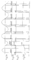
- Fig. 1 represents an elevator drive.
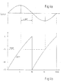
- Fig. 2a represents the motor current
- Fig. 2b represents the firing angle signal.
- Fig. 2c represents the signal used for measuring the zero point of the motor current.
- Fig. 2d represents the correction signal.
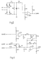
- Fig. 3 illustrates the generation of the firing angle signal.
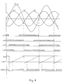
- Figs. 4a and 4b illustrate the synchronization of the firing angle signal.
- Fig. 5 illustrates the generation of the signal measuring the zero point of the motor current.
- Fig. 6 illustrates the generation of the correction signal.
- Fig. 7 shows a block diagram of a motor speed regulator utilizing a speed reference correction according to the invention.
- Fig. 8 shows the interdependence of the signals used for generating the firing angle signal.
- a squirrel-cage motor (M) 1 rotates a traction sheave 2 driving an elevator car 4 and counterweight 5 suspended on lifting ropes 3.
- the squirrel-cage motor is fed by a voltage converter connected to the voltages L1, L2, L3 of a three-phase mains network.
- the voltage converter provided with inverse-parallel connected thyristor pairs, is used for regulating the stator voltage of the motor, the thyristors in the power stage 6 are controlled by a control unit 7.
- the rotational speed of the motor is measured by a tachometer generator (TG) 8, and the phase current before the converter is measured by a current sensor 9 connected to phase L1.
- TG tachometer generator
- the control unit 7 adjusts the speed reference to a value at which the firing angle corresponds to the zero point of a sinusoidal motor current, i.e. to the so-called cos ⁇ value when the elevator speed is near its maximum value, in other words, when the elevator speed exceeds 80% of its nominal top speed.
- Fig. 2a represents the motor current I.
- the firing angle of the thyristors is set to an arbitrary value the current is intermittent, as shown in the left part of Fig. 2a.
- the pulse-shaped firing angle signal ANGLE shown in Fig. 2b is fixed to the cos ⁇ point.
- the pulse-shaped signal CURRE measuring the zero point of the motor current (Fig. 2c) is a narrow pulse, the motor current zero point occurring at the middle of the "window" formed by this pulse.
- the speed reference correction signal CORR (Fig. 2d) corrects the speed reference during the current signal until the current becomes sinusoidal.
- Fig. 3 shows the circuit used for generating the firing angle signal ANGLE.
- pulse-shaped voltages L1P, L1N, L3P and L3N are used (see Fig. 8). These signals are produced from the phase voltages, of which the pulse L1P is obtained when the positive phase voltage L1 is higher than the other phases voltages and, similarly, L1N is obtained when when the negative phase voltage L1 is lower the other phase voltages
- the voltage pulses L3P and L3N are obtained in the same way.
- These voltages are passed via diodes D1 D4 to the junction of resistors R1 and R2 and further through resistor R2 to the(-)input of an operational amplifier OP1.
- This input is connected to ground via capacitor C1, and resistor R1 is connected to the positive control voltage +V.
- the (+) input of the operational amplifier is also connected to this voltage via resistor R3.
- the (+ )input is connected to a voltage divider resistor R4 and a filtering capacitor C2.
- the signal obtained from the operational amplifier is passed via diode D5 and resistor R5 to the (+)input of another operational amplifier OP2, which is also connected to the negative control voltage -V via capacitor C3 and to the positive control voltage +V via variable resistor R6 and resistor R7 connected in series.
- Fig. 4a represents the main voltage UL1L3 and Fig. 4b represents the sawtooth voltage UC3 produced across capacitor C3 by the integrator consisting of resistor R5 and capacitor C3, this voltage being synchronized with the mains voltages.
- the (-)input of the operational amplifier OP2 is fed by a firing reference signal TREF, which is compared with the sawtooth wave UC3 to set the firing angle e.g. to approx. 90° as in Fig.4a (or to another value as in Fig. 8).
- the result of the comparison is obtained as firing angle signal ANGLE from the output of operational amplifier OP2, which is also connected to the positive control voltage +V via resistor R7 and to the negative control voltage -V via capacitor C4.
- the signal CURRE generated by the circuit in Fig. 5 is used to measure the zero point of the motor current signal to be measured is applied to the input terminals M1 and M2 of a diode bridge rectifier D6 - D9.
- the signal is passed via fuse F1, resistor R8 and capacitor C5, connected in parallel, and resistor R9 to the (-)input of operational amplifier OP3.
- the positive input is fed by a reference voltage produced from the positive control voltage +V by means of a voltage divider consisting of resistors R10 and R11.
- the reference voltage defines the minimum motor current above which a CURRE signal is produced.
- the above-mentioned CURRE signal is obtained from the output of the operational amplifier, which is connected to the positive control voltage +V via resistor R12.
- Fig. 6 shows an integrating circuit which is needed for the generation of the correction signal CORR.
- the main parts of the integrator are operational amplifier OP4, resistors R13 and R17 and capacitor C9.
- the integrator is reset by a FET Q1 connected across capacitor C9 and resistor R17.
- the FET has a control resistor R14 connected to its gate, and it is controlled by a signal PSPEED proportional to the motor speed, which is applied to the (-)input of operational amplifier OP5.
- the positive input is fed by a reference voltage produced via voltage division by resistors R16 and R17.
- the output of the operational amplifier is passed via filtering capacitor C7 and diode D10 to the gate G of FET Q1.
- Capacitors C6, C8 and C10 are filtering capacitors connected to the operational amplifier.
- the signal CURRE is applied via diode D11 to the gate of FET Q2.
- the gate of this FET is connected to a control resistor R19 and its D-electrode is connected to a resistor connected to ground.
- the firing angle signal ANGLE is applied via FET Q2 to the (-)input of operational amplifier OP4.
- the integrator is set to a point where the firing angle signal ANGLE is at the middle of the current signal CURRE measuring the zero point of the motor current. If the firing angle is on the trailing edge of the zero point pulse, this means that the current has not yet reached a sinusoidal form, so the speed reference is increased by increasing the CORR signal. Consequently, the firing angle is increased until the current becomes sinusoidal. On the other hand, if the firing angle has become too large, i.e. the regulation system is saturated, the firing angle will be on the leading edge of the zero point pulse. In this case, the speed reference is reduced by lowering the CORR signal.
- Fig. 7 shows a block diagram of a motor speed regulator utilizing a speed reference correction according to the invention.
- the firing signal ANGLE for the thyristors is produced by correcting the basic speed reference value with a correction signal CORR.
Landscapes
- Engineering & Computer Science (AREA)
- Automation & Control Theory (AREA)
- Power Engineering (AREA)
- Control Of Ac Motors In General (AREA)
- Control Of Electric Motors In General (AREA)
- Control Of Direct Current Motors (AREA)
- Control Of Stepping Motors (AREA)
- Amplifiers (AREA)
- Digital Magnetic Recording (AREA)
- Transmission Systems Not Characterized By The Medium Used For Transmission (AREA)
- Compression Or Coding Systems Of Tv Signals (AREA)
Claims (5)
- Verfahren zum Regulieren des Geschwindigkeits-Sollwertes eines Kurzschlußläufer-Aufzugmotors (1), der durch einen mit Halbleiterschaltern versehenen Spannungswandler (6,7) gespeist wird,
dadurch gekennzeichnet,
daß der Geschwindigkeits-Sollwert durch Verwendung eines Geschwindigkeits-Sollwert-Korrektursignals (CORR) geregelt wird, welcher den Geschwindigkeits-Sollwert auf einen Wert einstellt, bei welchem der Zündwinkel der Halbleiterschalter zum Nullpunkt des sinusförmigen Motorstroms korreliert ist. - Verfahren nach Anspruch 1,
dadurch gekennzeichnet,
daß das Korrektursignal (CORR) durch einen integrierenden Regler (OP4, R13, R17, C9) generiert wird. - Verfahren nach Anspruch 1 oder 2, bei welchem die Drehzahl des Motors gemessen wird,
dadurch gekennzeichnet,
daß der für die Generierung des Korrektursignals verwendete integrierende Regler arbeitet, wenn die Drehzahl des Motors zumindest nahe der nominalen Höchstdrehzahl ist, und daß, wenn die Drehzahl des Motors geringer ist, ein zur Drehzahl proportionales Signal den Regler zurücksetzt, und daß das Korrektursignal (CORR) aus einem Zündwinkelsignal (ANGLE) generiert wird, welches zum Zündwinkel der Halbleiterschalter korreliert ist. - Verfahren nach einem der vorhergehenden Ansprüche, bei welchem Verfahren der Motorstrom gemessen wird,
dadurch gekennzeichnet,
daß, wenn der Motorstrom einen bestimmten Wert unterschreitet, ein Signal (CURRE) generiert wird, das den Zugang des Zündwinkelsignals (ANGLE) zum Integrator verhindert, in welchem Fall das Korrektursignal (CORR) unverändert bleibt, und wenn der Strom einen gewissen Wert überschreitet, das Signal (CURRE) die Zuleitung des Zündwinkelsignals (ANGLE) in den Integrator zur Einstellung des Geschwindigkeits-Sollwertes ermöglicht. - Verfahren nach einem der vorhergehenden Ansprüche,
dadurch gekennzeichnet,
daß, wenn das Zündsignal auf der rückwärtigen Flanke des den Nullpunkt anzeigenden Signals (CURRE) liegt, der Geschwindigkeits-Sollwert durch Erhöhung des Korrektursignals (CORR) erhöht wird, und wenn der Zündwinkel auf der vorderen Kante des Impulses des den Nullpunkt anzeigenden Signals (CURRE) liegt, der Geschwindigkeits-Sollwert verringert wird, indem das Korrektursignal (CORR) verringert wird, in welchem Fall der Zündwinkel reduziert wird.
Applications Claiming Priority (2)
| Application Number | Priority Date | Filing Date | Title |
|---|---|---|---|
| FI901335 | 1990-03-16 | ||
| FI901335A FI88790C (fi) | 1990-03-16 | 1990-03-16 | Foerfarande foer reglering av hastighetsboervaerde av en spaenningreglerad kortsluten vaexelstroemsmotor i en hiss |
Publications (3)
| Publication Number | Publication Date |
|---|---|
| EP0446957A2 EP0446957A2 (de) | 1991-09-18 |
| EP0446957A3 EP0446957A3 (en) | 1992-12-30 |
| EP0446957B1 true EP0446957B1 (de) | 1994-11-30 |
Family
ID=8530078
Family Applications (1)
| Application Number | Title | Priority Date | Filing Date |
|---|---|---|---|
| EP91104180A Expired - Lifetime EP0446957B1 (de) | 1990-03-16 | 1991-03-18 | Prozedur zur Regelung der Sollgeschwindigkeit eines spannungsgeregelten Kurzschlussläufermotors |
Country Status (6)
| Country | Link |
|---|---|
| EP (1) | EP0446957B1 (de) |
| AT (1) | ATE114893T1 (de) |
| BR (1) | BR9101040A (de) |
| DE (1) | DE69105313T2 (de) |
| ES (1) | ES2065569T3 (de) |
| FI (1) | FI88790C (de) |
Families Citing this family (2)
| Publication number | Priority date | Publication date | Assignee | Title |
|---|---|---|---|---|
| JPH0678582A (ja) * | 1992-08-21 | 1994-03-18 | Sanyo Electric Co Ltd | 圧縮機の運転制御方法 |
| DK171689B1 (da) * | 1993-09-01 | 1997-03-10 | Dancontrol Eng As | Fremgangsmåde til regulering af en elektrisk kobling for sammenkobling af et vekselspændingsnet med en asynkron generator samt kobling |
Family Cites Families (3)
| Publication number | Priority date | Publication date | Assignee | Title |
|---|---|---|---|---|
| GB1524298A (en) * | 1975-04-03 | 1978-09-13 | Otis Elevator Japan | Control apparatus for an elevator system |
| GB1513356A (en) * | 1976-05-03 | 1978-06-07 | Mitsubishi Electric Corp | Speed control system for induction motor |
| JPS571175A (en) * | 1980-05-28 | 1982-01-06 | Mitsubishi Electric Corp | Controller for speed of elevator |
-
1990
- 1990-03-16 FI FI901335A patent/FI88790C/fi not_active IP Right Cessation
-
1991
- 1991-03-15 BR BR919101040A patent/BR9101040A/pt not_active IP Right Cessation
- 1991-03-18 DE DE69105313T patent/DE69105313T2/de not_active Expired - Fee Related
- 1991-03-18 EP EP91104180A patent/EP0446957B1/de not_active Expired - Lifetime
- 1991-03-18 ES ES91104180T patent/ES2065569T3/es not_active Expired - Lifetime
- 1991-03-18 AT AT91104180T patent/ATE114893T1/de not_active IP Right Cessation
Also Published As
| Publication number | Publication date |
|---|---|
| EP0446957A2 (de) | 1991-09-18 |
| BR9101040A (pt) | 1991-11-05 |
| DE69105313D1 (de) | 1995-01-12 |
| FI88790C (fi) | 1993-07-12 |
| EP0446957A3 (en) | 1992-12-30 |
| ES2065569T3 (es) | 1995-02-16 |
| FI88790B (fi) | 1993-03-31 |
| DE69105313T2 (de) | 1995-04-06 |
| FI901335A0 (fi) | 1990-03-16 |
| ATE114893T1 (de) | 1994-12-15 |
| FI901335L (fi) | 1991-09-17 |
Similar Documents
| Publication | Publication Date | Title |
|---|---|---|
| AU589803B2 (en) | Alternating current motor control apparatus | |
| EP0159000B1 (de) | Verfahren und Gerät zur Steuerung von pulsbreitenmodulierten Wechselrichtern | |
| US5932979A (en) | PWM speed-control apparatus for elevators | |
| US4276504A (en) | Control device for commutatorless motor | |
| EP0105215B1 (de) | Regelgerät für Wechselstrommotoren | |
| CA1280156C (en) | Inverter control apparatus for elevator motor | |
| JPS5930040B2 (ja) | 回転数を制御可能な非同期電動機を作動させるためのインバ−タ回路 | |
| KR0134984B1 (ko) | 모우터 제어 장치 | |
| HK1004040A1 (en) | Inverter control apparatus | |
| EP0446957B1 (de) | Prozedur zur Regelung der Sollgeschwindigkeit eines spannungsgeregelten Kurzschlussläufermotors | |
| JPH0813194B2 (ja) | エレベ−タの制御装置 | |
| EP0144161A2 (de) | Steuer- und Regelsystem für einen Wechselstrom-Motor | |
| US4058755A (en) | Kramer system utilizing a commutatorless motor | |
| EP0602490A2 (de) | Verfahren und Vorrichtung zur Schlupfkompensation einer Induktionsmaschine | |
| JPS57180395A (en) | Voltage controller for inverter | |
| JPH08208140A (ja) | エレベータの制御装置 | |
| JP3081505B2 (ja) | エレベータモータの調節装置 | |
| EP1163181A1 (de) | Dynamische bremsvorrichtung mit geschwindigkeitsregelung für aufzugskabine | |
| US4263541A (en) | Field control system for controlling induction machines | |
| JP2935583B2 (ja) | エレベータ用インバータの速度制御装置 | |
| SU983961A1 (ru) | Многодвигательный электропривод | |
| SU922983A1 (ru) | Устройство для управления частотно-регулируемым электроприводом 1 | |
| KR0123002Y1 (ko) | 유도전동기의 제동회로 | |
| SU1112520A1 (ru) | Электропривод | |
| SU657560A1 (ru) | Устройство дл управлени торможением асинхронного короткозамкнутого двигател |
Legal Events
| Date | Code | Title | Description |
|---|---|---|---|
| PUAI | Public reference made under article 153(3) epc to a published international application that has entered the european phase |
Free format text: ORIGINAL CODE: 0009012 |
|
| AK | Designated contracting states |
Kind code of ref document: A2 Designated state(s): AT BE CH DE DK ES FR GB GR IT LI LU NL SE |
|
| PUAL | Search report despatched |
Free format text: ORIGINAL CODE: 0009013 |
|
| AK | Designated contracting states |
Kind code of ref document: A3 Designated state(s): AT BE CH DE DK ES FR GB GR IT LI LU NL SE |
|
| 17P | Request for examination filed |
Effective date: 19930331 |
|
| 17Q | First examination report despatched |
Effective date: 19931230 |
|
| GRAA | (expected) grant |
Free format text: ORIGINAL CODE: 0009210 |
|
| AK | Designated contracting states |
Kind code of ref document: B1 Designated state(s): AT BE CH DE DK ES FR GB GR IT LI LU NL SE |
|
| PG25 | Lapsed in a contracting state [announced via postgrant information from national office to epo] |
Ref country code: GR Free format text: LAPSE BECAUSE OF FAILURE TO SUBMIT A TRANSLATION OF THE DESCRIPTION OR TO PAY THE FEE WITHIN THE PRESCRIBED TIME-LIMIT Effective date: 19941130 Ref country code: DK Effective date: 19941130 |
|
| REF | Corresponds to: |
Ref document number: 114893 Country of ref document: AT Date of ref document: 19941215 Kind code of ref document: T |
|
| REF | Corresponds to: |
Ref document number: 69105313 Country of ref document: DE Date of ref document: 19950112 |
|
| ITF | It: translation for a ep patent filed | ||
| ET | Fr: translation filed | ||
| REG | Reference to a national code |
Ref country code: ES Ref legal event code: FG2A Ref document number: 2065569 Country of ref document: ES Kind code of ref document: T3 |
|
| PG25 | Lapsed in a contracting state [announced via postgrant information from national office to epo] |
Ref country code: LU Free format text: LAPSE BECAUSE OF NON-PAYMENT OF DUE FEES Effective date: 19950331 |
|
| PLBE | No opposition filed within time limit |
Free format text: ORIGINAL CODE: 0009261 |
|
| STAA | Information on the status of an ep patent application or granted ep patent |
Free format text: STATUS: NO OPPOSITION FILED WITHIN TIME LIMIT |
|
| 26N | No opposition filed | ||
| PGFP | Annual fee paid to national office [announced via postgrant information from national office to epo] |
Ref country code: AT Payment date: 19980212 Year of fee payment: 8 |
|
| PGFP | Annual fee paid to national office [announced via postgrant information from national office to epo] |
Ref country code: SE Payment date: 19980217 Year of fee payment: 8 |
|
| PGFP | Annual fee paid to national office [announced via postgrant information from national office to epo] |
Ref country code: CH Payment date: 19980226 Year of fee payment: 8 |
|
| PGFP | Annual fee paid to national office [announced via postgrant information from national office to epo] |
Ref country code: ES Payment date: 19980311 Year of fee payment: 8 |
|
| PGFP | Annual fee paid to national office [announced via postgrant information from national office to epo] |
Ref country code: BE Payment date: 19980320 Year of fee payment: 8 |
|
| PG25 | Lapsed in a contracting state [announced via postgrant information from national office to epo] |
Ref country code: AT Free format text: LAPSE BECAUSE OF NON-PAYMENT OF DUE FEES Effective date: 19990318 |
|
| PG25 | Lapsed in a contracting state [announced via postgrant information from national office to epo] |
Ref country code: SE Free format text: LAPSE BECAUSE OF NON-PAYMENT OF DUE FEES Effective date: 19990319 |
|
| PG25 | Lapsed in a contracting state [announced via postgrant information from national office to epo] |
Ref country code: ES Free format text: THE PATENT HAS BEEN ANNULLED BY A DECISION OF A NATIONAL AUTHORITY Effective date: 19990320 |
|
| PG25 | Lapsed in a contracting state [announced via postgrant information from national office to epo] |
Ref country code: LI Free format text: LAPSE BECAUSE OF NON-PAYMENT OF DUE FEES Effective date: 19990331 Ref country code: CH Free format text: LAPSE BECAUSE OF NON-PAYMENT OF DUE FEES Effective date: 19990331 Ref country code: BE Free format text: LAPSE BECAUSE OF NON-PAYMENT OF DUE FEES Effective date: 19990331 |
|
| BERE | Be: lapsed |
Owner name: KONE ELEVATOR G.M.B.H. Effective date: 19990331 |
|
| EUG | Se: european patent has lapsed |
Ref document number: 91104180.4 |
|
| REG | Reference to a national code |
Ref country code: CH Ref legal event code: PL |
|
| EUG | Se: european patent has lapsed |
Ref document number: 91104180.4 |
|
| REG | Reference to a national code |
Ref country code: ES Ref legal event code: FD2A Effective date: 20010604 |
|
| REG | Reference to a national code |
Ref country code: GB Ref legal event code: IF02 |
|
| PGFP | Annual fee paid to national office [announced via postgrant information from national office to epo] |
Ref country code: NL Payment date: 20020225 Year of fee payment: 12 |
|
| REG | Reference to a national code |
Ref country code: GB Ref legal event code: 732E |
|
| PG25 | Lapsed in a contracting state [announced via postgrant information from national office to epo] |
Ref country code: NL Free format text: LAPSE BECAUSE OF NON-PAYMENT OF DUE FEES Effective date: 20031001 |
|
| NLV4 | Nl: lapsed or anulled due to non-payment of the annual fee |
Effective date: 20031001 |
|
| REG | Reference to a national code |
Ref country code: FR Ref legal event code: TP Ref country code: FR Ref legal event code: CA |
|
| PGFP | Annual fee paid to national office [announced via postgrant information from national office to epo] |
Ref country code: FR Payment date: 20040209 Year of fee payment: 14 |
|
| PGFP | Annual fee paid to national office [announced via postgrant information from national office to epo] |
Ref country code: GB Payment date: 20040212 Year of fee payment: 14 |
|
| PGFP | Annual fee paid to national office [announced via postgrant information from national office to epo] |
Ref country code: DE Payment date: 20040224 Year of fee payment: 14 |
|
| PG25 | Lapsed in a contracting state [announced via postgrant information from national office to epo] |
Ref country code: IT Free format text: LAPSE BECAUSE OF NON-PAYMENT OF DUE FEES;WARNING: LAPSES OF ITALIAN PATENTS WITH EFFECTIVE DATE BEFORE 2007 MAY HAVE OCCURRED AT ANY TIME BEFORE 2007. THE CORRECT EFFECTIVE DATE MAY BE DIFFERENT FROM THE ONE RECORDED. Effective date: 20050318 Ref country code: GB Free format text: LAPSE BECAUSE OF NON-PAYMENT OF DUE FEES Effective date: 20050318 |
|
| PG25 | Lapsed in a contracting state [announced via postgrant information from national office to epo] |
Ref country code: DE Free format text: LAPSE BECAUSE OF NON-PAYMENT OF DUE FEES Effective date: 20051001 |
|
| GBPC | Gb: european patent ceased through non-payment of renewal fee |
Effective date: 20050318 |
|
| PG25 | Lapsed in a contracting state [announced via postgrant information from national office to epo] |
Ref country code: FR Free format text: LAPSE BECAUSE OF NON-PAYMENT OF DUE FEES Effective date: 20051130 |
|
| REG | Reference to a national code |
Ref country code: FR Ref legal event code: ST Effective date: 20051130 |