EP0446890B1 - Befestigungsvorrichtung - Google Patents
Befestigungsvorrichtung Download PDFInfo
- Publication number
- EP0446890B1 EP0446890B1 EP91103830A EP91103830A EP0446890B1 EP 0446890 B1 EP0446890 B1 EP 0446890B1 EP 91103830 A EP91103830 A EP 91103830A EP 91103830 A EP91103830 A EP 91103830A EP 0446890 B1 EP0446890 B1 EP 0446890B1
- Authority
- EP
- European Patent Office
- Prior art keywords
- load
- distribution plate
- connecting device
- edge
- lever
- Prior art date
- Legal status (The legal status is an assumption and is not a legal conclusion. Google has not performed a legal analysis and makes no representation as to the accuracy of the status listed.)
- Expired - Lifetime
Links
- 238000007789 sealing Methods 0.000 claims description 27
- 230000000694 effects Effects 0.000 claims description 5
- 230000007423 decrease Effects 0.000 claims description 4
- 238000009740 moulding (composite fabrication) Methods 0.000 claims 1
- 239000012528 membrane Substances 0.000 description 13
- 239000011324 bead Substances 0.000 description 3
- 230000002349 favourable effect Effects 0.000 description 3
- 238000005452 bending Methods 0.000 description 2
- 238000009413 insulation Methods 0.000 description 2
- 238000003466 welding Methods 0.000 description 2
- 230000000284 resting effect Effects 0.000 description 1
- 238000004078 waterproofing Methods 0.000 description 1
Images

Classifications
-
- E—FIXED CONSTRUCTIONS
- E04—BUILDING
- E04D—ROOF COVERINGS; SKY-LIGHTS; GUTTERS; ROOF-WORKING TOOLS
- E04D5/00—Roof covering by making use of flexible material, e.g. supplied in roll form
- E04D5/14—Fastening means therefor
- E04D5/141—Fastening means therefor characterised by the location of the fastening means
- E04D5/142—Fastening means therefor characterised by the location of the fastening means along the edge of the flexible material
-
- E—FIXED CONSTRUCTIONS
- E04—BUILDING
- E04D—ROOF COVERINGS; SKY-LIGHTS; GUTTERS; ROOF-WORKING TOOLS
- E04D5/00—Roof covering by making use of flexible material, e.g. supplied in roll form
- E04D5/14—Fastening means therefor
- E04D5/144—Mechanical fastening means
- E04D5/145—Discrete fastening means, e.g. discs or clips
Definitions
- the invention relates to a fastening device for securing the position of loosely laid mechanically fastened sealing sheets, in particular roof sealing sheets, of the type specified in the preamble of claim 1.
- Roof sealing sheets are often laid loosely on flat or slightly inclined roof surfaces and mechanically fastened to prevent them from lifting under wind suction loads.
- this mechanical fastening is carried out point by point by means of a fastening means, generally a screw, and by means of a receiving element Load distributor plate near the edge of the track.
- the roofing membrane subsequently laid is then tightly fastened to cover the edge of the membrane perforated by the fastening.
- the tight connection can be made by hot air welding or source welding.
- rectangular, square or circular load distribution plates are used, as is known, for example, from EP-A-0 283 184, but also from DE-A-34 20 863 (FIG. 3).
- the fastener that is to say the screw
- the fastener is passed through a hole arranged centrally in the load distributor plate and anchored in the substructure on which the sealing sheets rest.
- This substructure often consists of profiled sheets.
- the sealing membranes are raised, whereby the load distributor plate is loaded on one side.
- This load causes a tilting movement, by means of which the load distributor plate is raised somewhat to its edge, which faces the edge of the overlapping web and runs parallel to this.
- the central passage of the fastening screw through the load distribution plate leads to a tensile force in the fastening screw which corresponds approximately to twice the attacking wind suction force and which must be introduced into the base.
- the invention is therefore based on the object to reduce the load to be absorbed by the fastener and the support and a relatively low clamping effect between the tilted load distribution plate when fastening the specified type and to avoid the edge of the underlying membrane.
- the advantages achieved by the invention are based on the asymmetrical shape of the load distributor plate with respect to the tilting axis (significant decrease in the width of the load distributor plate from its edge near the fastening means towards the opposite edge) in connection with the eccentric arrangement of the fastening means, which results in a particularly favorable surface pressure between the load distributor plate and the covered edge of the geomembrane is reached.
- Loads resulting from the sealing sheeting taking off under the influence of wind are absorbed in such a way that only low tensile forces are generated in the fastening means and transmitted to the substructure.
- it is avoided that the sealing sheet is no longer held sufficiently on the base by the load distribution plate and there is therefore a risk that the sealing sheet could tear out.
- the load distribution plate can be manufactured particularly easily and economically and, moreover, can cope with almost any load situation.
- An all-round stiffening bead in the edge area of the load distributor plate ensures additional mechanical strength while improving the clamping effect.
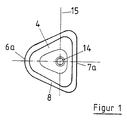
- a load distributor plate 4 with the shape shown in FIG. 1 has proven itself in tests in which a roof cutout has been exposed to a simulated wind load.
- This load distribution plate 4 is essentially triangular, i.e. its width decreases significantly from the edge 7a to the opposite edge 6a. In its edge area, the load distributor plate 4 has a circumferential stiffening bead 8.
- FIG. 2 shows a typical roof structure with a substructure 1, which is formed by a profiled sheet, a thermal insulation layer 2 resting on the substructure 1 and a first roof sealing membrane 3, the edge region of which is secured by means of the load distribution plate 4 and the fastening means 5 anchored in the substructure 1 is clamped on the thermal insulation layer 2. This attachment is therefore on the edge region of the sealing membrane 3.
- an overlapping second roof sealing membrane 3a extends from the left over the fastening and is connected with its edge on the right side of the fastening to the upper side of the first sealing membrane 3, for example hot air welded or source welded.
- the two sealing sheets 3, 3a deform upward in the form of a membrane, as is indicated in FIG. 2.
- the load distributor plate 4 is loaded on one side, namely by a force acting on the load distributor plate 4 on its edge 7a running parallel to the two roof sealing sheets 3, 3a. This creates a tilting moment around the tilting axis 15 of the load distributor plate 4 running through the hole 14 (see FIG. 1).
- the load distribution plate 4 shown in FIG. 1 is thus arranged between the lower edge of the first sealing sheet 3 and the overlapping edge of the second sealing sheet 3a such that its edge 7a extends parallel to the edges of the two sealing sheets 3, 3a.
- the hole 14 and thus the fastening means 5 are located off-center in the load distribution plate 4, namely closer to the edge 7a, which faces the connection area between the edges of the two roofing sheets 3, 3a.
- the distance from the hole 14 or from the fastening means 5 to the opposite edge 6a of the load distributor plate 4 forming a tip is therefore substantially greater than the distance from the edge 7a to the hole 14, as a result of which there is a favorable surface pressure in the region of the edge 7a the load distribution plate 4 and the covered edge of the first sealing sheet 3 comes.
- the tensile force to be absorbed by the fastening means 5 and by the substructure 1, which results from the wind suction load on the sealing sheets 3, 3a and Suction force acting on the edge 7a of the load distributor plate 4 is less than when the hole 14 is arranged centrally in the load distributor plate 4.
- the above-mentioned favorable surface pressure is achieved in particular in that the load distributor plate 4 is asymmetrical to an axis which runs parallel to the longitudinal direction of the web (tilt axis 15).
- the width of the load distributor plate 4, measured in the longitudinal direction of the web, clearly decreases from its edge 7a, which is closer to the fastening means 5, to the opposite edge 6a, and thus leads to the desired good surface pressure in connection with the lever action described.
- the load distributor plate 4 can be provided with additional deformations in addition to the stiffening bead 8, which improve the distribution of the loads that occur and increase the rigidity of the load distributor plate 4 in relation to the bending loads that occur.
Landscapes
- Engineering & Computer Science (AREA)
- Architecture (AREA)
- Civil Engineering (AREA)
- Structural Engineering (AREA)
- Mechanical Engineering (AREA)
- Roof Covering Using Slabs Or Stiff Sheets (AREA)
Applications Claiming Priority (2)
| Application Number | Priority Date | Filing Date | Title |
|---|---|---|---|
| DE4008517A DE4008517C1 (enExample) | 1990-03-16 | 1990-03-16 | |
| DE4008517 | 1990-03-16 |
Publications (2)
| Publication Number | Publication Date |
|---|---|
| EP0446890A1 EP0446890A1 (de) | 1991-09-18 |
| EP0446890B1 true EP0446890B1 (de) | 1994-11-30 |
Family
ID=6402401
Family Applications (1)
| Application Number | Title | Priority Date | Filing Date |
|---|---|---|---|
| EP91103830A Expired - Lifetime EP0446890B1 (de) | 1990-03-16 | 1991-03-13 | Befestigungsvorrichtung |
Country Status (3)
| Country | Link |
|---|---|
| US (1) | US5171116A (enExample) |
| EP (1) | EP0446890B1 (enExample) |
| DE (2) | DE4008517C1 (enExample) |
Families Citing this family (6)
| Publication number | Priority date | Publication date | Assignee | Title |
|---|---|---|---|---|
| US5797232A (en) * | 1996-08-15 | 1998-08-25 | Illinois Tool Works Inc. | Gripping plate for attaching roofing membrane |
| US6205730B1 (en) | 1999-01-13 | 2001-03-27 | Illinois Tool Works Inc | Roofing plate for securing roofing membrane |
| US6689449B2 (en) * | 2002-01-04 | 2004-02-10 | Illinois Tool Works Inc. | Roof decking membrane welding system and method |
| US7178306B2 (en) * | 2003-09-30 | 2007-02-20 | Duro-Last, Inc. | Single ply roofing systems and methods of constructing them |
| US8590245B2 (en) * | 2009-06-04 | 2013-11-26 | Owens Corning Intellectual Capital, Llc | Banded liner system for metal buildings |
| US9309911B1 (en) * | 2012-01-23 | 2016-04-12 | K & R Industries Inc. | Cap nail |
Family Cites Families (12)
| Publication number | Priority date | Publication date | Assignee | Title |
|---|---|---|---|---|
| FR884660A (fr) * | 1942-04-01 | 1943-08-24 | Rondelle destinée en particulier à la fixation des tôles ondulées | |
| FR1499940A (fr) * | 1966-04-22 | 1967-11-03 | Dispositif de soutènement des parois rocheuses | |
| DE2636663A1 (de) * | 1976-08-14 | 1978-02-16 | Ruhrkohle Ag | Befestigungslasche aus blech zum festlegen von insbesondere aus thermoplastischem werkstoff bestehenden dichtungsbahnen |
| DE3236161C2 (de) * | 1982-09-30 | 1984-11-22 | Trilux-Lenze Gmbh + Co Kg, 5760 Arnsberg | Geschlitzte Unterlegscheibe zum Aufstecken auf den durch ein Schraubenloch eines Leuchtengehäuses ragenden Schaft einer Befestigungsschraube |
| AT380051B (de) * | 1983-06-22 | 1986-04-10 | Sfs Stadler Ag | Vorrichtung zum befestigen von dachbahnen auf weichem isoliermaterial an einer festen unterlage |
| US4780039A (en) * | 1983-09-19 | 1988-10-25 | The B. F. Goodrich Company | Fastener plate |
| US4630984A (en) * | 1984-01-27 | 1986-12-23 | Elco Industries, Inc. | Assembly for fastening a layer of compressible material to a rigid member |
| US4787188A (en) * | 1986-01-02 | 1988-11-29 | Engineered Construction Components | Stress plate and method of using same for securing a roof membrane to a roof deck |
| US4631887A (en) * | 1986-01-31 | 1986-12-30 | Francovitch Thomas F | Non-penetrating roof membrane anchoring system |
| CH676133A5 (enExample) * | 1986-03-12 | 1990-12-14 | Protan As | |
| US4718211A (en) * | 1986-10-29 | 1988-01-12 | Greenstreak Plastic Products Company | Batten bar for single ply membrane used on roofs |
| US4726164A (en) * | 1987-03-16 | 1988-02-23 | Elco Industries, Inc. | Fastener assembly for a roof membrane |
-
1990
- 1990-03-16 DE DE4008517A patent/DE4008517C1/de not_active Expired - Fee Related
-
1991
- 1991-03-13 DE DE59103612T patent/DE59103612D1/de not_active Expired - Fee Related
- 1991-03-13 EP EP91103830A patent/EP0446890B1/de not_active Expired - Lifetime
- 1991-03-15 US US07/670,290 patent/US5171116A/en not_active Expired - Fee Related
Also Published As
| Publication number | Publication date |
|---|---|
| DE4008517C1 (enExample) | 1991-09-05 |
| DE59103612D1 (de) | 1995-01-12 |
| EP0446890A1 (de) | 1991-09-18 |
| US5171116A (en) | 1992-12-15 |
Similar Documents
| Publication | Publication Date | Title |
|---|---|---|
| EP0733141B1 (de) | Grossflächige unterlegscheibe | |
| DE2636491A1 (de) | Vorrichtung zur verbindung aneinanderliegender kanten von dachplatten miteinander und mit einer dachkonstruktion | |
| EP0697267A1 (de) | Befestigungsvorrichtung für ein Werkzeug oder Werkstück | |
| CH664404A5 (de) | Befestigungsanordnung fuer schienen auf schwellen. | |
| DE3930327A1 (de) | Spannschlossmutter-befestigungsvorrichtung | |
| EP1389701B1 (de) | Mehrlagige Dichtung und Verfahren zum Verbinden der Lagen einer mehrlagigen Dichtung | |
| EP0446890B1 (de) | Befestigungsvorrichtung | |
| DE2626808C2 (de) | Vorrichtung zum Befestigen eines Plattenteils an einem Basisteil | |
| DE60005483T2 (de) | Türkonstruktion | |
| DE2628874C2 (de) | Vorrichtung zum Befestigen einer Schiene auf einem Träger, einer Schwelle o.dgl. | |
| DE3442407A1 (de) | Halteelement fuer selbsttragende bauelemente, wie dachelemente, wandverkleidungen und dergleichen | |
| EP0064290A1 (de) | Vorrichtung zur Halterung von Verkleidungsplatten und dgl. an Bauwerksteilen | |
| DE2543897B2 (de) | Vorrichtung zum Halten eines rohrförmigen Handlaufs | |
| DE4207445C2 (de) | Lastverteilerteller | |
| DE202023100435U1 (de) | Dachhaken | |
| DE69403629T2 (de) | Verankerungseinrichtung für dächer | |
| EP0506216A1 (de) | Befestigungsvorrichtung für Führungsschienen | |
| DE19652020C2 (de) | Durch Kraftschluß positionier- und fixierbare Flachdichtung | |
| EP0358132B1 (de) | Haltevorrichtung zum Verankern einer Membrane an einem ortsfesten Bauteil | |
| DE102004022276B4 (de) | Vorrichtung zur Befestigung von Dämmstoffelementen an ebenen Flächen | |
| DE3824630C2 (de) | Klemmverbindung für Gruben-Rinnenausbauprofile eines Gleitbogenausbaus | |
| EP0020916B1 (de) | Befestigungsvorrichtung | |
| DE19820958C2 (de) | Befestigungsvorrichtung zum Befestigen einer Abdichtschicht an einer Unterlage | |
| DE3524367A1 (de) | Klammereinheit zum befestigen von stehfalz-dachdeckungen | |
| DE365376T1 (de) | Anschluss eines kabels an eine elektrode einer folie, insbesondere heizfolie, mittels eindringendem kabelanschluss undplatte, bestehend aus einer vielzahl zusammenhaengender eindringender ecken. |
Legal Events
| Date | Code | Title | Description |
|---|---|---|---|
| PUAI | Public reference made under article 153(3) epc to a published international application that has entered the european phase |
Free format text: ORIGINAL CODE: 0009012 |
|
| AK | Designated contracting states |
Kind code of ref document: A1 Designated state(s): CH DE FR GB LI NL SE |
|
| 17P | Request for examination filed |
Effective date: 19920122 |
|
| 17Q | First examination report despatched |
Effective date: 19921008 |
|
| GRAA | (expected) grant |
Free format text: ORIGINAL CODE: 0009210 |
|
| AK | Designated contracting states |
Kind code of ref document: B1 Designated state(s): CH DE FR GB LI NL SE |
|
| GBT | Gb: translation of ep patent filed (gb section 77(6)(a)/1977) |
Effective date: 19941212 |
|
| REF | Corresponds to: |
Ref document number: 59103612 Country of ref document: DE Date of ref document: 19950112 |
|
| EAL | Se: european patent in force in sweden |
Ref document number: 91103830.5 |
|
| ET | Fr: translation filed | ||
| PLBE | No opposition filed within time limit |
Free format text: ORIGINAL CODE: 0009261 |
|
| STAA | Information on the status of an ep patent application or granted ep patent |
Free format text: STATUS: NO OPPOSITION FILED WITHIN TIME LIMIT |
|
| 26N | No opposition filed | ||
| PGFP | Annual fee paid to national office [announced via postgrant information from national office to epo] |
Ref country code: CH Payment date: 20000221 Year of fee payment: 10 |
|
| PGFP | Annual fee paid to national office [announced via postgrant information from national office to epo] |
Ref country code: SE Payment date: 20000224 Year of fee payment: 10 Ref country code: FR Payment date: 20000224 Year of fee payment: 10 Ref country code: DE Payment date: 20000224 Year of fee payment: 10 |
|
| PGFP | Annual fee paid to national office [announced via postgrant information from national office to epo] |
Ref country code: GB Payment date: 20010214 Year of fee payment: 11 |
|
| PGFP | Annual fee paid to national office [announced via postgrant information from national office to epo] |
Ref country code: NL Payment date: 20010228 Year of fee payment: 11 |
|
| PG25 | Lapsed in a contracting state [announced via postgrant information from national office to epo] |
Ref country code: SE Free format text: LAPSE BECAUSE OF NON-PAYMENT OF DUE FEES Effective date: 20010314 |
|
| PG25 | Lapsed in a contracting state [announced via postgrant information from national office to epo] |
Ref country code: NL Free format text: LAPSE BECAUSE OF NON-PAYMENT OF DUE FEES Effective date: 20010331 Ref country code: LI Free format text: LAPSE BECAUSE OF NON-PAYMENT OF DUE FEES Effective date: 20010331 Ref country code: CH Free format text: LAPSE BECAUSE OF NON-PAYMENT OF DUE FEES Effective date: 20010331 |
|
| EUG | Se: european patent has lapsed |
Ref document number: 91103830.5 |
|
| REG | Reference to a national code |
Ref country code: CH Ref legal event code: PL |
|
| PG25 | Lapsed in a contracting state [announced via postgrant information from national office to epo] |
Ref country code: FR Free format text: LAPSE BECAUSE OF NON-PAYMENT OF DUE FEES Effective date: 20011130 |
|
| NLV4 | Nl: lapsed or anulled due to non-payment of the annual fee |
Effective date: 20011001 |
|
| REG | Reference to a national code |
Ref country code: FR Ref legal event code: ST |
|
| PG25 | Lapsed in a contracting state [announced via postgrant information from national office to epo] |
Ref country code: DE Free format text: LAPSE BECAUSE OF NON-PAYMENT OF DUE FEES Effective date: 20020101 |
|
| REG | Reference to a national code |
Ref country code: GB Ref legal event code: IF02 |
|
| PG25 | Lapsed in a contracting state [announced via postgrant information from national office to epo] |
Ref country code: GB Free format text: LAPSE BECAUSE OF NON-PAYMENT OF DUE FEES Effective date: 20020313 |
|
| GBPC | Gb: european patent ceased through non-payment of renewal fee |
Effective date: 20020313 |