EP0446316B1 - Kleinventilator - Google Patents
Kleinventilator Download PDFInfo
- Publication number
- EP0446316B1 EP0446316B1 EP90913243A EP90913243A EP0446316B1 EP 0446316 B1 EP0446316 B1 EP 0446316B1 EP 90913243 A EP90913243 A EP 90913243A EP 90913243 A EP90913243 A EP 90913243A EP 0446316 B1 EP0446316 B1 EP 0446316B1
- Authority
- EP
- European Patent Office
- Prior art keywords
- fan
- fan wheel
- air
- hub
- impeller
- Prior art date
- Legal status (The legal status is an assumption and is not a legal conclusion. Google has not performed a legal analysis and makes no representation as to the accuracy of the status listed.)
- Expired - Lifetime
Links
- 230000001747 exhibiting effect Effects 0.000 claims 1
- 230000002349 favourable effect Effects 0.000 description 4
- BGPVFRJUHWVFKM-UHFFFAOYSA-N N1=C2C=CC=CC2=[N+]([O-])C1(CC1)CCC21N=C1C=CC=CC1=[N+]2[O-] Chemical compound N1=C2C=CC=CC2=[N+]([O-])C1(CC1)CCC21N=C1C=CC=CC1=[N+]2[O-] BGPVFRJUHWVFKM-UHFFFAOYSA-N 0.000 description 1
- 238000010276 construction Methods 0.000 description 1
- 238000001746 injection moulding Methods 0.000 description 1
- 238000004519 manufacturing process Methods 0.000 description 1
Images

Classifications
-
- F—MECHANICAL ENGINEERING; LIGHTING; HEATING; WEAPONS; BLASTING
- F04—POSITIVE - DISPLACEMENT MACHINES FOR LIQUIDS; PUMPS FOR LIQUIDS OR ELASTIC FLUIDS
- F04D—NON-POSITIVE-DISPLACEMENT PUMPS
- F04D25/00—Pumping installations or systems
- F04D25/02—Units comprising pumps and their driving means
- F04D25/06—Units comprising pumps and their driving means the pump being electrically driven
- F04D25/0606—Units comprising pumps and their driving means the pump being electrically driven the electric motor being specially adapted for integration in the pump
-
- F—MECHANICAL ENGINEERING; LIGHTING; HEATING; WEAPONS; BLASTING
- F04—POSITIVE - DISPLACEMENT MACHINES FOR LIQUIDS; PUMPS FOR LIQUIDS OR ELASTIC FLUIDS
- F04D—NON-POSITIVE-DISPLACEMENT PUMPS
- F04D29/00—Details, component parts, or accessories
- F04D29/26—Rotors specially for elastic fluids
- F04D29/32—Rotors specially for elastic fluids for axial flow pumps
- F04D29/325—Rotors specially for elastic fluids for axial flow pumps for axial flow fans
Definitions
- the invention relates to a small fan according to the preamble of independent claim 1.
- a small fan of this type has become known from the applicant's US-A-4,504,751.
- the electric motor is accommodated in the externally circular-cylindrical hub of a one-piece impeller, which enables particularly small external dimensions in the event of axial air outlet on the back of the air duct housing.
- This fan has therefore found many uses. In some applications, however, the noise that occurs is annoying.
- a diagonal fan is known from DE-A-29 44 183, in which, however, the jacket of the hub of the impeller is circular-conical or concave paraboloidal and which has a radial flow outlet. Since the motor is arranged separately from the wing on the back, a flat design as with the generic fan is fundamentally not possible.
- the applicant has now set itself the task of developing the generic fan in such a way that it has a higher output with the same external dimensions and at the same time is quieter and can be manufactured more cost-effectively.
- the small fan according to the invention has an approximately laminar flow. Since there is essentially no turbulence in the polluting air, it is considerably quieter. This is an improvement that has long been sought in this field.
- a particularly flat design with a favorable power density is achieved according to a development of the invention in that the impeller front edges and the hub front and the housing front lie approximately in the same plane.
- the small fan has a cuboidal air duct housing 2 with an outer part 2a and a circular recess 2f.
- a known electric motor 4 with electromagnetic coils 4a is attached to a molded-on base 2b.
- the arms 4c connect the electric motor 4 to the outer housing part 2a.
- An impeller 1 made of plastic is inserted into the recess 2f and rotatably mounted in the housing 2 by means of an axis 3 and a bearing 6.
- the shaft 3, which is fixedly connected to the impeller 1, is surrounded by an annular permanent magnet 5, which forms part of the electric motor 4.
- the impeller 1 preferably has five integrally formed blades 1 a, each of which has the same angle of attack ⁇ over the entire depth of the blade and thus parallel blade edges (FIG. 3). It has been shown that a particularly favorable ratio between volume flow and sound is achieved with a number of blades between 3 and 7.
- the wings are not twisted and have the same cross-section as shown in FIG. 3 up to their attachment point.
- the angle of attack is preferably about 30 °.
- the air enters the fan axially through the front face 2d of the fan and also leaves it in the axial direction through the rear face 2e.
- the inflow to the impeller and the outflow are therefore largely axial.
- the impeller 1, however, is flowed through diagonally as indicated by the flow lines 7.
- the hub 2d of the impeller 1 has a flat front surface 1c which lies approximately in one plane with the housing front 2d and the leading edge 1b of the wing.
- the flow surface 1e of the hub 1d adjoining the surface 1c has the shape shown in FIG. 1.
- the flow areas 1e and 1f of the vanes 1a result from the section according to FIG. 3.
- the hubs and vanes are designed such that the flow of air through the housing is laminar and essentially no pressure differences occur on the vanes in the radial direction.
Landscapes
- Engineering & Computer Science (AREA)
- Mechanical Engineering (AREA)
- General Engineering & Computer Science (AREA)
- Structures Of Non-Positive Displacement Pumps (AREA)
Abstract
Description
- Die Erfindung betrifft einen Kleinventilator nach dem Oberbegriff des unabhängigen Patentanspruchs 1.
- Ein Kleinventilator dieser Gattung ist durch die US-A-4,504,751 der Anmelderin bekannt geworden. Bei diesem ist der Elektromotor in der aussenseitig kreiszylindrischen Nabe eines einstückigen Flügelrades untergebracht, was bei axialem Luftaustritt auf der Rückseite des Luftführungsgehäuses besonders kleine Aussenabmessungen ermöglicht. Dieser Ventilator hat deshalb viele Anwendungen gefunden. Bei einigen Anwendungen sind jedoch die auftretenden Geräusche störend. Ferner ist durch die DE-A-29 44 183 ein Diagonalgebläse bekannt, bei dem jedoch der Mantel der Nabe des Flügelrades kreiskegelförmig oder konkav paraboloidisch ist und das einen radialen Strömungsaustritt besitzt. Da der Motor getrennt vom Flügel an der Rückseite angeordnet ist, ist eine flache Bauweise wie beim gattungsgemässen Ventilator grundsätzlich nicht möglich. Die Anmelderin hat sich nun die Aufgabe gestellt, den gattungsgemässen Ventilator dahingehend weiterzubilden, dass er bei gleichen Aussenmassen eine höhere Leistung aufweist und gleichzeitig leiser ist und kostengünstiger hergestellt werden kann. Dererfindungsgemässe Kleinventilatorweist im Gegensatz zum oben genannten Ventilator, der ein kleines Axialgebläse ist, einen angenähert laminaren Durchfluss auf. Da in der durchstörmenden Luft im wesentlichen somit keine Verwirbelungen auftreten, ist er wesentlich leiser. Damit wird eine auf diesem Fachgebiet seit langem angestrebte Verbesserung erreicht.
- Versuche haben nun gezeigt, dass beim erfindungsgemässen Ventilator die Leistungsdichte verglichen mit dem einen Axialventilator etwa um 30% höher ist. Obwohl seit langem bekannt ist, das meridianbeschleunigte Gebläse eine günstige Leistungsdichte aufweisen, hatte diese Erkenntnis bisher den Bau der Kleinventilatoren nicht beeinflusst. Wesentlich ist nun, dass die Flügel des Flügelrades nicht verwunden sind und jeweils über die ganze Flügeltiefe den gleichen Anstellwinkel aufweisen. Das Flügelrad kann deshalb bei einfacher Entformung einstückig und damit kostengünstig im Spritzgussverfahren hergestellt werden.
- Durch die Kombination der erfindungswesentlichen Merkmale wird somit bei einfacher Herstellung ein Ventilator mit günstigeren Betriebseigenschaften geschaffen.
- Eine besonders flache Bauweise bei günstiger Leistungsdichte wird nach einer Weiterbildung der Erfindung dadurch erreicht, dass die Flügelradvorderkanten und die Nabenfrontseite sowie die Gehäusefrontseite etwa in gleiche Ebene liegen.
- Ein Ausführungsbeispiel der Erfindung wird nachfolgend anhand der Zeichnungen näher erläutert. Es zeigen:
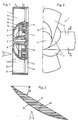
- Fig. 1 einen Schnitt durch einen erfindungsgemässen Kleinventilator,
- Fig. 2 eine Teilansicht eines Flügelrades,
- Fig. 3 einen Schnitt durch einen Flügel entlang der Linie 111-111 in Fig. 2, und
- Fig. 4 eine Ansicht des Luftführungsgehäuses.
- Der Kleinventilator weist ein quaderförmiges Luftführungsgehäuse 2 mit einem Aussenteil 2a und einer kreisrunden Ausnehmung 2f auf. Auf einem angeformten Boden 2b ist ein bekannter Elektromotor 4 mit Elektromagnetspulen 4a angebracht. Mit Armen 2c ist der Elektromotor 4 mit dem Gehäuseaussenteil 2a verbunden.
- Ein aus Kunststoff hergestelltes Flügelrad 1 ist in die Ausnehmung 2f eingesetzt und mittels einer Achse 3 und einem Lager 6 rotierbar im Gehäuse 2 gelagert. Die fest mit dem Flügelrad 1 verbundene Achse 3 ist von einem ringförmigen Dauermagneten 5 umgeben, der ein Bestanteil des Elektromotors 4 bildet.
- Wie insbesondere die Fig. 2 und 3 zeigen, besitzt das Flügelrad 1 vorzugsweise fünf angeformte Flügel 1a, die jeweils über die gesamte Flügeltiefe den gleichen Anstellwinkel a und somit parallele Schaufelkanten (Fig. 3) aufweisen. Es hat sich gezeigt, dass bei einer Flügelzahl zwischen 3 und 7 ein besonders günstiges Verhältnis zwischen Volumenstrom und Schall erreicht wird. Die Flügel sind nicht verwunden und besitzen bis zu ihrer Ansatzstelle den gleichen wie in Fig. 3 gezeigten Querschnitt. Der Anstellwinkel beträgt vorzugsweise etwa 30°. In der Darstellung nach Fig. 1 tritt die Luft durch die Gehäusefrontseite 2d axial in den Ventilator ein und verlässt diesen ebenfalls in axialer Richtung durch die Gehäuserückseite 2e. Die Zuströmung zum Laufrad und die Abströmung erfolgt somit weitgehend axial. Das Flügelrad 1 wird hingegen wie durch die Strömungslinien 7 angedeutet diagonal durchströmt.
- Die Nabe 2d des Flügelrades 1 weist eine ebene Frontfläche 1 c auf, die mit der Gehäusefrontseite 2d sowie den Flügelvorderkanten 1 b etwa in einer Ebene liegen. Die an die Fläche 1c anschliessende Strömungsfläche 1e der Nabe 1d weist die aus Fig. 1 ersichtliche Formgebung auf. Die Strömungsflächen 1e und 1f der Flügel 1a ergeben sich aus dem Schnitt gemäss Fig. 3. Naben und Flügel sind so ausgebildet, dass der Durchfluss der Luft durch das Gehäuse laminar ist und an den Flügeln in radialer Richtung im wesentlichen keine Druckunterschiede auftreten.
Claims (4)
Applications Claiming Priority (4)
| Application Number | Priority Date | Filing Date | Title |
|---|---|---|---|
| CH3540/89 | 1989-09-29 | ||
| CH354089 | 1989-09-29 | ||
| CH354089 | 1989-09-29 | ||
| PCT/CH1990/000223 WO1991005169A1 (de) | 1989-09-29 | 1990-09-20 | Kleinventilator |
Publications (3)
| Publication Number | Publication Date |
|---|---|
| EP0446316A1 EP0446316A1 (de) | 1991-09-18 |
| EP0446316B1 true EP0446316B1 (de) | 1994-02-02 |
| EP0446316B2 EP0446316B2 (de) | 2001-12-05 |
Family
ID=4258189
Family Applications (1)
| Application Number | Title | Priority Date | Filing Date |
|---|---|---|---|
| EP90913243A Expired - Lifetime EP0446316B2 (de) | 1989-09-29 | 1990-09-20 | Kleinventilator |
Country Status (6)
| Country | Link |
|---|---|
| US (1) | US5217351A (de) |
| EP (1) | EP0446316B2 (de) |
| JP (1) | JP3090216B2 (de) |
| DE (1) | DE59004520D1 (de) |
| HU (1) | HU210777B (de) |
| WO (1) | WO1991005169A1 (de) |
Families Citing this family (22)
| Publication number | Priority date | Publication date | Assignee | Title |
|---|---|---|---|---|
| DE4127134B4 (de) * | 1991-08-15 | 2004-07-08 | Papst Licensing Gmbh & Co. Kg | Diagonallüfter |
| KR970010561B1 (ko) * | 1994-04-18 | 1997-06-28 | 삼성전자 주식회사 | 정음형 송풍기 |
| JP2987133B2 (ja) | 1997-04-25 | 1999-12-06 | 日本電産コパル株式会社 | 軸流ファンと軸流ファンの羽根体の製造方法及び軸流ファンの羽根体の製造用金型 |
| JP3500292B2 (ja) * | 1998-01-30 | 2004-02-23 | 日本電産コパル株式会社 | 軸流ファン |
| FR2781843B1 (fr) * | 1998-07-28 | 2000-10-20 | Valeo Thermique Moteur Sa | Helice de ventilateur compacte optimisee |
| FR2812349B1 (fr) * | 2000-07-31 | 2003-01-24 | Jouan | Enceinte de travail a helice de mise en mouvement de son atmosphere et helice correspondante |
| US20030223865A1 (en) * | 2002-05-30 | 2003-12-04 | Sunonwealth Electric Machine Industry Co., Ltd. | Casing for a heat-dissipating fan |
| JP2004169680A (ja) * | 2002-11-18 | 2004-06-17 | Taida Electronic Ind Co Ltd | 羽根構造およびそれを用いた放熱装置 |
| FR2864368B1 (fr) * | 2003-12-19 | 2006-08-04 | Valeo Equip Electr Moteur | Dispositif de renforcement de la ventilation d'une machine electrique et machine electrique comportant un tel dispositif |
| CN100424360C (zh) * | 2004-02-11 | 2008-10-08 | 台达电子工业股份有限公司 | 风扇及其扇叶组件 |
| US20070031262A1 (en) * | 2005-08-04 | 2007-02-08 | Jinseok Kim | Computer cooling fan |
| TWI293106B (en) * | 2005-11-22 | 2008-02-01 | Sunonwealth Electr Mach Ind Co | Thin-type fan |
| TWI292014B (en) * | 2005-11-22 | 2008-01-01 | Sunonwealth Electr Mach Ind Co | Ultra thin-type fan |
| TW200732565A (en) * | 2006-02-21 | 2007-09-01 | Sunonwealth Electr Mach Ind Co | The structure of a small blower |
| TW200736507A (en) * | 2006-03-27 | 2007-10-01 | Sunonwealth Electr Mach Ind Co | A thin structure pattern of heat dissipation |
| TWI349515B (en) * | 2006-10-25 | 2011-09-21 | Delta Electronics Inc | Fan and fan frame thereof |
| US20080107366A1 (en) * | 2006-11-06 | 2008-05-08 | Zippy Technology Corp. | Air fan bearing structure |
| TWI328080B (en) * | 2007-03-30 | 2010-08-01 | Delta Electronics Inc | Fan and impeller thereof |
| JP2008267176A (ja) * | 2007-04-17 | 2008-11-06 | Sony Corp | 軸流ファン装置、ハウジング及び電子機器 |
| TWI373563B (en) * | 2008-06-03 | 2012-10-01 | Sunonwealth Electr Mach Ind Co | Brushless dc motor |
| WO2010028441A1 (en) * | 2008-09-11 | 2010-03-18 | Hunter Pacific International Pty Ltd | Extraction fan and rotor |
| US10034411B2 (en) * | 2015-09-25 | 2018-07-24 | Apple Inc. | Thermal flow assembly including integrated fan |
Family Cites Families (15)
| Publication number | Priority date | Publication date | Assignee | Title |
|---|---|---|---|---|
| US420470A (en) * | 1890-02-04 | Exhaust-fan | ||
| FR1177794A (fr) * | 1957-05-24 | 1959-04-29 | Dispositif de propulsion de fluides | |
| DE1503483B2 (de) * | 1964-06-23 | 1970-12-23 | Aktiebolaget Electrolux, Stockholm | Gebläse, insbesondere in Verbindung mit einer Kraftfahrzeugvorrichtung |
| DE2327125C3 (de) * | 1973-05-28 | 1979-11-15 | Siemens Ag, 1000 Berlin Und 8000 Muenchen | Axialventilator mit Gehäuse |
| CH635900A5 (de) * | 1978-02-15 | 1983-04-29 | Papst Motoren Kg | Axial kompaktes geblaese. |
| DE2944183A1 (de) * | 1978-11-08 | 1980-05-29 | Papst Motoren Kg | Miniaturdiagonalgeblaese mit axialem stroemungseintritt und radialem stroemungsaustritt |
| FR2454921A1 (fr) * | 1979-04-25 | 1980-11-21 | Ferodo Sa | Dispositif de montage d'un groupe moto-ventilateur dans une installation de chauffage et/ou de climatisation de l'habitacle d'un vehicule automobile |
| JPS5775200U (de) * | 1980-10-24 | 1982-05-10 | ||
| FR2497883B1 (fr) * | 1981-01-09 | 1985-12-13 | Etri Sa | Ventilateur electrique axial de type plat |
| DE3371016D1 (en) * | 1982-12-10 | 1987-05-21 | Micronel Ag | Ventilator with an electronically commutated d.c. motor |
| JPS6141886U (ja) * | 1984-08-21 | 1986-03-17 | 株式会社 日本計器製作所 | フアン・モ−タ |
| DE3439539A1 (de) * | 1984-10-29 | 1986-05-07 | Papst-Motoren GmbH & Co KG, 7742 St Georgen | Ventilator |
| DE3541787A1 (de) * | 1985-11-26 | 1987-06-04 | Papst Motoren Gmbh & Co Kg | Geblaese mit einem im wesentlichen quaderfoermigen gehaeuse |
| US4927328A (en) * | 1989-03-02 | 1990-05-22 | Scoates William D | Shroud assembly for axial flow fans |
| US5096373A (en) * | 1991-02-21 | 1992-03-17 | Sun Microsystems, Inc. | Integrated forced convection air cooling systems |
-
1990
- 1990-09-20 DE DE90913243T patent/DE59004520D1/de not_active Expired - Fee Related
- 1990-09-20 WO PCT/CH1990/000223 patent/WO1991005169A1/de not_active Ceased
- 1990-09-20 HU HU907760A patent/HU210777B/hu not_active IP Right Cessation
- 1990-09-20 EP EP90913243A patent/EP0446316B2/de not_active Expired - Lifetime
- 1990-09-20 JP JP02512342A patent/JP3090216B2/ja not_active Expired - Lifetime
-
1991
- 1991-01-18 US US07/656,158 patent/US5217351A/en not_active Expired - Lifetime
Also Published As
| Publication number | Publication date |
|---|---|
| JPH04502052A (ja) | 1992-04-09 |
| EP0446316A1 (de) | 1991-09-18 |
| WO1991005169A1 (de) | 1991-04-18 |
| US5217351A (en) | 1993-06-08 |
| DE59004520D1 (de) | 1994-03-17 |
| HU210777B (en) | 1995-07-28 |
| JP3090216B2 (ja) | 2000-09-18 |
| HUT62375A (en) | 1993-04-28 |
| HU907760D0 (en) | 1991-07-29 |
| EP0446316B2 (de) | 2001-12-05 |
Similar Documents
| Publication | Publication Date | Title |
|---|---|---|
| EP0446316B1 (de) | Kleinventilator | |
| EP2802780B1 (de) | Axial- oder diagonallüfter mit stolperkante auf der laufschaufel-saugseite | |
| EP1712800B1 (de) | Lüfterrad | |
| DE2756800C2 (de) | ||
| DE102009031552A1 (de) | Gebläse vom Zentrifugaltyp | |
| DE3137114A1 (de) | Axialgeblaese, insbesondere fuer kraftfahrzeuge | |
| DE4335686B4 (de) | Gebläse | |
| DE2744366A1 (de) | Laufrad fuer einen radialen turboverdichter | |
| DE1428191A1 (de) | Kreiselgeblaese | |
| DE102008000168A1 (de) | Gebläseanordnung mit Vordrallerzeuger | |
| DE602004008811T2 (de) | Axiallüfter | |
| DE2807273C2 (de) | Radialgebläse, insbesondere für Heizungen und Klimaanlagen in Kraftfahrzeugen | |
| DE19710606B4 (de) | Lüfter, insbesondere für Kühler von Verbrennungsmotoren | |
| DE102006061868A1 (de) | Wärmeableitungslüfter | |
| DE3220574A1 (de) | Leitradloser axialventilator, insbesondere fuer elektromotorisch angetriebene kraftfahrzeug-kuehlerventilatoren | |
| DE4113394C3 (de) | Ringkanalgebläse | |
| DE3514207A1 (de) | Lichtmaschine mit einem luefterrad zum ansaugen von kuehlluft fuer kraftfahrzeuge | |
| DE20317171U1 (de) | Lüftergehäuse | |
| DE4227901C2 (de) | Lüfteranordnung, insbesondere für die Kühlung von Kraftfahrzeugmotoren | |
| DE3739871C1 (en) | Fan | |
| EP2459883A1 (de) | Führungsgeometrie für halbaxiale lüfterräder | |
| DE3127518A1 (de) | Axialventilator | |
| DE102020216155A1 (de) | Ventilator und Spiralgehäuse für einen Ventilator | |
| DE8612292U1 (de) | Axiallüfter | |
| EP0296447B1 (de) | Lüfteranordnung für eine aussenbelüftete elektrische Maschine |
Legal Events
| Date | Code | Title | Description |
|---|---|---|---|
| PUAI | Public reference made under article 153(3) epc to a published international application that has entered the european phase |
Free format text: ORIGINAL CODE: 0009012 |
|
| 17P | Request for examination filed |
Effective date: 19910522 |
|
| AK | Designated contracting states |
Kind code of ref document: A1 Designated state(s): CH DE DK FR GB IT LI SE |
|
| 17Q | First examination report despatched |
Effective date: 19921029 |
|
| GRAA | (expected) grant |
Free format text: ORIGINAL CODE: 0009210 |
|
| AK | Designated contracting states |
Kind code of ref document: B1 Designated state(s): CH DE DK FR GB IT LI SE |
|
| PG25 | Lapsed in a contracting state [announced via postgrant information from national office to epo] |
Ref country code: IT Free format text: LAPSE BECAUSE OF FAILURE TO SUBMIT A TRANSLATION OF THE DESCRIPTION OR TO PAY THE FEE WITHIN THE PRESCRIBED TIME-LIMIT;WARNING: LAPSES OF ITALIAN PATENTS WITH EFFECTIVE DATE BEFORE 2007 MAY HAVE OCCURRED AT ANY TIME BEFORE 2007. THE CORRECT EFFECTIVE DATE MAY BE DIFFERENT FROM THE ONE RECORDED. Effective date: 19940202 Ref country code: DK Effective date: 19940202 Ref country code: SE Effective date: 19940202 Ref country code: FR Free format text: LAPSE BECAUSE OF FAILURE TO SUBMIT A TRANSLATION OF THE DESCRIPTION OR TO PAY THE FEE WITHIN THE PRESCRIBED TIME-LIMIT Effective date: 19940202 Ref country code: GB Free format text: LAPSE BECAUSE OF FAILURE TO SUBMIT A TRANSLATION OF THE DESCRIPTION OR TO PAY THE FEE WITHIN THE PRESCRIBED TIME-LIMIT Effective date: 19940202 |
|
| REF | Corresponds to: |
Ref document number: 59004520 Country of ref document: DE Date of ref document: 19940317 |
|
| GBT | Gb: translation of ep patent filed (gb section 77(6)(a)/1977) |
Effective date: 19940308 |
|
| ET | Fr: translation filed | ||
| PLBI | Opposition filed |
Free format text: ORIGINAL CODE: 0009260 |
|
| 26 | Opposition filed |
Opponent name: PAPST-MOTOREN GMBH & CO. KG Effective date: 19941031 |
|
| RDAH | Patent revoked |
Free format text: ORIGINAL CODE: EPIDOS REVO |
|
| APAC | Appeal dossier modified |
Free format text: ORIGINAL CODE: EPIDOS NOAPO |
|
| APAE | Appeal reference modified |
Free format text: ORIGINAL CODE: EPIDOS REFNO |
|
| APAB | Appeal dossier modified |
Free format text: ORIGINAL CODE: EPIDOS NOAPE |
|
| APAC | Appeal dossier modified |
Free format text: ORIGINAL CODE: EPIDOS NOAPO |
|
| APAC | Appeal dossier modified |
Free format text: ORIGINAL CODE: EPIDOS NOAPO |
|
| PLAW | Interlocutory decision in opposition |
Free format text: ORIGINAL CODE: EPIDOS IDOP |
|
| PGFP | Annual fee paid to national office [announced via postgrant information from national office to epo] |
Ref country code: CH Payment date: 20010718 Year of fee payment: 12 |
|
| PLAW | Interlocutory decision in opposition |
Free format text: ORIGINAL CODE: EPIDOS IDOP |
|
| PGFP | Annual fee paid to national office [announced via postgrant information from national office to epo] |
Ref country code: FR Payment date: 20010813 Year of fee payment: 12 |
|
| PGFP | Annual fee paid to national office [announced via postgrant information from national office to epo] |
Ref country code: GB Payment date: 20010817 Year of fee payment: 12 |
|
| PGFP | Annual fee paid to national office [announced via postgrant information from national office to epo] |
Ref country code: DE Payment date: 20010820 Year of fee payment: 12 |
|
| PUAH | Patent maintained in amended form |
Free format text: ORIGINAL CODE: 0009272 |
|
| STAA | Information on the status of an ep patent application or granted ep patent |
Free format text: STATUS: PATENT MAINTAINED AS AMENDED |
|
| 27A | Patent maintained in amended form |
Effective date: 20011205 |
|
| AK | Designated contracting states |
Kind code of ref document: B2 Designated state(s): CH DE DK FR GB IT LI SE |
|
| REG | Reference to a national code |
Ref country code: CH Ref legal event code: AEN Free format text: AUFRECHTERHALTUNG DES PATENTES IN GEAENDERTER FORM |
|
| REG | Reference to a national code |
Ref country code: GB Ref legal event code: IF02 |
|
| GBV | Gb: ep patent (uk) treated as always having been void in accordance with gb section 77(7)/1977 [no translation filed] |
Effective date: 19940202 |
|
| PG25 | Lapsed in a contracting state [announced via postgrant information from national office to epo] |
Ref country code: LI Free format text: LAPSE BECAUSE OF NON-PAYMENT OF DUE FEES Effective date: 20020930 Ref country code: CH Free format text: LAPSE BECAUSE OF NON-PAYMENT OF DUE FEES Effective date: 20020930 |
|
| EN | Fr: translation not filed | ||
| PG25 | Lapsed in a contracting state [announced via postgrant information from national office to epo] |
Ref country code: DE Free format text: LAPSE BECAUSE OF NON-PAYMENT OF DUE FEES Effective date: 20030401 |
|
| REG | Reference to a national code |
Ref country code: CH Ref legal event code: PL |
|
| APAH | Appeal reference modified |
Free format text: ORIGINAL CODE: EPIDOSCREFNO |