EP0444823A2 - Vielwalzen-Imprägniermaschine - Google Patents
Vielwalzen-Imprägniermaschine Download PDFInfo
- Publication number
- EP0444823A2 EP0444823A2 EP91301391A EP91301391A EP0444823A2 EP 0444823 A2 EP0444823 A2 EP 0444823A2 EP 91301391 A EP91301391 A EP 91301391A EP 91301391 A EP91301391 A EP 91301391A EP 0444823 A2 EP0444823 A2 EP 0444823A2
- Authority
- EP
- European Patent Office
- Prior art keywords
- roll
- fabric
- rolls
- impregnator
- resin
- Prior art date
- Legal status (The legal status is an assumption and is not a legal conclusion. Google has not performed a legal analysis and makes no representation as to the accuracy of the status listed.)
- Ceased
Links
- 239000004744 fabric Substances 0.000 claims abstract description 101
- 229920005989 resin Polymers 0.000 claims abstract description 40
- 239000011347 resin Substances 0.000 claims abstract description 40
- 239000007788 liquid Substances 0.000 claims description 12
- 239000004745 nonwoven fabric Substances 0.000 claims description 3
- 239000002759 woven fabric Substances 0.000 claims description 3
- 238000000034 method Methods 0.000 abstract description 4
- 238000005470 impregnation Methods 0.000 abstract description 2
- 239000011152 fibreglass Substances 0.000 description 8
- 238000010586 diagram Methods 0.000 description 3
- 229920001225 polyester resin Polymers 0.000 description 3
- 239000004645 polyester resin Substances 0.000 description 3
- 239000000835 fiber Substances 0.000 description 2
- 230000007246 mechanism Effects 0.000 description 2
- 230000004048 modification Effects 0.000 description 2
- 238000012986 modification Methods 0.000 description 2
- 239000004677 Nylon Substances 0.000 description 1
- 230000004075 alteration Effects 0.000 description 1
- 230000005540 biological transmission Effects 0.000 description 1
- 230000000694 effects Effects 0.000 description 1
- 239000002783 friction material Substances 0.000 description 1
- 239000011521 glass Substances 0.000 description 1
- 229920001903 high density polyethylene Polymers 0.000 description 1
- 239000004700 high-density polyethylene Substances 0.000 description 1
- 239000000463 material Substances 0.000 description 1
- 229920001778 nylon Polymers 0.000 description 1
- 230000035515 penetration Effects 0.000 description 1
- 238000006467 substitution reaction Methods 0.000 description 1
Images


Classifications
-
- B—PERFORMING OPERATIONS; TRANSPORTING
- B29—WORKING OF PLASTICS; WORKING OF SUBSTANCES IN A PLASTIC STATE IN GENERAL
- B29B—PREPARATION OR PRETREATMENT OF THE MATERIAL TO BE SHAPED; MAKING GRANULES OR PREFORMS; RECOVERY OF PLASTICS OR OTHER CONSTITUENTS OF WASTE MATERIAL CONTAINING PLASTICS
- B29B15/00—Pretreatment of the material to be shaped, not covered by groups B29B7/00 - B29B13/00
- B29B15/08—Pretreatment of the material to be shaped, not covered by groups B29B7/00 - B29B13/00 of reinforcements or fillers
- B29B15/10—Coating or impregnating independently of the moulding or shaping step
- B29B15/12—Coating or impregnating independently of the moulding or shaping step of reinforcements of indefinite length
- B29B15/122—Coating or impregnating independently of the moulding or shaping step of reinforcements of indefinite length with a matrix in liquid form, e.g. as melt, solution or latex
-
- B—PERFORMING OPERATIONS; TRANSPORTING
- B05—SPRAYING OR ATOMISING IN GENERAL; APPLYING FLUENT MATERIALS TO SURFACES, IN GENERAL
- B05C—APPARATUS FOR APPLYING FLUENT MATERIALS TO SURFACES, IN GENERAL
- B05C3/00—Apparatus in which the work is brought into contact with a bulk quantity of liquid or other fluent material
- B05C3/18—Apparatus in which the work is brought into contact with a bulk quantity of liquid or other fluent material only one side of the work coming into contact with the liquid or other fluent material
Definitions
- the present invention relates to a fiberglass and resin-applicating apparatus, and more particularly to an apparatus for impregnating a fabric with a resin.
- Fiberglass fabrics woven or nonwoven are impregnated with a resin, such as a polyester resin, and thereafter laid on a mold.
- resin is applied to the fabric.
- Prior art impregnators apply the resin to the fabric in an amount in excess of that which the fabric will absorb.
- the fabric is then run between a pair of nip rolls to squeeze excess resin.
- air is trapped in the fabric. The trapped air must be rolled out by finned rolls or removed with squeegees after the fabric is laid onto a mold, a very laborious job.
- the present invention provides an apparatus for impregnating a strip of woven or nonwoven fabric with a viscous liquid such as a polyester resin, in a manner that virtually eliminates the possibility of entrapping air in the fabric.
- the apparatus includes a means for holding a roll of fabric and a first roll means for receiving the fabric from the roll.
- the first roll means (preferably a pair of rolls) is employed to pull the fabric from the roll and meter the speed at which the fabric is fed to a second roll.
- the second roll receives the fabric from the first roll means.
- a third roll positioned above the second roll receives fabric from the second roll after the fabric is wrapped partway around the second roll.
- a fourth roll positioned beside the second roll and below the third roll receives the fabric from the third roll after the fabric is wrapped partway around the third roll.
- the second and fourth rolls intimately engage opposite sides of the fabric. After the fabric leaves the fourth roll, it travels between a fifth roll and the fourth roll.
- the fifth roll is positioned on the top side of the fourth roll opposite from the second roll.
- Means are provided for rotatng at least the first roll means and the fourth roll.
- Means are also provided for introducing a viscous liquid into the space between the fabric and the fourth roll so that the liquid is applied to only one side of the fabric as it travels upwardly from the second roll toward the third roll. Excess liquid is applied to the one side of the fabric.
- That liquid is pressed with a radial force into and through the fabric as the fabric passes over the third roll. Excess resin is then squeezed from the fabric as it travels between the fifth and fourth rolls. In this manner, the fabric is impregnated with resin and is virtually free of entrapped air, primarily because the liquid is applied to the fabric from only one side and forced through the fabric by the third roll.
- the rollout apparatus constructed in accordance with the present invention is illustrated connected to a fiberglass mat impregnating and lay-down assembly generally designated 12.
- the assembly 12 includes the rollout apparatus, an impregnator 14, an operator's stand 16, and an overhead crane assembly, generally designated 18, for translating the impregnator and rollout device in two directions so that successive lengths of impregnated mat can be laid laterally across a mold 20.
- the overhead crane assembly 18 is constructed in a conventional manner and includes a pair of longitudinal rails (only one of which, 21, can be seen in FIGURE 1) supported by framework 22 only partially shown.
- a pair of I-beams 24 and 26 depend from two sets of trucks (only one set of which, 28 and 30, can be seen in FIGURE 1) riding on the longitudinal rails.
- the support frame 31 for the impregnator and rollout device is suspended from two sets of trucks (only one set of which, 32 and 34, can be seen in FIGURE 1). These trucks ride on the upper surface of the lower cross member of the I-beams 24 and 26.
- the impregnator 14 is suspended below the support frame 31 by appropriate depending structure 36.
- the impregnator carries a roll 38 of fiberglass wet, mat, roving, or other woven or nonwoven fabric, which is impregnated with polyester resin or other suitable resin by the impregnator 14.
- a sheet of resin impregnated mat 40 drops from the impregnator 14 and engages the upper surface of the mold 20 as the assembly 12 is translated in the direction of arrow 42 along the entire length of the mold 20.
- a rollout apparatus 10 carries sets of roller 50 and 52 that are mounted on oscillating carriages 54 and 56.
- a drive assembly 58 is provided to reciprocate the carriages 54 and 56 in an opposite direction to cause the rollers to traverse the impregnated mat in opposite directions as the assembly 12 traverses the length of the mold 20. In this manner, the impregnated mat is properly consolidated against the mold.
- a mechanism is provided to retract the rollers 52 upwardly from the mold. The glass mat is severed and the assembly is rotated or returned to the other end of the mold, indexed transversely across the mold, and a second mat is laid down and rolled out by the rollout apparatus 10 of the present invention. This procedure is repeated until the laminate is completed.
- the present invention has been described in relation to laying down successive lengths of fiberglass fabric across a flat mold, it is to be understood that a variety of mold shapes can be employed successfully with the present invention.
- the apparatus of the present invention can be utilized to lay successive lengths of impregnated fiberglass fabric across a curved mold such as a boat hull.
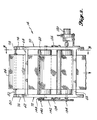
- the impregnator 14 includes a pair of box frames 60 and 62 on each side, joined by upper forward cross member 64, lower forward cross member 66, and lower rearward cross member 68.
- Side panels 70 and 72 are mounted on the outsides of the box frames 60 and 62.
- the bearings for all of the rollers in the impregnator are mounted on the side panels 70 and 72.
- a pair of uprights 74 and 76 extend upwardly from the upper end of the box frames.
- the uprights carry a pair of upwardly opening cradles 78 and 80.
- a roll 84 of fiberglass woven or unwoven fabric, is supported on a rod 82, which in turn rests in the cradles 80 and 78.
- a strip 86 of the fabric extends downwardly from the forward side of the roll 84 into a pair of nip rolls 90 and 92.
- the nip rolls are mounted in appropriate bearings on the side panels 70 and 72 at a location toward the upper rearward portion of the box frames 60 and 62.
- Nip rolls 90 and 92 serve to draw fabric from the roll 84 and control the descent of the fabric toward the first impregnator roll 94.
- the nip rolls 90 and 92 are mounted for rotation about horizontal axes that are parallel to each other.
- the surfaces of the nip rolls are composed of rubber or other high-friction material so that a good grip on the fabric is achieved. All of the remaining rolls in the apparatus are also mounted for rotation about horizontal axes that are parallel to each other.
- the first impregnator roll 94 is larger than the nip rolls and is mounted near the bottom rearward portion of the box frames.
- the fabric strip 86 extends around the rearward side of the roll 94 and up the forward side in a substantially vertical direction.
- the strip 86 then extends around a pressure roll 96, which is mounted above and slightly forwardly of the first impregnator roll 94, such that the fabric strip running between the roll 94 and 96 is substantially vertically oriented.
- the fabric strip then runs over the top of the pressure roll 96, around the front of the roll and back down toward the upper central portion of a second impregnator roll 98, which is mounted immediately forwardly of the first impregnator roll 94.
- An idler roll 100 is mounted above and slightly forwardly of the axis of the second impregnator roll 98.
- Fabric strip 86 extends downwardly from the pressure roll 96, around the rearward side of the idler roll 100 and between the idler roll and the second impregnator roll 98. Thereafter the fabric strip drops downwardly from the forward side of the impregnator roll 98 and is laid on a mold.
- Resin is supplied through a resin supply tube 110 extending through the right side panel 72 at a location above the impregnator roll 98, and between the first impregnator roll 94 and the idler roll 100.
- the resin is supplied to a pool 112 on the forward side of the fabric, which extends upwardly from the first impregnator roll 94 to the pressure roll 96.
- resin is supplied to only one side of the fabric so that air is not trapped within the fabric as is the case with prior art impregnators where resin is supplied from both sides of the fabric. Excess resin is supplied so that a layer of resin is still present on the forward side of the fabric strip 86 as it begins to engage the pressure roll 96.
- the shaft 120 of the idler roll 100 is mounted on a pair of horizontal arms 122 and 124.
- the arms extend forwardly from the shaft 120 and are mounted respectively to the side panels 72 and 70 via appropriate pivot pins.
- Conventional micrometer jackscrew adjusting mechanisms 124 and 126 are coupled between the central portions of the arms 122 and 124 and the side panels 70 and 72, allowing the arms to be selectively raised and lowered, thus raising and lowering the idler roll 100. In this manner, the distance of the surface of the idler roll 100 from the surface of the second impregnator roll 98 can be adjusted so that the exact amount of resin left in the fabric can be metered as desired.
- a pneumatically powered motor 130 is mounted on the left side of the impregnator.
- the motor powers a transmission 132, which in turn rotates the shaft 134 of the second impregnator roll 98.
- a sprocket 136 is attached to the opposite end of the shaft 134.
- a second sprocket 138 is affixed to the shaft 140 of the rearmost nip roll 90.
- An endless chain 142 couples the sprockets 136 and 138 so that the nip roll 90 is also driven.
- a pair of gears 144 are mounted respectively to the shafts 140 and 146 of the nip rolls 90 and 92 so that the nip rolls are simultaneously driven as well.
- the sprockets 136 and 138 and the gears 144 are sized such that the surface speeds of the nip rolls are matched to the surface speeds of the first impregnator roll 94.
- Rolls 94, 96 and 100 in the preferred embodiment are idlers, thus being driven by the fabric passing past the rolls.
- an optional seventh roll 150 is positioned above the first impregnator roll 94 and spaced away from the second impregnator roll 98.
- the seventh roll 150 presses the fabric against the first impregnator roll so that the fabric has a longer contact time with the puddle of resin between the first and second impregnator rolls.
- the fabric then extends upwardly from the seventh roll 150 to the pressure roll 96 and thence, as in the prior embodiments, to the idler 100 and second impregnator roll 98.
- roll 150 can be finned to allow more resin to remain on the inside of the strip 86 as it traverses toward the pressure roll 96.
- a pair of pinch rolls 152 and 154 are positioned below the pressure roll 96 and above the idler 100 and second impregnator roll 98. Fabric leaving the pressure roll traverses between the pinch rolls 152 and 154 and thence to the idler roll 100.
- an additional resin input port 156 can be provided above pinch roll 152 so that a pool of resin 158 is formed between the fabric and the inside pinch roll 152, which is positioned between the fabric going toward and leaving the pressure roll 96. Excess resin can drip over the inside of the inside pinch roll 152 and down into the original resin pool 112.
- inside pinch roll 152 can be finned so that additional resin is allowed to accumulate on the inside surface of the fabric as it extends down toward idler roll 100.
- FIGURE 8 illustrates a modification of the eight-roll system shown in FIGURE 7.
- a ninth roll 162 is positioned between the pinch rolls 152 and 154 and the idler roll 100.
- the ninth roll 162 is positioned on the inside of the fabric, that is, between the fabric extending from the impregnator rolls 94 and 98 toward the pressure roll 96 and the fabric leaving the pinch rolls 152 and 154 and extending toward the idler roll 100.
- the ninth roll 162 is offset outwardly so that the fabric traverses approximately 160° around ninth roll 162.
- the ninth roll causes additional flexure of the fiber and opens up the interstices between the fibers to cause better penetration of the resin into a heavy fabric or fabric laminate. If desired, the seventh, eighth, and ninth rolls can be driven to assure that they will turn as the fabric traverses them.
Landscapes
- Engineering & Computer Science (AREA)
- Mechanical Engineering (AREA)
- Reinforced Plastic Materials (AREA)
- Treatment Of Fiber Materials (AREA)
Applications Claiming Priority (2)
| Application Number | Priority Date | Filing Date | Title |
|---|---|---|---|
| US07/485,441 US5149372A (en) | 1990-02-27 | 1990-02-27 | Multiple roll impregnator |
| US485441 | 1990-02-27 |
Publications (2)
| Publication Number | Publication Date |
|---|---|
| EP0444823A2 true EP0444823A2 (de) | 1991-09-04 |
| EP0444823A3 EP0444823A3 (en) | 1992-03-25 |
Family
ID=23928182
Family Applications (1)
| Application Number | Title | Priority Date | Filing Date |
|---|---|---|---|
| EP19910301391 Ceased EP0444823A3 (en) | 1990-02-27 | 1991-02-21 | Multiple roll impregnator |
Country Status (4)
| Country | Link |
|---|---|
| US (1) | US5149372A (de) |
| EP (1) | EP0444823A3 (de) |
| JP (1) | JPH04214457A (de) |
| CA (1) | CA2036923A1 (de) |
Families Citing this family (9)
| Publication number | Priority date | Publication date | Assignee | Title |
|---|---|---|---|---|
| JP3664256B2 (ja) * | 1994-03-18 | 2005-06-22 | ザ、プロクター、エンド、ギャンブル、カンパニー | 個別化されたポリカルボン酸橋かけ結合セルロース繊維を製造する方法 |
| JP4712251B2 (ja) * | 2000-09-22 | 2011-06-29 | 帝人株式会社 | 両面同時塗工方法 |
| US20110048621A1 (en) * | 2007-07-03 | 2011-03-03 | Pekurovsky Mikhail L | Method of forming composite optical film |
| JP5493717B2 (ja) | 2009-10-30 | 2014-05-14 | 大日本印刷株式会社 | 画像処理装置、画像処理方法、および、画像処理用プログラム |
| JP5569042B2 (ja) | 2010-03-02 | 2014-08-13 | 株式会社リコー | 画像処理装置、撮像装置及び画像処理方法 |
| JP5966603B2 (ja) | 2011-06-28 | 2016-08-10 | 大日本印刷株式会社 | 画像処理装置、画像処理方法、画像処理用プログラム、および、記録媒体 |
| EP2756944B1 (de) * | 2011-09-14 | 2016-03-16 | Toyota Jidosha Kabushiki Kaisha | Herstellungsverfahren für eine faserverstärkte harzfolie und herstellungsvorrichtung dafür |
| US9475081B1 (en) * | 2014-09-23 | 2016-10-25 | Michael A. Ellis | Liquid application system for a flexible web |
| US11400479B1 (en) * | 2020-04-03 | 2022-08-02 | Michael A. Ellis | Adhesive applicator control system |
Family Cites Families (19)
| Publication number | Priority date | Publication date | Assignee | Title |
|---|---|---|---|---|
| DE28136C (de) * | H. SCHMIDT in Torgau | Einrichtung zur Benutzung von Beschneidmaschinen als Druck- und Vergoldepressen | ||
| US2009631A (en) * | 1932-05-28 | 1935-07-30 | Champion Coated Paper Company | Apparatus for coating paper |
| US2015531A (en) * | 1932-07-25 | 1935-09-24 | Champion Paper & Fibre Co | Roll coating machine |
| US2089524A (en) * | 1935-09-16 | 1937-08-10 | Marathon Paper Mills Co | Machine for and method of making coated sheet material |
| US2257113A (en) * | 1939-02-02 | 1941-09-30 | K C M Company | Coating apparatus |
| DE885777C (de) * | 1941-03-13 | 1953-08-06 | Reinz Dichtungs G M B H | Verfahren zur Herstellung von Flachdichtungen |
| US2511625A (en) * | 1946-04-30 | 1950-06-13 | Dungler Julien | Reservoir forming roller device for cloth dyeing and like machines |
| US2603077A (en) * | 1946-05-20 | 1952-07-15 | Dungler Julien | Machine for dyeing fabrics |
| US2623377A (en) * | 1948-01-15 | 1952-12-30 | Dungler Julien | Liquid-tight device for pairs of rollers forming a trough-shaped reservoir |
| US2618575A (en) * | 1948-10-22 | 1952-11-18 | British Cellophane Ltd | Production of moistureproof sheet wrapping material |
| US2961336A (en) * | 1955-06-17 | 1960-11-22 | Nat Steel Corp | Method of hot coating strip materials with paints or enamels |
| US3234041A (en) * | 1960-01-29 | 1966-02-08 | Owens Corning Fiberglass Corp | Method of applying binder to porous fibrous glass mats |
| NL261211A (de) * | 1960-04-22 | |||
| NL269645A (de) * | 1960-09-27 | |||
| DE1460188A1 (de) * | 1964-08-27 | 1970-01-15 | Artos Meier Windhorst Kg | Verfahren und Vorrichtung zum Impraegnieren von bahnfoermigen Guetern,insbesondere Textilbahnen |
| US3958432A (en) * | 1974-02-25 | 1976-05-25 | Aronoff Edward Israel | Apparatus for treating tubular fabrics |
| US3972209A (en) * | 1974-11-18 | 1976-08-03 | Serkov Arkadij T | Apparatus for washing yarn during movement thereof |
| US4193762A (en) * | 1978-05-01 | 1980-03-18 | United Merchants And Manufacturers, Inc. | Textile treatment process |
| SE413742B (sv) * | 1978-09-22 | 1980-06-23 | Billeruds Ab | Forfarande och anordning for att belegga en materialbana med en komposition |
-
1990
- 1990-02-27 US US07/485,441 patent/US5149372A/en not_active Expired - Fee Related
-
1991
- 1991-02-21 EP EP19910301391 patent/EP0444823A3/en not_active Ceased
- 1991-02-26 CA CA002036923A patent/CA2036923A1/en not_active Abandoned
- 1991-02-27 JP JP3032538A patent/JPH04214457A/ja active Pending
Also Published As
| Publication number | Publication date |
|---|---|
| JPH04214457A (ja) | 1992-08-05 |
| EP0444823A3 (en) | 1992-03-25 |
| CA2036923A1 (en) | 1991-08-28 |
| US5149372A (en) | 1992-09-22 |
Similar Documents
| Publication | Publication Date | Title |
|---|---|---|
| US5149372A (en) | Multiple roll impregnator | |
| DE2430514A1 (de) | Vorrichtung zur verbindung von bandmaterial, insbesondere zur verbindung von einer bearbeitungsmaschine zuzustellendem bandmaterial | |
| DE872440T1 (de) | Abwickelsystem mit Zentralantrieb | |
| DE994056T1 (de) | Abwickelsystem mit Zentralantrieb | |
| FR2537616A1 (fr) | Dispositif pour fabriquer des feutres sans fin aiguilletes pour machines a papier | |
| CN110697478A (zh) | 一种生产胶帆布用的卷布装置及方法 | |
| CN219490516U (zh) | 一种具有捋平功能的无纺布裁切装置 | |
| CN216889223U (zh) | 一种能自动纠偏的单向布条带放卷设备 | |
| DE3507667C2 (de) | ||
| CN206814078U (zh) | 一种铺网机 | |
| CN218453267U (zh) | 一种二合一基布加筋设备以及胎基布生产机构 | |
| DE19704332A1 (de) | Vorrichtung zum Bearbeiten von mindestens zwei Materialbahnen aus Papier oder Kunststoffolie | |
| CN218945455U (zh) | 纤维毡浸喷胶一体化设备 | |
| CN222064840U (zh) | 一种交叉式铺网机 | |
| CN209832602U (zh) | 铝板高速覆膜生产线 | |
| US3064308A (en) | Continuous production of profiled plastic sheets | |
| CN216189551U (zh) | 一种用于kt板生产系统的胶膜上料装置 | |
| CN221479000U (zh) | 用于黏胶基预氧毡生产的预氧机双层上料装置 | |
| DE4015864A1 (de) | Verfahren und vorrichtung zur herstellung von armierten gummibahnen als halbzeug fuer die produktion von reifen | |
| CN215710484U (zh) | 一种卷对卷软性电路板自动卷料装置 | |
| CN223478335U (zh) | 一种具有定位功能的无纺布覆膜装置 | |
| GB2036824A (en) | Cloth-laying machines | |
| JPS59153753A (ja) | シ−ト接続用スプライサ− | |
| CN215518158U (zh) | 浸胶机的双渗透系统 | |
| CN223045196U (zh) | 一种造纸毛毯底网用升降导料系统 |
Legal Events
| Date | Code | Title | Description |
|---|---|---|---|
| PUAI | Public reference made under article 153(3) epc to a published international application that has entered the european phase |
Free format text: ORIGINAL CODE: 0009012 |
|
| AK | Designated contracting states |
Kind code of ref document: A2 Designated state(s): BE DE FR GB IT LU NL |
|
| PUAL | Search report despatched |
Free format text: ORIGINAL CODE: 0009013 |
|
| AK | Designated contracting states |
Kind code of ref document: A3 Designated state(s): BE DE FR GB IT LU NL |
|
| 17P | Request for examination filed |
Effective date: 19920910 |
|
| 17Q | First examination report despatched |
Effective date: 19931206 |
|
| STAA | Information on the status of an ep patent application or granted ep patent |
Free format text: STATUS: THE APPLICATION HAS BEEN REFUSED |
|
| 18R | Application refused |
Effective date: 19941031 |