EP0444570B1 - Kühlsystem - Google Patents
Kühlsystem Download PDFInfo
- Publication number
- EP0444570B1 EP0444570B1 EP91102729A EP91102729A EP0444570B1 EP 0444570 B1 EP0444570 B1 EP 0444570B1 EP 91102729 A EP91102729 A EP 91102729A EP 91102729 A EP91102729 A EP 91102729A EP 0444570 B1 EP0444570 B1 EP 0444570B1
- Authority
- EP
- European Patent Office
- Prior art keywords
- electronic device
- temperature
- signal
- cooling system
- airtight box
- Prior art date
- Legal status (The legal status is an assumption and is not a legal conclusion. Google has not performed a legal analysis and makes no representation as to the accuracy of the status listed.)
- Expired - Lifetime
Links
Images


Classifications
-
- G—PHYSICS
- G06—COMPUTING OR CALCULATING; COUNTING
- G06F—ELECTRIC DIGITAL DATA PROCESSING
- G06F1/00—Details not covered by groups G06F3/00 - G06F13/00 and G06F21/00
- G06F1/16—Constructional details or arrangements
- G06F1/20—Cooling means
- G06F1/206—Cooling means comprising thermal management
-
- G—PHYSICS
- G06—COMPUTING OR CALCULATING; COUNTING
- G06F—ELECTRIC DIGITAL DATA PROCESSING
- G06F2200/00—Indexing scheme relating to G06F1/04 - G06F1/32
- G06F2200/20—Indexing scheme relating to G06F1/20
- G06F2200/201—Cooling arrangements using cooling fluid
Definitions
- the present invention generally relates to cooling systems, and more particularly to a cooling system which is designed so that an electronic device and a cooling module are accommodated within an airtight box and the electronic device is cooled by operating a coolant supplying unit.
- the electronic devices consume large power in order to realize high-speed operations and the electronic devices are equipped with a high density.
- the electronic devices are cooled by a cooling system. It is desirable that the cooling system cools the electronic devices to a relatively low temperature so as to fully bring out the performances of the electronic devices.
- a coolant such as liquid nitrogen and liquid helium is used to cool the high-speed elements.
- FIG.1 shows an example of a conventional cooling system.
- the cooling system includes an airtight box 3, a coolant supply unit 4, a unit 8 or 9, and a heater unit 15.
- An electronic device 1 is equipped with semiconductor elements, and a cooling module 2 cools the semiconductor elements of the electronic device.
- the electronic device 1 and the cooling module 2 are accommodated within the airtight box 3 which is made of a heat insulating material.
- the unit 8 absorbs the moisture within a chamber 3A inside the airtight box 3 to prevent dew condensation.
- the unit 9 replaces the air or predetermined gas inside the chamber 3A by a predetermined gas to prevent dew condensation when the temperature of the coolant is extremely low.
- One of the units 8 and 9 is provided depending on the needs.
- the heater unit 15 is used to raise the temperature within the chamber 3A if needed.
- a door 3B is provided on the airtight box 3, and the maintenance or removal of the electronic device 1 and/or the cooling module 2 can be made by opening the door 3B.
- the coolant supply unit 4 supplies a low temperature coolant 5 to the cooling module 2 within the airtight box 3 via a pipe 21 which is covered by a heat insulating material.
- the coolant 5 is then returned from the cooling module 2 to the coolant supply unit 4 via a pipe 21.
- the coolant 5 is recirculated between the coolant supply unit 4 and the cooling module 2.
- liquid helium, liquid nitrogen, fluon, fluorocarbon or the like may be used as the coolant 5.
- the coolant supply unit 4 includes a refrigerator 4B which refrigerates the coolant 5 via a heat exchanger 4A, and a pump 4C for forcibly pumping out the coolant 5 towards the airtight box 3.
- the pump 4C is driven to recirculate the coolant 5 with respect to the cooling module 2.
- the unit 8 absorbs the moisture within the chamber 3A or the unit 9 replaces the air within the chamber 3A by a predetermined gas when starting to cool the electronic device 1, and the heater unit 15 raises the temperature within the chamber 3A to a temperature approximately equal to that outside the chamber 3A when stopping to cool the electronic device 1 so as to attend to the maintenance of the electronic device 1 via the door 3B.
- the heater unit 15 raises the temperature within the chamber 3A to a temperature approximately equal to that outside the chamber 3A when stopping to cool the electronic device 1 so as to attend to the maintenance of the electronic device 1 via the door 3B.
- the coolant supply unit 4 may be operated when the humidity absorption is still insufficient. Similarly, when preventing the dew condensation by driving the unit 9, the coolant supply unit 4 may be operated when the replacement of air by the predetermined gas is not yet completed.
- the temperature of the cooled electronic device 1 may greatly differ from the temperature outside the chamber 3A. When the door 3B is opened in such cases, there is a problem in that the dew condensation in liquid or solid form occurs, thereby causing corrosion which deteriorates the performance of the electronic device 1.
- the dew condensation in the form of liquid or solid cannot be prevented unless the cooling operation is started depending on the operating states of the unit 8 or 9 and the electronic device 1 and unless the maintenance of the electronic device 1 is attended to depending on the operating state of the electronic device 1.
- the conventional cooling system also suffers from problems in that the system construction is complex due to the piping and sealing required in connection with the unit 8 or 9 and the heater unit 15 which must be connected to the airtight box 3.
- FR A1 2 580 060 discloses a similar cooling system to that of JP A 13 18 295 and also mentions using multiple switchable heat exchangers to regulate the cooling.
- the heating unit 15 heats the electronic device 1
- the heating is made via air or predetermined gas.
- a fan must be provided to circulate the heated air or the predetermined gas within the chamber 3A, thereby making the system construction more complex.
- the heating is made via air or predetermined gas, there are problems in that the heating of the electronic device 1 is inefficient and time consuming.
- Another and more specific object of the present invention is to provide a cooling system comprising an airtight box which accommodates a cooling module and an electronic device which is cooled by the cooling module and has a door which is opened when attending to maintenance of parts within the airtight box, a dew condensation preventing unit for absorbing humidity within the airtight box and/or replacing air or gas within the airtight box when operated, a coolant supply unit for recirculating a coolant between the coolant supply unit and the cooling module, and a controller for operating the coolant supply unit and the dew condensation preventing unit in response to a first instruction signal which instructs a cooling operation, and for heating the electronic device in response to a second instruction signal which instructs the maintenance of the parts within the airtight box, where only one of the first and second instruction signals exists at one time.
- the controller includes a circuit part responsive to the second instruction signal for supplying an operating signal to the electronic device to operate the electronic device for a predetermined time, so that the electronic device rises to a predetermined temperature due to heat generated by the electronic device itself.
- no complex mechanism is required to heat the electronic device when opening the door of the airtight box because the electronic device is heated by the heat generated by itself.
- no mechanism is required to circulate the air inside the airtight box in order to effectively heat the electronic device, and the heating efficiency is improved compared to the conventional cooling system. Further, the heating time is minimized because the electronic device is directly heated and not indirectly via air.
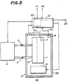
- FIG.2 generally shows a first embodiment of a cooling system according to the present invention.
- those parts which are the same as those corresponding parts in FIG.1 are designated by the same reference numerals, and a description thereof will be omitted.
- the cooling system shown in FIG.2 includes the airtight box 3, the coolant supply unit 4, a controller 10, and a temperature sensor 20.
- the electronic device 1, the cooling module 2, the unit 8, an absolute humidity sensor 6, and a temperature sensor 7 are provided within the chamber 3A.
- the absolute humidity sensor 6 detects the absolute humidity within the chamber 3A.
- the temperature sensor 7 detects the temperature of the electronic device 1.
- the temperature sensor 20 detects the ambient temperature outside the chamber 3A.
- the coolant supply unit 4 circulates the coolant 5 between the coolant supply unit 4 and the cooling module 2.
- unit 9 may be provided externally to the airtight box 3 in place of or in addition to the unit 8, similarly as shown for the conventional cooling system shown in FIG.1.
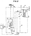
- FIG.3 shows an embodiment of the controller 10 together with a part of the electronic device 1.
- the controller 10 includes a first control part 100 and a second control part 101.
- the first control part 100 includes a dew condensation judging circuit 10A for which judges whether or not the dew condensation will occur based on an output signal Td of the absolute humidity sensor 6, and an AND gate G1 for obtaining an AND of a cooling instruction F1 and an output signal S1 of the dew condensation judging circuit 10A and for outputting a signal S2.
- the cooling instruction F1 is also supplied to the unit 8.
- the signal S2 is supplied to the coolant supply unit 4.
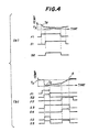
- FIG.4(a) shows the relationship of the signal Td, the cooling instruction F1, the output signal S1 of the dew condensation judging circuit 10A, and the output signal S2 of the AND gate G1.
- the dew condensation judging circuit 10A judges that the dew condensation will occur when the absolute humidity is greater than a predetermined value T3, and in this case, the dew condensation judging circuit 10A outputs a low-level signal S1.
- the signal S1 changes to a high level.
- the high level of the signal S1 is maintained until the absolute humidity next rises to the predetermined value T3.
- the unit 4 and the electronic device 1 are operated during a high-level period of the signal S2.
- the second control part 101 includes a temperature judging circuit 13, an AND gate G21, and an OR gate G22.
- the temperature judging circuit 13 judges whether or not the temperature of the electronic device 1 has reached a predetermined temperature based on the output signal Ta of the temperature sensor 7 and an output signal To of the temperature sensor 20.
- the predetermined temperature is the ambient temperature detected by the temperature sensor 20.
- the temperature judging circuit 13 may be designed to calculate the predetermined temperature based on the signal To.
- a removal instruction F2 is supplied to the AND gate G21 which receives an output signal S3 of the temperature judging circuit 13.
- the gate G22 obtains an OR of the signal S2 and an output signal S4 of the AND gate G21 and outputs a signal S5 which is supplied to the electronic device 1.
- the cooling instruction F1 instructs the cooling operation, while the removal instruction F2 instructs the maintenance of the parts within the airtight box 3. For this reason, only one of the cooling instruction F1 and the removal instruction F2 exists at one time, that is, the instructions F1 and F2 cannot assume the high level at the same time.
- FIG.4(b) shows the relationship of the signal Ta, the cooling instruction F1, the signal S2, the removal instruction F2, and the signals S3, S4, S2 and S5.
- the temperature judging circuit 13 outputs a high-level signal S3 during a time in which the temperature detected by the temperature sensor 7 is lower than the temperature detected by the temperature sensor 20.
- the signal S2 is output in response to the high-level cooling instruction F1 and the electronic device 1 and the coolant supply unit 4 are operated in response to the high-level signal S2. Then, when the cooling instruction F1 changes to the low level to indicate the stop of the cooling operation, the electronic device 1 and the coolant supply unit 4 stop operating in response to the low-level signal S2.
- the high-level removal instruction F2 is output thereafter to instruct the removal of the electronic device 1 from the chamber 3A
- the AND gate G21 outputs the high-level signal S4 and the OR gate G22 outputs the high-level signal S5 although the cooling instruction F1 has the low level.
- the operation of the electronic device 1 is resumed in response to the high-level signal S5 and the electronic device 1 operates until the temperature (Ta) of the electronic device 1 reaches the predetermined temperature (To).
- the temperature judging circuit 13 outputs the low-level signal S3 from a time A when the temperature (Ta) of the electronic device 1 reaches the predetermined temperature (To). As a result, the signal S5 changes to the low level, thereby stopping the operation of the electronic device 1.
- the electronic device 1 when there is a need to open the door 3B in order to attend to the maintenance of the electronic device 1 and/or the cooling module 2 in this embodiment, the electronic device 1 is operated to raise the temperature of the electronic device 1 by the heat generated thereby until the temperature of the electronic device 1 reaches such a temperature that no dew condensation will occur when the door 3B is opened. No heating unit and associated parts are required to raise the temperature of the electronic device 1.
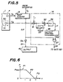
- FIG.5 shows an essential part of the second embodiment, and in FIG.5, those parts which are the same as those corresponding parts in FIG.3 are designated by the same reference numerals, and a description thereof will be omitted.
- a temperature sensor 111 is provided to detect the temperature of a semiconductor element 110 of the electronic device 1.
- An output signal Te of the temperature sensor 111 is supplied to an element temperature control circuit 14.
- the temperature judging circuit 14 outputs a signal S17 based on the output signal Ta of the temperature sensor 7 and the output signal To of the temperature sensor 20.
- the signal S17 is inverted by an inverter 54, and an output signal S11 of the inverter 54 is supplied to the output circuit 40.
- the element temperature control circuit 14 includes adders 31 and 32, an integrator 33, a multiplier 34, an output control circuit 36 and an AND circuit 37.
- the adder 31 adds the output signal Te of the temperature sensor 111 to a minus of a predetermined temperature T1. In other words, the predetermined temperature T1 is subtracted from the temperature indicated by the signal Te.
- An output signal of the adder 31 is supplied directly to the adder 32 on one hand, and is supplied to the adder 32 via the integrator 33 on the other.
- the integrator 33 obtains [1/T] ⁇ dt, where T denotes the integration time and ⁇ dt indicates an integration of the output of the adder 31 with respect to time.
- An output signal of the adder 32 is multiplied by a proportional gain K in the multiplier 34, and an output signal (variable) x of the multiplier 34 is supplied to the output control circuit 36.
- An output signal S12 of the output control circuit 36 is supplied to the AND circuit 37 which receives the output signal S17 of the temperature judging circuit 13.
- the output signal S3 of the AND circuit 37 is supplied to the AND gate G21 of the second control part 101 shown in FIG.3.
- the signal S12 is a pulse signal, and a time ratio P with which the signal S12 takes the high level is shown in FIG.6.
- the output control circuit 36 outputs the signal S12 such that the signal S12 has the pulse form at a portion P1 on the negative side of x and at a portion P2 shown in FIG.6, and has a low level ("0") at a portion P3 shown in FIG.6.
- a maximum value Pmax of the ratio P is restricted within a range from "0" to "1".
- Control constants such as T, K and Pmax are determined based on the electronic device 1 and the structure and material used for the cooling module 2. According to this embodiment, it is possible to efficiently heat the semiconductor element 110 without excessively heating the semiconductor element 110, even when the thermal transfer from the semiconductor element 110 to the surrounding is relatively poor.
- the output circuit 40 may be selected from any notifying means such as an indicator, a display, and an alarm.
- the output circuit 40 is an indicator, the indicator is turned ON or OFF in response to the high-level signal S11 to indicate that the door 3B of the airtight box 3 may be opened.
- the output circuit 40 may be an automatic locking mechanism which normally locks the door 3B but automatically opens the lock when the high-level signal S11 is received from the second control part 101.
- FIG.7 shows an essential part of the third embodiment, and in FIG.7, those parts which are the same as those corresponding parts in FIG.3 are designated by the same reference numerals, and a description thereof will be omitted.
- a timer 51 measures a time tm it takes to raise the temperature (Ta) of the electronic device 1 from the time when the removal instruction F2 is received, in a state where a switch 53 is connected to a contact 53 1 .
- the time tm is set in a timer 52 so that the electronic device 1 is operated for the fixed time tm the next time the removal instruction F2 is received.
- the switch 53 is switched and connected to a terminal 53 2 .
- the output signal S3 of the switch 53 is supplied to the AND gate G21, and the AND gate G21 outputs the signal S4 based on the signal S3 and the removal instruction F2.
- FIG.8 shows the relationship of the removal instruction F2 and the signal S3 which is obtained from the timer 52 via the terminal 53 2 and the signal 54.
- the signal S3 has the high level for the time tm which is set in the timer 52 and used in response to the second and subsequent removal instructions F2.
- a part surrounded by a dotted line in FIG.7 may be omitted after the time tm is set in the timer 52.
- the controller 10 of one airtight box 3 when a plurality of identical airtight boxes 3 exist and the electronic devices 1 accommodated therein are also the same, it is sufficient to provide the part surrounded by the dotted line in FIG.7 for the controller 10 of one airtight box 3, and the controllers 10 of the other airtight boxes 3 simply need to have the time tm set in the timer 32.
- the operating time of the electronic device 1 to the fixed time tm which is known from experience, it becomes possible to simplify the construction of the cooling system in that the temperature sensors 7 and 20, the temperature judging circuit 13 and the timer 51 may be omitted.
- timers 51 and 52 and the switch 53 are illustrated as being a part of the second control part 101 in FIG.7, the timers 51 and 52 and the switch 53 may of course be a part of the first control part 100.
Landscapes
- Engineering & Computer Science (AREA)
- Theoretical Computer Science (AREA)
- Human Computer Interaction (AREA)
- Physics & Mathematics (AREA)
- General Engineering & Computer Science (AREA)
- General Physics & Mathematics (AREA)
- Cooling Or The Like Of Electrical Apparatus (AREA)
- Cooling Or The Like Of Semiconductors Or Solid State Devices (AREA)
Claims (13)
- Kühlsystem mit einer luftdichten Box (3), die ein Kühlmodul (2) und eine elektronische Vorrichtung (1) enthält, die durch das Kühlmodul gekühlt wird, welche luftdichte Box eine Tür (3B) hat, die geöffnet wird, wenn Teile innerhalb der luftdichten Box gewartet werden; einer Taukondensationsverhinderungseinheit (8, 9) zum Absorbieren von Feuchtigkeit innerhalb der luftdichten Box und/oder Ersetzen von Luft oder Gas innerhalb der luftdichten Box, wenn sie betrieben wird; und einer Kühlmittelzuführeinheit (4), um ein Kühlmittel (5) zwischen der Kühlmittelzuführeinheit und dem Kühlmodul rezirkulieren zu lassen, dadurch gekennzeichnet, daß vorgesehen ist: ein Controllermittel (10) zum Betreiben der Kühlmittelzuführeinheit (4) und der Taukondensationsverhinderungseinheit (8, 9) als Reaktion auf ein erstes Instruktionssignal (F1, S2), welches eine Kühloperation anweist, und zum Erhitzen der elektronischen Vorrichtung (1) als Reaktion auf ein zweites Instruktionssignal (F2), welches die Wartung der Teile innerhalb der luftdichten Box anweist, wobei nur eines der ersten und zweiten Instruktionssignale auf einmal vorhanden ist; und daß das Controllermittel (10) ein Schaltungsmittel (101) enthält, das auf das zweite Instruktionssignal (F2) reagiert, zum Zuführen eines Operationssignals (S5) zu der elektronischen Vorrichtung (1), um die elektronische Vorrichtung eine vorbestimmte Zeit lang zu betreiben, so daß die elektronische Vorrichtung auf Grund der Wärme, die durch die elektronische Vorrichtung selbst erzeugt wird, eine vorbestimmte Temperatur erreicht.
- Kühlsystem nach Anspruch 1, dadurch gekennzeichnet, daß ferner ein erster Temperatursensor (7) vorgesehen ist, zum Detektieren einer Temperatur der elektronischen Vorrichtung (1) und zum Ausgeben eines ersten Detektionssignals (Ta), und das Schaltungsmittel (101) des Controllermittels (10) das Operationssignal (S5) als Reaktion auf das erste Detektionssignal (Ta) der elektronischen Vorrichtung (1) zuführt, um die elektronische Vorrichtung zu betreiben, bis die Temperatur der elektronischen Vorrichtung auf eine vorbestimmte Temperatur (To) ansteigt, wobei die vorbestimmte Zeit eine Variable ist.
- Kühlsystem nach Anspruch 2, dadurch gekennzeichnet, daß das Schaltungsmittel (101) des Controllermittels (10) die elektronische Vorrichtung (1) als Reaktion auf das zweite Instruktionssignal (F2) betreibt, nachdem die Kühlmittelzuführeinheit (4) stoppt.
- Kühlsystem nach Anspruch 2 oder 3, dadurch gekennzeichnet, daß ferner ein zweiter Temperatursensor (20) vorgesehen ist, zum Detektieren einer Umgebungstemperatur außerhalb der luftdichten Box (3) und zum Ausgeben eines zweiten Detektionssignals (To), und die vorbestimmte Temperatur von dem zweiten Detektionssignal abhängt.
- Kühlsystem nach Anspruch 2 oder 3, dadurch gekennzeichnet, daß ferner ein zweiter Temperatursensor (20) vorgesehen ist, zum Detektieren einer Umgebungstemperatur außerhalb der luftdichten Box (3) und zum Ausgeben eines zweiten Detektionssignals (To), und die vorbestimmte Temperatur die Umgebungstemperatur ist, die durch das zweite Detektionssignal angegeben wird.
- Kühlsystem nach irgendeinem der Ansprüche 2 bis 5, dadurch gekennzeichnet, daß ferner ein Absolutfeuchtigkeitssensor (6) vorgesehen ist, zum Detektieren einer absoluten Feuchtigkeit innerhalb der luftdichten Box (3) und zum Ausgeben eines Absolutfeuchtigkeitssignals (Td), und das Controllermittel (10) ein Beurteilungsmittel (10A) enthält, zum Beurteilen, auf der Basis des Absolutfeuchtigkeitssignals, ob eine Taukondensation innerhalb der luftdichten Box auftreten wird oder nicht, und ein Mittel (G1) zum Zuführen des ersten Instruktionssignals (S2) zu dem Schaltungsmittel (101) nur dann, wenn das Beurteilungsmittel beurteilt, daß die Taukondensation nicht auftreten wird.
- Kühlsystem nach irgendeinem der Ansprüche 2 bis 6, dadurch gekennzeichnet, daß ferner ein Meldemittel (40) vorgesehen ist, zum Melden, als Reaktion auf ein Steuersignal (S11), ob die Tür (3B) der luftdichten Box (3) geöffnet werden kann oder nicht, und das Controllermittel (10) ein Mittel (35) enthält, zum Ausgeben des Steuersignals (S11), wenn die Temperatur der elektronischen Vorrichtung (1) größer als die vorbestimmte Temperatur (To) oder ihr gleich wird, auf der Basis des ersten Detektionssignals (Ta).
- Kühlsystem nach irgendeinem der Ansprüche 2 bis 6, dadurch gekennzeichnet, daß ferner ein automatisches Verriegelungsmittel (40) vorgesehen ist, zum normalen Verriegeln der Tür (3B) der luftdichten Box (3) in einem verriegelten Zustand und zum automatischen Entriegeln der Tür als Reaktion auf ein Steuersignal (S11), und das Controllermittel (10) ein Mittel (35) enthält, zum Ausgeben des Steuersignals (S11), wenn die Temperatur der elektronischen Vorrichtung (1) größer als die vorbestimmte Temperatur (To) oder ihr gleich wird, auf der Basis des ersten Detektionssignals (Ta).
- Kühlsystem nach Anspruch 1, dadurch gekennzeichnet, daß das Controllermittel (10) ein Zeitgebermittel (52, 53) enthält, zum Zuführen des zweiten Instruktionssignals (F2) zu dem Schaltungsmittel (101) während der vorbestimmten Zeit (Tm), wobei die vorbestimmte Zeit feststehend ist.
- Kühlsystem nach Anspruch 9, dadurch gekennzeichnet, daß ferner ein Meßmittel (51) vorgesehen ist, zum Messen einer Zeit (tm), die ab einer Zeit, wenn das zweite Instruktionssignal (F2) empfangen wird, bis zu einer Zeit, wenn die Temperatur der elektronischen Vorrichtung (1) die vorbestimmte Temperatur (To) erreicht, benötigt wird, und zum Setzen der gemessenen Zeit (tm) in dem Zeitgebermittel (52, 53) als vorbestimmte Zeit.
- Kühlsystem nach irgendeinem der Ansprüche 1 bis 10, dadurch gekennzeichnet, daß die Taukondensationsverhinderungseinheit (8, 9) eine Absorptionseinheit (8) enthält, zum Absorbieren der Feuchtigkeit innerhalb der luftdichten Box (3), wenn sie betrieben wird.
- Kühlsystem nach Anspruch 11, dadurch gekennzeichnet, daß die Absorptionseinheit (8) innerhalb der luftdichten Box (3) untergebracht ist.
- Kühlsystem nach Anspruch 1, dadurch gekennzeichnet, daß ferner ein erster Temperatursensor (7) vorgesehen ist, zum Detektieren einer Temperatur der elektronischen Vorrichtung (1) und zum Ausgeben eines ersten Detektionssignals (Ta), und ein zweiter Temperatursensor (111) zum Detektieren einer Temperatur eines Halbleiterelementes (110) der elektronischen Vorrichtung und zum Ausgeben eines zweiten Detektionssignals (Te), und das Schaltungsmittel (101) des Controllermittels (10) das Operationssignal (S5) der elektronischen Vorrichtung als Reaktion auf die ersten und zweiten Detektionssignale zuführt, um die elektronische Vorrichtung zu betreiben, bis die Temperatur der elektronischen Vorrichtung auf die vorbestimmte Temperatur (To) ansteigt, die eine Variable ist, und die Temperatur des Halbleiterelementes eine gewisse Temperatur (T1) erreicht.
Applications Claiming Priority (2)
| Application Number | Priority Date | Filing Date | Title |
|---|---|---|---|
| JP2049839A JP2910127B2 (ja) | 1990-03-01 | 1990-03-01 | 冷却装置 |
| JP49839/90 | 1990-03-01 |
Publications (3)
| Publication Number | Publication Date |
|---|---|
| EP0444570A2 EP0444570A2 (de) | 1991-09-04 |
| EP0444570A3 EP0444570A3 (en) | 1993-06-30 |
| EP0444570B1 true EP0444570B1 (de) | 1999-02-03 |
Family
ID=12842249
Family Applications (1)
| Application Number | Title | Priority Date | Filing Date |
|---|---|---|---|
| EP91102729A Expired - Lifetime EP0444570B1 (de) | 1990-03-01 | 1991-02-25 | Kühlsystem |
Country Status (6)
| Country | Link |
|---|---|
| US (1) | US5136856A (de) |
| EP (1) | EP0444570B1 (de) |
| JP (1) | JP2910127B2 (de) |
| AU (1) | AU625025B2 (de) |
| CA (1) | CA2037138C (de) |
| DE (1) | DE69130838T2 (de) |
Cited By (1)
| Publication number | Priority date | Publication date | Assignee | Title |
|---|---|---|---|---|
| US9095075B2 (en) | 2012-11-27 | 2015-07-28 | Hamilton Sundstrand Corporation | Enclosure for electronic components with enhanced cooling |
Families Citing this family (19)
| Publication number | Priority date | Publication date | Assignee | Title |
|---|---|---|---|---|
| IT1251318B (it) * | 1991-09-13 | 1995-05-08 | Ente Naz Energia Elettrica | Apparecchiatura per controllare lo stato di contaminazione di isolatori elettrici |
| DE4241927C2 (de) * | 1992-12-11 | 1994-09-22 | Max Planck Gesellschaft | Zur Anordnung in einem Vakuumgefäß geeignete selbsttragende isolierte Elektrodenanordnung, insbesondere Antennenspule für einen Hochfrequenz-Plasmagenerator |
| US5473508A (en) * | 1994-05-31 | 1995-12-05 | At&T Global Information Solutions Company | Focused CPU air cooling system including high efficiency heat exchanger |
| JP3232908B2 (ja) * | 1994-09-20 | 2001-11-26 | 株式会社日立製作所 | 電子装置 |
| KR19980019402A (ko) * | 1998-03-16 | 1998-06-05 | 천기완 | 피.씨의 씨.피.유 냉각장치(cpu cooling device of pc) |
| JP3315649B2 (ja) * | 1998-08-11 | 2002-08-19 | 富士通株式会社 | 電子機器 |
| US6105875A (en) * | 1998-09-08 | 2000-08-22 | Lucent Technologies, Inc. | Direct air cooling of outdoor electronic cabinets |
| JP3470612B2 (ja) * | 1998-09-18 | 2003-11-25 | 株式会社日立製作所 | 電子機器 |
| JP2001077570A (ja) | 1999-09-06 | 2001-03-23 | Fujitsu Ltd | ロータ型除湿機およびロータ型除湿機の始動方法ならびに電子機器への取付け構造 |
| US6246581B1 (en) * | 1999-10-12 | 2001-06-12 | International Business Machines Corporation | Heated PCB interconnect for cooled IC chip modules |
| US20030035984A1 (en) | 2001-08-15 | 2003-02-20 | Colborn Jeffrey A. | Metal fuel cell system for providing backup power to one or more loads |
| KR20030020193A (ko) * | 2001-09-03 | 2003-03-08 | 이원재 | Cpu 냉각장치 |
| JP3879492B2 (ja) * | 2001-11-16 | 2007-02-14 | 株式会社日立製作所 | 制御装置の故障診断方法 |
| US7886983B2 (en) * | 2007-07-10 | 2011-02-15 | Liebert Corporation | Condensation prevention system and methods of use |
| JP2012175086A (ja) * | 2011-02-24 | 2012-09-10 | Fujitsu Ltd | 結露検知装置、電子機器冷却システム、及び結露検出方法 |
| US10582647B2 (en) * | 2014-02-19 | 2020-03-03 | Tetra Laval Holdings & Finance S.A. | Power supply unit |
| US20150243428A1 (en) * | 2014-02-21 | 2015-08-27 | Varentec, Inc. | Methods and systems of field upgradeable transformers |
| JP6285404B2 (ja) | 2015-12-04 | 2018-02-28 | ファナック株式会社 | 結露防止機能を有するレーザ装置 |
| TWI855719B (zh) * | 2023-06-06 | 2024-09-11 | 技嘉科技股份有限公司 | 溫度調節模組以及溫度調節方法 |
Family Cites Families (11)
| Publication number | Priority date | Publication date | Assignee | Title |
|---|---|---|---|---|
| US3417575A (en) * | 1967-04-10 | 1968-12-24 | Barber Colman Co | Method of and means for cooling semiconductor devices |
| JPS5899205A (ja) * | 1981-12-09 | 1983-06-13 | 株式会社日立製作所 | 密閉型制御盤の冷却装置 |
| JPS59119426A (ja) * | 1982-12-25 | 1984-07-10 | Fujitsu Ltd | 電子回路の起動方式 |
| JPS616916U (ja) * | 1984-06-20 | 1986-01-16 | 富士通テン株式会社 | 光学ヘツド |
| US4546619A (en) * | 1984-06-25 | 1985-10-15 | Rohner Thomas G | Mechanical cooler for electronics |
| FR2580060B1 (de) * | 1985-04-05 | 1989-06-09 | Nec Corp | |
| JPS6267618A (ja) * | 1985-09-20 | 1987-03-27 | Fujitsu Ltd | 電子装置の起動方法 |
| JPH0682941B2 (ja) * | 1987-10-22 | 1994-10-19 | 富士通株式会社 | 冷却液供給装置 |
| JPH01318295A (ja) * | 1988-06-20 | 1989-12-22 | Fujitsu Ltd | 電子機器の冷却装置 |
| FR2641662B1 (fr) * | 1988-12-27 | 1991-03-08 | Bull Sa | Armoire de machine de traitement de signaux refroidie par ventilation |
| EP0379211A3 (de) * | 1989-01-19 | 1990-10-10 | Nec Corporation | Kühlvorrichtung |
-
1990
- 1990-03-01 JP JP2049839A patent/JP2910127B2/ja not_active Expired - Fee Related
-
1991
- 1991-02-25 DE DE69130838T patent/DE69130838T2/de not_active Expired - Fee Related
- 1991-02-25 US US07/659,658 patent/US5136856A/en not_active Expired - Lifetime
- 1991-02-25 EP EP91102729A patent/EP0444570B1/de not_active Expired - Lifetime
- 1991-02-26 CA CA002037138A patent/CA2037138C/en not_active Expired - Fee Related
- 1991-02-27 AU AU71952/91A patent/AU625025B2/en not_active Ceased
Cited By (1)
| Publication number | Priority date | Publication date | Assignee | Title |
|---|---|---|---|---|
| US9095075B2 (en) | 2012-11-27 | 2015-07-28 | Hamilton Sundstrand Corporation | Enclosure for electronic components with enhanced cooling |
Also Published As
| Publication number | Publication date |
|---|---|
| DE69130838T2 (de) | 1999-06-24 |
| CA2037138C (en) | 1993-12-14 |
| JPH03252199A (ja) | 1991-11-11 |
| DE69130838D1 (de) | 1999-03-18 |
| AU7195291A (en) | 1991-09-05 |
| CA2037138A1 (en) | 1991-09-02 |
| US5136856A (en) | 1992-08-11 |
| EP0444570A3 (en) | 1993-06-30 |
| AU625025B2 (en) | 1992-06-25 |
| EP0444570A2 (de) | 1991-09-04 |
| JP2910127B2 (ja) | 1999-06-23 |
Similar Documents
| Publication | Publication Date | Title |
|---|---|---|
| US5136856A (en) | Cooling system | |
| US5860594A (en) | Method and apparatus for changing operational modes of a transport refrigeration system | |
| US6931872B2 (en) | Operation control device for cooling apparatus | |
| JPH06119083A (ja) | 電子機器の冷却装置 | |
| KR19980015709A (ko) | 냉장고의 고내온도 제어방법 | |
| JPH10332249A (ja) | 冷蔵庫 | |
| JPH07121242A (ja) | 電子機器の冷却装置及びその冷却方法 | |
| JPH02143054A (ja) | 保冷庫の圧縮機制御方法 | |
| JP2894817B2 (ja) | 電子機器用冷却装置 | |
| JPH01318295A (ja) | 電子機器の冷却装置 | |
| JPH09199648A (ja) | 水冷式インバータ装置の凍結防止方法 | |
| JPS613969A (ja) | 冷却貯蔵庫の冷却装置 | |
| JP2706365B2 (ja) | 陸上輸送用冷凍装置 | |
| KR0131282B1 (ko) | 냉장고의 압축기용 냉각 팬모터의 제어장치 | |
| JP4155647B2 (ja) | 冷却貯蔵庫 | |
| JP3020781B2 (ja) | 冷却装置 | |
| JPH04313672A (ja) | 冷凍装置 | |
| JP2851194B2 (ja) | 冷蔵庫の運転装置 | |
| KR100187201B1 (ko) | 냉장고의 운전방법 | |
| JPH0571846A (ja) | 冷凍冷蔵庫 | |
| JPH06281314A (ja) | 冷蔵庫 | |
| JPH01236699A (ja) | 電子機器の冷却装置 | |
| JP2924390B2 (ja) | 自動販売機の冷却加熱制御装置 | |
| KR19980015387A (ko) | 냉장고의 운전방법 | |
| JPH0863651A (ja) | 自動販売機の制御装置 |
Legal Events
| Date | Code | Title | Description |
|---|---|---|---|
| PUAI | Public reference made under article 153(3) epc to a published international application that has entered the european phase |
Free format text: ORIGINAL CODE: 0009012 |
|
| AK | Designated contracting states |
Kind code of ref document: A2 Designated state(s): DE FR GB |
|
| PUAL | Search report despatched |
Free format text: ORIGINAL CODE: 0009013 |
|
| AK | Designated contracting states |
Kind code of ref document: A3 Designated state(s): DE FR GB |
|
| 17P | Request for examination filed |
Effective date: 19931220 |
|
| 17Q | First examination report despatched |
Effective date: 19970609 |
|
| GRAG | Despatch of communication of intention to grant |
Free format text: ORIGINAL CODE: EPIDOS AGRA |
|
| GRAG | Despatch of communication of intention to grant |
Free format text: ORIGINAL CODE: EPIDOS AGRA |
|
| GRAG | Despatch of communication of intention to grant |
Free format text: ORIGINAL CODE: EPIDOS AGRA |
|
| GRAH | Despatch of communication of intention to grant a patent |
Free format text: ORIGINAL CODE: EPIDOS IGRA |
|
| GRAH | Despatch of communication of intention to grant a patent |
Free format text: ORIGINAL CODE: EPIDOS IGRA |
|
| GRAA | (expected) grant |
Free format text: ORIGINAL CODE: 0009210 |
|
| AK | Designated contracting states |
Kind code of ref document: B1 Designated state(s): DE FR GB |
|
| REF | Corresponds to: |
Ref document number: 69130838 Country of ref document: DE Date of ref document: 19990318 |
|
| ET | Fr: translation filed | ||
| PLBE | No opposition filed within time limit |
Free format text: ORIGINAL CODE: 0009261 |
|
| STAA | Information on the status of an ep patent application or granted ep patent |
Free format text: STATUS: NO OPPOSITION FILED WITHIN TIME LIMIT |
|
| 26N | No opposition filed | ||
| PGFP | Annual fee paid to national office [announced via postgrant information from national office to epo] |
Ref country code: FR Payment date: 20010213 Year of fee payment: 11 |
|
| PGFP | Annual fee paid to national office [announced via postgrant information from national office to epo] |
Ref country code: GB Payment date: 20010221 Year of fee payment: 11 Ref country code: DE Payment date: 20010221 Year of fee payment: 11 |
|
| REG | Reference to a national code |
Ref country code: GB Ref legal event code: IF02 |
|
| PG25 | Lapsed in a contracting state [announced via postgrant information from national office to epo] |
Ref country code: GB Free format text: LAPSE BECAUSE OF NON-PAYMENT OF DUE FEES Effective date: 20020225 |
|
| PG25 | Lapsed in a contracting state [announced via postgrant information from national office to epo] |
Ref country code: DE Free format text: LAPSE BECAUSE OF NON-PAYMENT OF DUE FEES Effective date: 20020903 |
|
| GBPC | Gb: european patent ceased through non-payment of renewal fee |
Effective date: 20020225 |
|
| PG25 | Lapsed in a contracting state [announced via postgrant information from national office to epo] |
Ref country code: FR Free format text: LAPSE BECAUSE OF NON-PAYMENT OF DUE FEES Effective date: 20021031 |
|
| REG | Reference to a national code |
Ref country code: FR Ref legal event code: ST |