EP0444018B1 - Moteur à combustion interne avec au moins deux soupapes d'admission par cylindre - Google Patents
Moteur à combustion interne avec au moins deux soupapes d'admission par cylindre Download PDFInfo
- Publication number
- EP0444018B1 EP0444018B1 EP91890033A EP91890033A EP0444018B1 EP 0444018 B1 EP0444018 B1 EP 0444018B1 EP 91890033 A EP91890033 A EP 91890033A EP 91890033 A EP91890033 A EP 91890033A EP 0444018 B1 EP0444018 B1 EP 0444018B1
- Authority
- EP
- European Patent Office
- Prior art keywords
- inlet
- internal combustion
- plane
- axis
- combustion engine
- Prior art date
- Legal status (The legal status is an assumption and is not a legal conclusion. Google has not performed a legal analysis and makes no representation as to the accuracy of the status listed.)
- Expired - Lifetime
Links
- 238000002485 combustion reaction Methods 0.000 title claims description 49
- 238000002347 injection Methods 0.000 claims description 20
- 239000007924 injection Substances 0.000 claims description 20
- 239000000203 mixture Substances 0.000 claims description 15
- 239000000446 fuel Substances 0.000 claims description 14
- 230000001154 acute effect Effects 0.000 claims description 8
- 230000015572 biosynthetic process Effects 0.000 claims 1
- 230000002452 interceptive effect Effects 0.000 claims 1
- 230000007935 neutral effect Effects 0.000 description 17
- 238000013517 stratification Methods 0.000 description 9
- 239000003344 environmental pollutant Substances 0.000 description 2
- 231100000719 pollutant Toxicity 0.000 description 2
- 230000001419 dependent effect Effects 0.000 description 1
- 230000002542 deteriorative effect Effects 0.000 description 1
- 230000000694 effects Effects 0.000 description 1
- 230000007246 mechanism Effects 0.000 description 1
- 238000011144 upstream manufacturing Methods 0.000 description 1
Images

Classifications
-
- F—MECHANICAL ENGINEERING; LIGHTING; HEATING; WEAPONS; BLASTING
- F02—COMBUSTION ENGINES; HOT-GAS OR COMBUSTION-PRODUCT ENGINE PLANTS
- F02M—SUPPLYING COMBUSTION ENGINES IN GENERAL WITH COMBUSTIBLE MIXTURES OR CONSTITUENTS THEREOF
- F02M35/00—Combustion-air cleaners, air intakes, intake silencers, or induction systems specially adapted for, or arranged on, internal-combustion engines
- F02M35/10—Air intakes; Induction systems
- F02M35/10209—Fluid connections to the air intake system; their arrangement of pipes, valves or the like
- F02M35/10216—Fuel injectors; Fuel pipes or rails; Fuel pumps or pressure regulators
-
- F—MECHANICAL ENGINEERING; LIGHTING; HEATING; WEAPONS; BLASTING
- F02—COMBUSTION ENGINES; HOT-GAS OR COMBUSTION-PRODUCT ENGINE PLANTS
- F02B—INTERNAL-COMBUSTION PISTON ENGINES; COMBUSTION ENGINES IN GENERAL
- F02B31/00—Modifying induction systems for imparting a rotation to the charge in the cylinder
- F02B31/08—Modifying induction systems for imparting a rotation to the charge in the cylinder having multiple air inlets
- F02B31/085—Modifying induction systems for imparting a rotation to the charge in the cylinder having multiple air inlets having two inlet valves
-
- F—MECHANICAL ENGINEERING; LIGHTING; HEATING; WEAPONS; BLASTING
- F02—COMBUSTION ENGINES; HOT-GAS OR COMBUSTION-PRODUCT ENGINE PLANTS
- F02D—CONTROLLING COMBUSTION ENGINES
- F02D13/00—Controlling the engine output power by varying inlet or exhaust valve operating characteristics, e.g. timing
- F02D13/02—Controlling the engine output power by varying inlet or exhaust valve operating characteristics, e.g. timing during engine operation
- F02D13/0223—Variable control of the intake valves only
- F02D13/0226—Variable control of the intake valves only changing valve lift or valve lift and timing
- F02D13/023—Variable control of the intake valves only changing valve lift or valve lift and timing the change of valve timing is caused by the change in valve lift, i.e. both valve lift and timing are functionally related
-
- F—MECHANICAL ENGINEERING; LIGHTING; HEATING; WEAPONS; BLASTING
- F02—COMBUSTION ENGINES; HOT-GAS OR COMBUSTION-PRODUCT ENGINE PLANTS
- F02D—CONTROLLING COMBUSTION ENGINES
- F02D41/00—Electrical control of supply of combustible mixture or its constituents
- F02D41/30—Controlling fuel injection
- F02D41/3094—Controlling fuel injection the fuel injection being effected by at least two different injectors, e.g. one in the intake manifold and one in the cylinder
-
- F—MECHANICAL ENGINEERING; LIGHTING; HEATING; WEAPONS; BLASTING
- F02—COMBUSTION ENGINES; HOT-GAS OR COMBUSTION-PRODUCT ENGINE PLANTS
- F02F—CYLINDERS, PISTONS OR CASINGS, FOR COMBUSTION ENGINES; ARRANGEMENTS OF SEALINGS IN COMBUSTION ENGINES
- F02F1/00—Cylinders; Cylinder heads
- F02F1/24—Cylinder heads
- F02F1/42—Shape or arrangement of intake or exhaust channels in cylinder heads
- F02F1/4214—Shape or arrangement of intake or exhaust channels in cylinder heads specially adapted for four or more valves per cylinder
-
- F—MECHANICAL ENGINEERING; LIGHTING; HEATING; WEAPONS; BLASTING
- F02—COMBUSTION ENGINES; HOT-GAS OR COMBUSTION-PRODUCT ENGINE PLANTS
- F02M—SUPPLYING COMBUSTION ENGINES IN GENERAL WITH COMBUSTIBLE MIXTURES OR CONSTITUENTS THEREOF
- F02M35/00—Combustion-air cleaners, air intakes, intake silencers, or induction systems specially adapted for, or arranged on, internal-combustion engines
- F02M35/10—Air intakes; Induction systems
- F02M35/1015—Air intakes; Induction systems characterised by the engine type
- F02M35/10177—Engines having multiple fuel injectors or carburettors per cylinder
-
- F—MECHANICAL ENGINEERING; LIGHTING; HEATING; WEAPONS; BLASTING
- F02—COMBUSTION ENGINES; HOT-GAS OR COMBUSTION-PRODUCT ENGINE PLANTS
- F02M—SUPPLYING COMBUSTION ENGINES IN GENERAL WITH COMBUSTIBLE MIXTURES OR CONSTITUENTS THEREOF
- F02M35/00—Combustion-air cleaners, air intakes, intake silencers, or induction systems specially adapted for, or arranged on, internal-combustion engines
- F02M35/10—Air intakes; Induction systems
- F02M35/104—Intake manifolds
- F02M35/108—Intake manifolds with primary and secondary intake passages
- F02M35/1085—Intake manifolds with primary and secondary intake passages the combustion chamber having multiple intake valves
-
- F—MECHANICAL ENGINEERING; LIGHTING; HEATING; WEAPONS; BLASTING
- F02—COMBUSTION ENGINES; HOT-GAS OR COMBUSTION-PRODUCT ENGINE PLANTS
- F02B—INTERNAL-COMBUSTION PISTON ENGINES; COMBUSTION ENGINES IN GENERAL
- F02B1/00—Engines characterised by fuel-air mixture compression
- F02B1/02—Engines characterised by fuel-air mixture compression with positive ignition
- F02B1/04—Engines characterised by fuel-air mixture compression with positive ignition with fuel-air mixture admission into cylinder
-
- F—MECHANICAL ENGINEERING; LIGHTING; HEATING; WEAPONS; BLASTING
- F02—COMBUSTION ENGINES; HOT-GAS OR COMBUSTION-PRODUCT ENGINE PLANTS
- F02B—INTERNAL-COMBUSTION PISTON ENGINES; COMBUSTION ENGINES IN GENERAL
- F02B31/00—Modifying induction systems for imparting a rotation to the charge in the cylinder
- F02B2031/006—Modifying induction systems for imparting a rotation to the charge in the cylinder having multiple air intake valves
-
- F—MECHANICAL ENGINEERING; LIGHTING; HEATING; WEAPONS; BLASTING
- F02—COMBUSTION ENGINES; HOT-GAS OR COMBUSTION-PRODUCT ENGINE PLANTS
- F02B—INTERNAL-COMBUSTION PISTON ENGINES; COMBUSTION ENGINES IN GENERAL
- F02B2275/00—Other engines, components or details, not provided for in other groups of this subclass
- F02B2275/48—Tumble motion in gas movement in cylinder
-
- F—MECHANICAL ENGINEERING; LIGHTING; HEATING; WEAPONS; BLASTING
- F02—COMBUSTION ENGINES; HOT-GAS OR COMBUSTION-PRODUCT ENGINE PLANTS
- F02D—CONTROLLING COMBUSTION ENGINES
- F02D13/00—Controlling the engine output power by varying inlet or exhaust valve operating characteristics, e.g. timing
- F02D13/02—Controlling the engine output power by varying inlet or exhaust valve operating characteristics, e.g. timing during engine operation
- F02D2013/0296—Changing the valve lift only
-
- F—MECHANICAL ENGINEERING; LIGHTING; HEATING; WEAPONS; BLASTING
- F02—COMBUSTION ENGINES; HOT-GAS OR COMBUSTION-PRODUCT ENGINE PLANTS
- F02F—CYLINDERS, PISTONS OR CASINGS, FOR COMBUSTION ENGINES; ARRANGEMENTS OF SEALINGS IN COMBUSTION ENGINES
- F02F1/00—Cylinders; Cylinder heads
- F02F1/02—Cylinders; Cylinder heads having cooling means
- F02F1/10—Cylinders; Cylinder heads having cooling means for liquid cooling
- F02F2001/104—Cylinders; Cylinder heads having cooling means for liquid cooling using an open deck, i.e. the water jacket is open at the block top face
-
- F—MECHANICAL ENGINEERING; LIGHTING; HEATING; WEAPONS; BLASTING
- F02—COMBUSTION ENGINES; HOT-GAS OR COMBUSTION-PRODUCT ENGINE PLANTS
- F02F—CYLINDERS, PISTONS OR CASINGS, FOR COMBUSTION ENGINES; ARRANGEMENTS OF SEALINGS IN COMBUSTION ENGINES
- F02F1/00—Cylinders; Cylinder heads
- F02F1/24—Cylinder heads
- F02F2001/244—Arrangement of valve stems in cylinder heads
- F02F2001/245—Arrangement of valve stems in cylinder heads the valve stems being orientated at an angle with the cylinder axis
-
- Y—GENERAL TAGGING OF NEW TECHNOLOGICAL DEVELOPMENTS; GENERAL TAGGING OF CROSS-SECTIONAL TECHNOLOGIES SPANNING OVER SEVERAL SECTIONS OF THE IPC; TECHNICAL SUBJECTS COVERED BY FORMER USPC CROSS-REFERENCE ART COLLECTIONS [XRACs] AND DIGESTS
- Y02—TECHNOLOGIES OR APPLICATIONS FOR MITIGATION OR ADAPTATION AGAINST CLIMATE CHANGE
- Y02T—CLIMATE CHANGE MITIGATION TECHNOLOGIES RELATED TO TRANSPORTATION
- Y02T10/00—Road transport of goods or passengers
- Y02T10/10—Internal combustion engine [ICE] based vehicles
- Y02T10/12—Improving ICE efficiencies
Definitions
- the invention relates to an internal combustion engine with at least two intake valves per engine cylinder, which in the closed state are the same distance from a plane normal to the cylinder axis, and a combustion chamber delimited by roof-shaped boundary surfaces in the cylinder head, the main flow direction of the intake valves into the combustion chamber sucked in partial flows with the plane determined by the engine cylinder axes of a row of cylinders, the plane of symmetry, each enclose an acute angle, the partial flows flowing through inlet openings into the combustion chamber, each lying on one side of a normal plane containing the cylinder axis at the plane of symmetry.
- the main inflow channels are closed and the inflow takes place via an additional channel that opens into one of the main inflow channels shortly before the inlet valve, see e.g. DE-OS 37 18 083.
- inlet ducts An asymmetrical design of the inlet ducts is also widely known, with one inlet duct being “helical”, “twisted” or with a “swivel end piece”.
- Such channels cause a pronounced inlet swirl, i.e. without being influenced by the second inlet channel. a rotational movement of the charge about an axis parallel to the cylinder axis.
- a high degree of charge movement can be realized by closing the straight intake duct in the partial load, high air throughputs, e.g. at full load or high engine speed, even when opening the straight duct, this spiral or helical duct design means significantly lower maximum air throughputs than would otherwise result from a comparable duct design.
- the twisted design of an intake duct at high full-load speeds causes the combustion process to be too rapid, which results in disadvantages with regard to combustion noise.
- EP-A2 0 321 313 it is known from EP-A2 0 321 313 to arrange three intake valves per engine cylinder symmetrically to a normal plane containing the cylinder axis on the previously defined plane of symmetry.
- the middle inlet duct lying in the normal plane has a different angle of inclination than the two outer inlet ducts.
- the invention has for its object to avoid these disadvantages of the known designs and in particular to achieve a strong swirl of the charge in the combustion chamber at part load without, however, hindering the charge inflow at full load due to poorer flow coefficients and thus deteriorating the performance of the engine.
- the angle of at least one partial flow on one side of a normal plane containing the cylinder axis on the plane of symmetry is 10-40 ° greater than the angle of at least one corresponding partial flow on the opposite side of the normal plane
- the angles of the partial flows to the plane of symmetry are determined by the shape of the inlet channels to the inlet valves, so that both a swirl movement about an axis parallel to the crankshaft and a swirl movement about an axis parallel to the cylinder axis are initiated such that a mutual obstruction of the partial flows is avoided.
- two inlet channels designed for good air flow behavior are provided in the invention, which bring about an increased degree of charge movement primarily through the special coordination of their entry angles into the combustion chamber.
- the axis of the inlet channel to the first inlet valve at least just before this inlet valve coincides with the axis of this inlet valve or is parallel thereto and the axis of the inlet channel to the second inlet valve, at least just before this second inlet valve, with the Axis of this inlet valve encloses an acute angle.
- the first inlet channel the so-called “neutral channel” opens into the combustion chamber at a comparatively acute angle to the plane of symmetry, so that there is a main inflow direction of the sucked-in mixture partial flow which forms only a small acute angle to the plane of symmetry.
- the channel design is chosen so that the entire inlet valve plate is acted upon as uniformly as possible by the inlet flow and thus there is a main inflow direction approximately in the direction of the inlet valve axis.
- the second channel the so-called “tangential channel” opens under a 10 - 40 ° larger one Angle to the plane of symmetry in the combustion chamber and is designed so that there is a main flow direction of the sucked mixture portion at the largest possible angle to the plane of symmetry. Due to the special design of the inlet channel, the part of the valve disk which is closer to the outlet valves is acted upon by the inlet flow.
- the flat inlet angle of the inlet duct into the combustion chamber and the additional asymmetrical deflection on the valve plate result in a very flat main inflow direction.
- the mass flowing in through the neutral channel at a small angle to the plane of symmetry has a substantially smaller pulse perpendicular to the axis of symmetry than the mass flowing in through the tangential channel.
- This turns both a swirl movement around the crankshaft parallel axis, as well as a swirl movement about an axis parallel to the cylinder axis.
- This increased charge movement leads, particularly under partial load conditions, to a faster combustion process, in particular to a significantly shortened ignition phase.
- the inlet channels can advantageously be guided completely separately, both in the cylinder head and in the intake manifold, up to a collecting tank common to several engine cylinders.
- a fuel injection valve can be arranged in each of the two inlet channels, and the distribution of the amount of fuel injected into each of these two injection valves can be varied depending on the operating conditions of the engine (engine load, engine speed).
- the inlet ducts can also be guided separately up to a collecting tank common to several engine cylinders, but a defined opening can be present in the vicinity of the inlet valves between the two intake ducts.
- the charge stratification takes place to such an extent that by maintaining the same injection quantities in the two inlet ducts, but throttling the air flow in the neutral duct, a comparatively rich mixture is drawn in through the neutral duct, but comparatively lean mixture is drawn in through the tangential duct.
- This throttling takes place both by closing the suction pipe leading to the neutral channel, if necessary while maintaining a defined leakage air and additionally by a cross flow from the tangential channel through the precisely defined opening between the two channels.
- this precisely defined opening additionally allows the fuel supply to both inlet ducts with only one injection valve, in that one injection valve per engine cylinder is arranged symmetrically to the two intake ducts in such a way that the two fuel jets of this injection valve are directed through the defined opening onto the inlet valve plate.
- stratification with a rich mixture near the spark plug and a lean mixture in zones near the wall can also be achieved by mixing directly in the combustion chamber, e.g. by high-pressure injection or fuel injection into the combustion chamber.
- the stratification can be maintained up to the ignition point and thus leads to faster and more stable combustion.
- a throttle element can be arranged in that inlet duct in the flow direction upstream of the injection valve (s) from which the partial flow forming a smaller angle with the plane of symmetry emerges and the intake air flow in this inlet duct is throttled depending on the engine operating state.
- the neutral channel is throttled, the straight channel (tangential channel) remains open under all operating conditions
- the throttling of the air mass flowing through the neutral channel can not only be carried out in the manner described above by a throttle body, but it is also possible within the scope of the invention that the throttling of the partial flow of the intake air, which forms the smaller angle with the plane of symmetry, by a from Engine operating state dependent change of the intake valve lift curve takes place.
- this change in the valve lift curve is preferably brought about by early closing of the inlet valve.
- the intake valve lift curve can also be influenced by other mechanisms known per se, e.g. also vary the maximum intake valve lift.
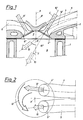
- the cylinder block is denoted by 1 and the cylinder head fastened thereon by 2.
- the roof-shaped combustion chamber 3 as well as the inlet channels 4 and 5 and the outlet channel 6 or the outlet channels 6.
- the associated intake and exhaust valves are 4 'and 6' and the associated cross-sections with 4 ⁇ and 5 ⁇ and 6 ⁇ .
- the inlet channel 5 opens out as a so-called neutral channel at a comparatively acute angle 7 to the plane of symmetry 8 determined by the engine cylinder axes 8 'of a row of cylinders in the combustion chamber 3 or in the space 9.
- the inlet channel 5 is designed so that a main flow direction of the sucked mixture Partial current at a small angle 7 to the plane of symmetry 8 results.
- the channel design is selected so that the entire intake valve plate is acted upon as uniformly as possible by the intake flow - compare FIG. 3 - and there is a main flow direction approximately in the direction of the intake valve axis 10 ', which is indicated by the dashed arrow 10.
- the inlet duct 5 is shown in broken lines in FIG. 1.
- the second inlet channel 4 the so-called tangential channel, opens at an angle 11 to the plane of symmetry 8 in the combustion chamber 3 or engine compartment 9, which angle is 10-40 ° larger than the angle 7.
- This angle 11 is designed so that a The main flow direction of the sucked-in mixture portion results at the largest possible angle to the plane of symmetry, which is shown by the fully extended arrow 12 in FIGS. 1 and 4.
- the two inlet channels 4 and 5 are on both sides of a normal plane 8 ⁇ on the plane of symmetry 8. It is essential for the invention that the angle of the partial flow 12 on one side of the normal plane 8 ⁇ by 10 to 40 ° is greater than the angle 7 of the partial flow 10 on the opposite side of the normal plane 8 ⁇ .
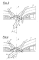
- the mass flowing in through the neutral channel 5 at a small angle 7 to the plane of symmetry 8 has a substantially smaller pulse perpendicular to it Plane of symmetry 8 as the mass flowing in through the tangential channel 4.
- This initiates both a swirl movement about an axis parallel to the crankshaft, and a swirl movement about an axis parallel to the cylinder axis 8 '.
- This increased charge movement leads, especially under partial load conditions, to a faster combustion process, in particular to a significantly shorter ignition phase.
- this charge movement can initiate a charge stratification introduced in the inlet channels with a different fuel / air mixture ratio in the combustion chamber in a form which favors the combustion process and can be maintained until ignition. This results in higher combustion stability, improved leanability and greater tolerance to main gas recirculation as well as the resulting improvements in fuel consumption and pollutant emissions.
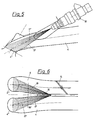
- the throttling in the neutral channel 5 by the throttle valve 14 takes place, if necessary, while maintaining a defined leakage air and additionally through a cross flow from the tangential channel through the precisely defined opening 15 be maintained at the time of ignition.
- FIGS. 7 and 8 differs from that according to FIGS. 5 and 6 in that the neutral channel 5 and the tangential channel 4 are guided completely separately from one another and each have an injection nozzle 18, the jets 19 and 20 of which have their center lines 19 'and 20' are directed against the middle of the valve inlet cross sections 5 ⁇ and 4 ⁇ . Any charge stratification can be achieved by varying the fuel quantities injected through the nozzles.
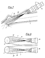
- This change in the valve lift curve can preferably be brought about by early closing of the intake valve, which e.g. can be effected by electrohydraulic control of an intermediate element between the inlet valve and the camshaft.
- FIG. 9 where the valve lift H is plotted over the crank angle KW.
- Another possibility is to vary the maximum intake valve lift H, as shown in FIG. 10.
Landscapes
- Engineering & Computer Science (AREA)
- Chemical & Material Sciences (AREA)
- Combustion & Propulsion (AREA)
- Mechanical Engineering (AREA)
- General Engineering & Computer Science (AREA)
- Combustion Methods Of Internal-Combustion Engines (AREA)
Claims (9)
- Moteur à combustion interne avec au moins deux soupapes d'admission pour chaque cylindre ; du moteur qui en position fermée sont éloignées à la même distance d'un plan se trouvant perpendiculaire à l'axe du cylindre (8′) et avec une chambre de combustion (5˝) limitée par des surfaces de délimitation en forme de toit dans la culasse (2), moteur dans lequel les directions d'écoulement principales des flux partiels (10, 12) aspirés par les soupapes d'admission (4′, 5′) dans la chambre de combustion (3) forment un angle aigu respectif avec le plan déterminé par les axes (8˝) d'une rangée de cylindres, le plan de symétrie (8), les flux partiels (10, 12) entrant à travers les orifices d'admission (4˝, 5˝) dans la chambre de combustion (3), qui se trouvent respectivement sur un côté d'un plan perpendiculaire (8˝) contenant l'axe du cylindre (8′) par rapport au plan de symétrie (8), moteur à combustion interne caractérisé en ce que l'angle (11) d'au moins un flux partiel (12) sur un côté d'un plan standard (8˝) contenant l'axe du cylindre (8′) est plus grand par rapport au plan de symétrie (8) de 10° à 40° que l'angle (7) d'au moins un flux partiel (10) correspondant par rapport au côté opposé du plan perpendiculaire (8˝), les angles (7, 11) des flux partiels (10, 12) par rapport , au plan de symétrie (8) étant déterminés par la forme des canaux d'admission (4, 5) allant aux soupapes d'admission (4′, 5′), de telle sorte que l'on initie aussi bien un mouvement de torsion autour d'un axe parallèle à l'arbre du vilebrequin qu'un mouvement de torsion (13) aussi autour d'une axe parallèle à l'axe du cylindre (8′), de telle manière que l'on évite une gêne réciproque des flux partiels.
- Moteur à combustion interne selon la revendication 1, caractérisé en ce que l'axe (10˝) du canal d'admission (5) allant à la premiere soupape d'admission (5′) coïncide du moins peu avant cette soupape d'admission avec l'axe (1, D′) de cette soupape d'admission (5′) ou est parallèle à celui-ci et que l'axe (12′) du canal d'admission (4) allant à la deuxième soupape d'admission (4′) , du moins peu avant cette deuxième soupape d'admission(4′) forme avec l'axe (10′) de cette soupape d'admission (4′) un angle aigu.
- Moteur à combustion interne selon la revendication 1 ou 2, caractérisé en ce que les canaux d'admission (4, 5) aussi bien dans la culasse (2) que dans la pipe d'admission aussi sont construits de façon complètement séparés jusqu'au réservoir collecteur commun à plusieurs cylindres du moteur.
- Moteur à combustion interne selon l'une des revendication 1 à 3 caractérisé en ce que dans chacun des deux canaux d'admission (4, 5) est disposée une soupape d'injection de carburant (18), la répartition des quantités de carburant respectivement injectées par ces deux soupapes d'injection (18) pouvant être modulée selon les conditions de fonctionnement du moteur (charge du moteur, vitesse de rotation)
- Moteur à combustion interne selon la revendication 1 ou 2, caractérisé en ce que les canaux d'admission (4, 5) sont construits de façon séparée jusqu'à un réservoir, collecteur commun à plusieurs cylindres du moteur, mais qu'il y a à proximité des soupapes d'admission (4′, 5′) un orifice défini (15) entre les deux canaux d'admission (4, 5).
- Moteur à combustion selon la revendication 5, caractérisé en ce qu'une soupape d'injection (18) pour chaque cylindre du moteur est disposée symétriquement par rapport aux deux canaux d'admission (4, 5) de telle façon que les pots de carburant (16, 17) de cette soupape d'injection (18) soient dirigés à travers l'orifice défini (15) sur les têtes des soupapes d'admission.
- Moteur à combustion interne selon l'une des revendications 1 a 3, caractérisé en ce que la formation du mélange se produit directement dans la chambre de combustion (3), par exemple par injection à haute pression ou par insufflation de carburant dans la chambre de combustion.
- Moteur à combustion interne selon l'une des revendications 1 à 7, caractérisé en ce qu'un organe d'étranglement (14) est disposé dans le sens de l'écoulement dans chaque signal d'admission (5) avant la (les) soupape(s) d'admission (18), à partir de laquelle soit le flux partiel formant un angle plus petit avec le plan de symétrie (8) et en ce qu'il se produit un étranglement du courant d'air aspiré dans le canal d'admission (5) en fonction de l'état de marche du moteur.
- Moteur à combustion interne selon la revendication 7, caractérisé en ce que l'étranglement du flux partiel (10) d'air aspiré, qui forme l'angle plus petit avec le plan de symétrie (8) résulte d'une variante de la courbe de soulèvement de la soupape d'admission (5′) qui dépend de l'état de marche du moteur.
Applications Claiming Priority (2)
| Application Number | Priority Date | Filing Date | Title |
|---|---|---|---|
| AT435/90 | 1990-02-23 | ||
| AT0043590A AT402535B (de) | 1990-02-23 | 1990-02-23 | Brennkraftmaschine mit zumindest zwei einlassventilen je motorzylinder |
Publications (2)
| Publication Number | Publication Date |
|---|---|
| EP0444018A1 EP0444018A1 (fr) | 1991-08-28 |
| EP0444018B1 true EP0444018B1 (fr) | 1994-08-10 |
Family
ID=3490536
Family Applications (1)
| Application Number | Title | Priority Date | Filing Date |
|---|---|---|---|
| EP91890033A Expired - Lifetime EP0444018B1 (fr) | 1990-02-23 | 1991-02-19 | Moteur à combustion interne avec au moins deux soupapes d'admission par cylindre |
Country Status (4)
| Country | Link |
|---|---|
| US (1) | US5138989A (fr) |
| EP (1) | EP0444018B1 (fr) |
| AT (1) | AT402535B (fr) |
| DE (1) | DE59102460D1 (fr) |
Families Citing this family (37)
| Publication number | Priority date | Publication date | Assignee | Title |
|---|---|---|---|---|
| KR950011323B1 (ko) * | 1991-05-14 | 1995-09-30 | 마쯔다 가부시기가이샤 | 엔진의 연소실 구조 |
| US5301641A (en) * | 1991-11-06 | 1994-04-12 | Honda Giken Kogyo Kabushiki Kaisha | Internal combustion engine |
| JP3003339B2 (ja) * | 1991-12-06 | 2000-01-24 | トヨタ自動車株式会社 | 燃料噴射式内燃機関の吸気装置 |
| FR2712028B1 (fr) * | 1993-11-04 | 1995-12-15 | Renault | Moteur à combustion interne à injection indirecte de carburant. |
| JPH07150945A (ja) * | 1993-11-26 | 1995-06-13 | Yamaha Motor Co Ltd | 4サイクルエンジンの燃焼室構造 |
| AT405672B (de) * | 1994-03-31 | 1999-10-25 | Avl Verbrennungskraft Messtech | Verfahren zur einbringung von kraftstoff in den brennraum einer brennkraftmaschine |
| EP0676533B1 (fr) * | 1994-04-09 | 1997-09-24 | Adam Opel Ag | Système de cannaux d'admission pour un moteur à combustion interne |
| US5551401A (en) * | 1994-05-31 | 1996-09-03 | Suzuki Motor Corporation | Air suction system for internal combustion engine |
| FR2727722A1 (fr) * | 1994-12-01 | 1996-06-07 | Magneti Marelli France | Jupe de dispersion de carburant, pour injecteur d'un moteur a injection |
| JPH08200023A (ja) * | 1995-01-24 | 1996-08-06 | Toyota Motor Corp | 内燃機関のシリンダヘッド構造 |
| IT1285853B1 (it) * | 1996-04-24 | 1998-06-24 | Fiat Ricerche | Motore a combustione interna con valvole ad azionamento variabile. |
| JPH108971A (ja) * | 1996-06-19 | 1998-01-13 | Yamaha Motor Co Ltd | 筒内燃料噴射式エンジン |
| AT2434U1 (de) * | 1997-10-21 | 1998-10-27 | Avl List Gmbh | Fremdgezündete brennkraftmaschine |
| AT2489U1 (de) * | 1997-11-20 | 1998-11-25 | Avl List Gmbh | Hubkolbenbrennkraftmaschine mit fremdzündung |
| JP3939864B2 (ja) * | 1998-08-27 | 2007-07-04 | ヤマハ発動機株式会社 | 筒内噴射式エンジン |
| AT3138U1 (de) * | 1998-11-16 | 1999-10-25 | Avl List Gmbh | Viertakt-brennkraftmaschine mit mindestens zwei einlassventilen pro zylinder |
| GB9920666D0 (en) * | 1999-09-01 | 1999-11-03 | Zalkin Anthony L | Improved internal combustion engine |
| AT4966U1 (de) * | 2000-03-14 | 2002-01-25 | Avl List Gmbh | Viertakt-brennkraftmaschine mit zumindest zwei einlassventilen |
| AT4788U1 (de) | 2000-06-28 | 2001-11-26 | Avl List Gmbh | Brennkraftmaschine |
| AT5137U1 (de) * | 2000-09-21 | 2002-03-25 | Avl List Gmbh | Viertakt-brennkraftmaschine mit mindestens zwei einlassventilen pro zylinder |
| EP1191211B1 (fr) | 2000-09-21 | 2004-08-11 | AVL List GmbH | Méthode de fonctionnement d'un moteur à combustion interne |
| AT5781U1 (de) * | 2001-04-19 | 2002-11-25 | Avl List Gmbh | Brennkraftmaschine mit mindestens einem einlassventil |
| AT5648U1 (de) | 2001-08-02 | 2002-09-25 | Avl List Gmbh | Brennkraftmaschine mit zumindest zwei einlassventilen pro zylinder |
| AT500408B8 (de) * | 2004-10-04 | 2007-02-15 | Avl List Gmbh | Brennkraftmaschine mit zumindest zwei einlasskanälen pro zylinder |
| JP2005307904A (ja) * | 2004-04-23 | 2005-11-04 | Denso Corp | 燃料噴射装置 |
| JP2006070860A (ja) * | 2004-09-06 | 2006-03-16 | Honda Motor Co Ltd | 内燃機関の吸気ポート構造 |
| FR2879666B1 (fr) * | 2004-12-21 | 2010-01-15 | Inst Francais Du Petrole | Procede de commande d'un moteur a combustion interne suralimente a allumage commande, notamment de type essence |
| US7565894B2 (en) * | 2005-09-12 | 2009-07-28 | Hitachi, Ltd. | Fuel injection apparatus for and method of internal combustion engine, and fuel injection valve |
| AT500926B1 (de) * | 2006-01-10 | 2007-12-15 | Avl List Gmbh | Brennkraftmaschine, insbesondere aufgeladene brennkraftmaschine |
| US7347178B2 (en) * | 2006-01-12 | 2008-03-25 | Ford Global Technologies, Llc | System and method for controlling auto-ignition |
| CN102207052B (zh) * | 2006-03-29 | 2013-02-06 | 株式会社电装 | 燃料喷射阀的安装构造及燃料喷射系统 |
| AT506469B1 (de) | 2009-03-26 | 2010-12-15 | Avl List Gmbh | Brennkraftmaschine |
| EP2418365B1 (fr) * | 2010-08-12 | 2012-07-18 | C.R.F. Società Consortile per Azioni | Chambre de combustion pour moteurs diesel dotée de soupapes de moteur inclinées |
| JP5541535B2 (ja) * | 2011-09-13 | 2014-07-09 | 日立オートモティブシステムズ株式会社 | 内燃機関の燃料噴射制御装置 |
| WO2013162527A1 (fr) * | 2012-04-25 | 2013-10-31 | International Engine Intellectual Property Company, Llc | Agencement de soupapes d'admission induisant un tourbillon |
| WO2015073380A1 (fr) * | 2013-11-12 | 2015-05-21 | Matthew Riley | Systèmes et procédés d'induction d'air forcée dans des moteurs à combustion interne |
| DE102017216996B3 (de) | 2017-09-26 | 2019-01-17 | Bayerische Motoren Werke Aktiengesellschaft | Verbrennungsmotor |
Citations (2)
| Publication number | Priority date | Publication date | Assignee | Title |
|---|---|---|---|---|
| JPS60108529A (ja) * | 1983-11-17 | 1985-06-14 | Mazda Motor Corp | エンジンの吸気装置 |
| DE3502699A1 (de) * | 1984-01-26 | 1985-08-14 | Mazda Motor Corp., Hiroshima | Ansaugvorrichtung fuer kolben-brennkraftmaschine |
Family Cites Families (12)
| Publication number | Priority date | Publication date | Assignee | Title |
|---|---|---|---|---|
| JPS5845571B2 (ja) * | 1978-01-12 | 1983-10-11 | 日産自動車株式会社 | 内燃機関の燃焼室 |
| GB2113759A (en) * | 1982-01-21 | 1983-08-10 | Ricardo Consulting Eng | Combustion chamber arrangements in ic engines |
| US4548175A (en) * | 1983-12-05 | 1985-10-22 | Toyota Jidosha Kabushiki Kaisha | Internal combustion engine with two intake valves |
| FR2584455B1 (fr) * | 1985-07-08 | 1989-07-28 | Peugeot | Culasse de moteur a combustion interne avec trois soupapes par cylindre |
| JPS62228622A (ja) * | 1986-03-31 | 1987-10-07 | Yamaha Motor Co Ltd | エンジンの吸気装置 |
| JPS62284919A (ja) * | 1986-06-04 | 1987-12-10 | Mazda Motor Corp | エンジンの燃焼室構造 |
| IT1223543B (it) * | 1987-12-18 | 1990-09-19 | Alfa Lancia Ind | Dispositivo di aspirazione per un motore a c.i. pluricilindrico |
| JPH0755330Y2 (ja) * | 1987-12-18 | 1995-12-20 | 三菱自動車工業株式会社 | 3個の吸気弁を備えた内燃エンジン |
| JPH0745817B2 (ja) * | 1988-02-12 | 1995-05-17 | 本田技研工業株式会社 | 直噴式多気筒ディーゼル機関 |
| JPH068604B2 (ja) * | 1988-05-23 | 1994-02-02 | 本田技研工業株式会社 | 内燃機関の弁作動状態切換装置 |
| JPH0733766B2 (ja) * | 1988-08-30 | 1995-04-12 | トヨタ自動車株式会社 | 内燃機関の燃焼室 |
| JPH02149769A (ja) * | 1988-11-30 | 1990-06-08 | Fuji Heavy Ind Ltd | 4バルブ式エンジン燃焼室の点火プラグ配列装置 |
-
1990
- 1990-02-23 AT AT0043590A patent/AT402535B/de not_active IP Right Cessation
-
1991
- 1991-02-19 EP EP91890033A patent/EP0444018B1/fr not_active Expired - Lifetime
- 1991-02-19 DE DE59102460T patent/DE59102460D1/de not_active Expired - Fee Related
- 1991-02-20 US US07/657,857 patent/US5138989A/en not_active Expired - Lifetime
Patent Citations (2)
| Publication number | Priority date | Publication date | Assignee | Title |
|---|---|---|---|---|
| JPS60108529A (ja) * | 1983-11-17 | 1985-06-14 | Mazda Motor Corp | エンジンの吸気装置 |
| DE3502699A1 (de) * | 1984-01-26 | 1985-08-14 | Mazda Motor Corp., Hiroshima | Ansaugvorrichtung fuer kolben-brennkraftmaschine |
Also Published As
| Publication number | Publication date |
|---|---|
| ATA43590A (de) | 1996-10-15 |
| EP0444018A1 (fr) | 1991-08-28 |
| US5138989A (en) | 1992-08-18 |
| AT402535B (de) | 1997-06-25 |
| DE59102460D1 (de) | 1994-09-15 |
Similar Documents
| Publication | Publication Date | Title |
|---|---|---|
| EP0444018B1 (fr) | Moteur à combustion interne avec au moins deux soupapes d'admission par cylindre | |
| DE69103000T2 (de) | Luftansauganlage für eine brennkraftmaschine. | |
| DE3444356C2 (fr) | ||
| DE69318326T2 (de) | Brennkraftmaschine mit geschichteter Ladung | |
| DE4439918C2 (de) | Vorrichtung zur Zufuhr eines Kraftstoff/Luft-Gemisches zu einer Brennkraftmaschine | |
| DE3600408C2 (fr) | ||
| DE2803533A1 (de) | Luftverdichtende, selbstzuendende brennkraftmaschine | |
| DE69519490T2 (de) | Brennkraftmaschine und Verfahren zur Luft-Kraftstoffgemischbildung dafür | |
| DE4439921C2 (de) | Einlaßsystem einer Brennkraftmaschine | |
| DE19622891C2 (de) | Abgasrückführungssystem | |
| EP0764773B1 (fr) | Moteur à combustion à quatre temps | |
| DE9319545U1 (de) | Fremdgezündeter Kolbenmotor mit richtungsänderbarer Einströmung des Kraftstoff-Luft-Gemisches | |
| EP0911502B1 (fr) | Moteur à combustion à allumage commandé | |
| DE10110986B4 (de) | Viertakt-Brennkraftmaschine mit zumindest zwei Einlassventilen | |
| DE3718083A1 (de) | Brennraum an einer kolben-brennkraftmaschine | |
| DE69606884T2 (de) | Schichtladungsbrennkraftmaschine | |
| DE69517938T2 (de) | Verfahren und Vorrichtung zur Abgasrückführung für eine 4-Takt Brennkraftmaschine mit Fremdzündung | |
| EP0676533B1 (fr) | Système de cannaux d'admission pour un moteur à combustion interne | |
| DE3903831C2 (fr) | ||
| DE3936263A1 (de) | Brennkraftmaschine | |
| DE3836550A1 (de) | Einlasskanalsystem fuer eine brennkraftmaschine mit zwei im zylinderkopf angeordneten einlassventilen pro zylinder | |
| DE4205237C2 (de) | Einlaßkanal in einem Zylinderkopf einer Brennkraftmaschine mit mindestens zwei Einlaßventilen pro Zylinder | |
| DE69221651T2 (de) | Einlasssystem für eine Brennkraftmaschine | |
| EP1134403B1 (fr) | Moteur à combustion avec recirculation de gaz d'échappement | |
| EP1290320B1 (fr) | Systeme et procede d'injection de carburant |
Legal Events
| Date | Code | Title | Description |
|---|---|---|---|
| PUAI | Public reference made under article 153(3) epc to a published international application that has entered the european phase |
Free format text: ORIGINAL CODE: 0009012 |
|
| AK | Designated contracting states |
Kind code of ref document: A1 Designated state(s): DE FR GB IT SE |
|
| GBC | Gb: translation of claims filed (gb section 78(7)/1977) | ||
| EL | Fr: translation of claims filed | ||
| 17P | Request for examination filed |
Effective date: 19911008 |
|
| 17Q | First examination report despatched |
Effective date: 19920416 |
|
| GRAA | (expected) grant |
Free format text: ORIGINAL CODE: 0009210 |
|
| AK | Designated contracting states |
Kind code of ref document: B1 Designated state(s): DE FR GB IT SE |
|
| REF | Corresponds to: |
Ref document number: 59102460 Country of ref document: DE Date of ref document: 19940915 |
|
| ET | Fr: translation filed | ||
| GBT | Gb: translation of ep patent filed (gb section 77(6)(a)/1977) |
Effective date: 19940901 |
|
| ITF | It: translation for a ep patent filed | ||
| EAL | Se: european patent in force in sweden |
Ref document number: 91890033.3 |
|
| PLBE | No opposition filed within time limit |
Free format text: ORIGINAL CODE: 0009261 |
|
| STAA | Information on the status of an ep patent application or granted ep patent |
Free format text: STATUS: NO OPPOSITION FILED WITHIN TIME LIMIT |
|
| 26N | No opposition filed | ||
| REG | Reference to a national code |
Ref country code: GB Ref legal event code: IF02 |
|
| PGFP | Annual fee paid to national office [announced via postgrant information from national office to epo] |
Ref country code: SE Payment date: 20020227 Year of fee payment: 12 |
|
| PG25 | Lapsed in a contracting state [announced via postgrant information from national office to epo] |
Ref country code: SE Free format text: LAPSE BECAUSE OF NON-PAYMENT OF DUE FEES Effective date: 20030220 |
|
| EUG | Se: european patent has lapsed | ||
| PGFP | Annual fee paid to national office [announced via postgrant information from national office to epo] |
Ref country code: GB Payment date: 20070214 Year of fee payment: 17 |
|
| PGFP | Annual fee paid to national office [announced via postgrant information from national office to epo] |
Ref country code: IT Payment date: 20070514 Year of fee payment: 17 |
|
| PGFP | Annual fee paid to national office [announced via postgrant information from national office to epo] |
Ref country code: FR Payment date: 20070226 Year of fee payment: 17 |
|
| PGFP | Annual fee paid to national office [announced via postgrant information from national office to epo] |
Ref country code: DE Payment date: 20080429 Year of fee payment: 18 |
|
| GBPC | Gb: european patent ceased through non-payment of renewal fee |
Effective date: 20080219 |
|
| REG | Reference to a national code |
Ref country code: FR Ref legal event code: ST Effective date: 20081031 |
|
| PG25 | Lapsed in a contracting state [announced via postgrant information from national office to epo] |
Ref country code: FR Free format text: LAPSE BECAUSE OF NON-PAYMENT OF DUE FEES Effective date: 20080229 |
|
| PG25 | Lapsed in a contracting state [announced via postgrant information from national office to epo] |
Ref country code: GB Free format text: LAPSE BECAUSE OF NON-PAYMENT OF DUE FEES Effective date: 20080219 |
|
| PG25 | Lapsed in a contracting state [announced via postgrant information from national office to epo] |
Ref country code: IT Free format text: LAPSE BECAUSE OF NON-PAYMENT OF DUE FEES Effective date: 20080219 |
|
| PG25 | Lapsed in a contracting state [announced via postgrant information from national office to epo] |
Ref country code: DE Free format text: LAPSE BECAUSE OF NON-PAYMENT OF DUE FEES Effective date: 20090901 |