EP0444018B1 - Internal combustion engine comprising at least two inlet valves per cylinder - Google Patents
Internal combustion engine comprising at least two inlet valves per cylinder Download PDFInfo
- Publication number
- EP0444018B1 EP0444018B1 EP91890033A EP91890033A EP0444018B1 EP 0444018 B1 EP0444018 B1 EP 0444018B1 EP 91890033 A EP91890033 A EP 91890033A EP 91890033 A EP91890033 A EP 91890033A EP 0444018 B1 EP0444018 B1 EP 0444018B1
- Authority
- EP
- European Patent Office
- Prior art keywords
- inlet
- internal combustion
- plane
- axis
- combustion engine
- Prior art date
- Legal status (The legal status is an assumption and is not a legal conclusion. Google has not performed a legal analysis and makes no representation as to the accuracy of the status listed.)
- Expired - Lifetime
Links
- 238000002485 combustion reaction Methods 0.000 title claims description 49
- 238000002347 injection Methods 0.000 claims description 20
- 239000007924 injection Substances 0.000 claims description 20
- 239000000203 mixture Substances 0.000 claims description 15
- 239000000446 fuel Substances 0.000 claims description 14
- 230000001154 acute effect Effects 0.000 claims description 8
- 230000015572 biosynthetic process Effects 0.000 claims 1
- 230000002452 interceptive effect Effects 0.000 claims 1
- 230000007935 neutral effect Effects 0.000 description 17
- 238000013517 stratification Methods 0.000 description 9
- 239000003344 environmental pollutant Substances 0.000 description 2
- 231100000719 pollutant Toxicity 0.000 description 2
- 230000001419 dependent effect Effects 0.000 description 1
- 230000002542 deteriorative effect Effects 0.000 description 1
- 230000000694 effects Effects 0.000 description 1
- 230000007246 mechanism Effects 0.000 description 1
- 238000011144 upstream manufacturing Methods 0.000 description 1
Images

Classifications
-
- F—MECHANICAL ENGINEERING; LIGHTING; HEATING; WEAPONS; BLASTING
- F02—COMBUSTION ENGINES; HOT-GAS OR COMBUSTION-PRODUCT ENGINE PLANTS
- F02M—SUPPLYING COMBUSTION ENGINES IN GENERAL WITH COMBUSTIBLE MIXTURES OR CONSTITUENTS THEREOF
- F02M35/00—Combustion-air cleaners, air intakes, intake silencers, or induction systems specially adapted for, or arranged on, internal-combustion engines
- F02M35/10—Air intakes; Induction systems
- F02M35/10209—Fluid connections to the air intake system; their arrangement of pipes, valves or the like
- F02M35/10216—Fuel injectors; Fuel pipes or rails; Fuel pumps or pressure regulators
-
- F—MECHANICAL ENGINEERING; LIGHTING; HEATING; WEAPONS; BLASTING
- F02—COMBUSTION ENGINES; HOT-GAS OR COMBUSTION-PRODUCT ENGINE PLANTS
- F02B—INTERNAL-COMBUSTION PISTON ENGINES; COMBUSTION ENGINES IN GENERAL
- F02B31/00—Modifying induction systems for imparting a rotation to the charge in the cylinder
- F02B31/04—Modifying induction systems for imparting a rotation to the charge in the cylinder by means within the induction channel, e.g. deflectors
- F02B31/06—Movable means, e.g. butterfly valves
- F02B31/08—Movable means, e.g. butterfly valves having multiple air inlets, i.e. having main and auxiliary intake passages
- F02B31/085—Movable means, e.g. butterfly valves having multiple air inlets, i.e. having main and auxiliary intake passages having two inlet valves
-
- F—MECHANICAL ENGINEERING; LIGHTING; HEATING; WEAPONS; BLASTING
- F02—COMBUSTION ENGINES; HOT-GAS OR COMBUSTION-PRODUCT ENGINE PLANTS
- F02D—CONTROLLING COMBUSTION ENGINES
- F02D13/00—Controlling the engine output power by varying inlet or exhaust valve operating characteristics, e.g. timing
- F02D13/02—Controlling the engine output power by varying inlet or exhaust valve operating characteristics, e.g. timing during engine operation
- F02D13/0223—Variable control of the intake valves only
- F02D13/0226—Variable control of the intake valves only changing valve lift or valve lift and timing
- F02D13/023—Variable control of the intake valves only changing valve lift or valve lift and timing the change of valve timing is caused by the change in valve lift, i.e. both valve lift and timing are functionally related
-
- F—MECHANICAL ENGINEERING; LIGHTING; HEATING; WEAPONS; BLASTING
- F02—COMBUSTION ENGINES; HOT-GAS OR COMBUSTION-PRODUCT ENGINE PLANTS
- F02D—CONTROLLING COMBUSTION ENGINES
- F02D41/00—Electrical control of supply of combustible mixture or its constituents
- F02D41/30—Controlling fuel injection
- F02D41/3094—Controlling fuel injection the fuel injection being effected by at least two different injectors, e.g. one in the intake manifold and one in the cylinder
-
- F—MECHANICAL ENGINEERING; LIGHTING; HEATING; WEAPONS; BLASTING
- F02—COMBUSTION ENGINES; HOT-GAS OR COMBUSTION-PRODUCT ENGINE PLANTS
- F02F—CYLINDERS, PISTONS OR CASINGS, FOR COMBUSTION ENGINES; ARRANGEMENTS OF SEALINGS IN COMBUSTION ENGINES
- F02F1/00—Cylinders; Cylinder heads
- F02F1/24—Cylinder heads
- F02F1/42—Shape or arrangement of intake or exhaust channels in cylinder heads
- F02F1/4214—Shape or arrangement of intake or exhaust channels in cylinder heads specially adapted for four or more valves per cylinder
-
- F—MECHANICAL ENGINEERING; LIGHTING; HEATING; WEAPONS; BLASTING
- F02—COMBUSTION ENGINES; HOT-GAS OR COMBUSTION-PRODUCT ENGINE PLANTS
- F02M—SUPPLYING COMBUSTION ENGINES IN GENERAL WITH COMBUSTIBLE MIXTURES OR CONSTITUENTS THEREOF
- F02M35/00—Combustion-air cleaners, air intakes, intake silencers, or induction systems specially adapted for, or arranged on, internal-combustion engines
- F02M35/10—Air intakes; Induction systems
- F02M35/1015—Air intakes; Induction systems characterised by the engine type
- F02M35/10177—Engines having multiple fuel injectors or carburettors per cylinder
-
- F—MECHANICAL ENGINEERING; LIGHTING; HEATING; WEAPONS; BLASTING
- F02—COMBUSTION ENGINES; HOT-GAS OR COMBUSTION-PRODUCT ENGINE PLANTS
- F02M—SUPPLYING COMBUSTION ENGINES IN GENERAL WITH COMBUSTIBLE MIXTURES OR CONSTITUENTS THEREOF
- F02M35/00—Combustion-air cleaners, air intakes, intake silencers, or induction systems specially adapted for, or arranged on, internal-combustion engines
- F02M35/10—Air intakes; Induction systems
- F02M35/104—Intake manifolds
- F02M35/108—Intake manifolds with primary and secondary intake passages
- F02M35/1085—Intake manifolds with primary and secondary intake passages the combustion chamber having multiple intake valves
-
- F—MECHANICAL ENGINEERING; LIGHTING; HEATING; WEAPONS; BLASTING
- F02—COMBUSTION ENGINES; HOT-GAS OR COMBUSTION-PRODUCT ENGINE PLANTS
- F02B—INTERNAL-COMBUSTION PISTON ENGINES; COMBUSTION ENGINES IN GENERAL
- F02B1/00—Engines characterised by fuel-air mixture compression
- F02B1/02—Engines characterised by fuel-air mixture compression with positive ignition
- F02B1/04—Engines characterised by fuel-air mixture compression with positive ignition with fuel-air mixture admission into cylinder
-
- F—MECHANICAL ENGINEERING; LIGHTING; HEATING; WEAPONS; BLASTING
- F02—COMBUSTION ENGINES; HOT-GAS OR COMBUSTION-PRODUCT ENGINE PLANTS
- F02B—INTERNAL-COMBUSTION PISTON ENGINES; COMBUSTION ENGINES IN GENERAL
- F02B31/00—Modifying induction systems for imparting a rotation to the charge in the cylinder
- F02B2031/006—Modifying induction systems for imparting a rotation to the charge in the cylinder having multiple air intake valves
-
- F—MECHANICAL ENGINEERING; LIGHTING; HEATING; WEAPONS; BLASTING
- F02—COMBUSTION ENGINES; HOT-GAS OR COMBUSTION-PRODUCT ENGINE PLANTS
- F02B—INTERNAL-COMBUSTION PISTON ENGINES; COMBUSTION ENGINES IN GENERAL
- F02B2275/00—Other engines, components or details, not provided for in other groups of this subclass
- F02B2275/48—Tumble motion in gas movement in cylinder
-
- F—MECHANICAL ENGINEERING; LIGHTING; HEATING; WEAPONS; BLASTING
- F02—COMBUSTION ENGINES; HOT-GAS OR COMBUSTION-PRODUCT ENGINE PLANTS
- F02D—CONTROLLING COMBUSTION ENGINES
- F02D13/00—Controlling the engine output power by varying inlet or exhaust valve operating characteristics, e.g. timing
- F02D13/02—Controlling the engine output power by varying inlet or exhaust valve operating characteristics, e.g. timing during engine operation
- F02D2013/0296—Changing the valve lift only
-
- F—MECHANICAL ENGINEERING; LIGHTING; HEATING; WEAPONS; BLASTING
- F02—COMBUSTION ENGINES; HOT-GAS OR COMBUSTION-PRODUCT ENGINE PLANTS
- F02F—CYLINDERS, PISTONS OR CASINGS, FOR COMBUSTION ENGINES; ARRANGEMENTS OF SEALINGS IN COMBUSTION ENGINES
- F02F1/00—Cylinders; Cylinder heads
- F02F1/02—Cylinders; Cylinder heads having cooling means
- F02F1/10—Cylinders; Cylinder heads having cooling means for liquid cooling
- F02F2001/104—Cylinders; Cylinder heads having cooling means for liquid cooling using an open deck, i.e. the water jacket is open at the block top face
-
- F—MECHANICAL ENGINEERING; LIGHTING; HEATING; WEAPONS; BLASTING
- F02—COMBUSTION ENGINES; HOT-GAS OR COMBUSTION-PRODUCT ENGINE PLANTS
- F02F—CYLINDERS, PISTONS OR CASINGS, FOR COMBUSTION ENGINES; ARRANGEMENTS OF SEALINGS IN COMBUSTION ENGINES
- F02F1/00—Cylinders; Cylinder heads
- F02F1/24—Cylinder heads
- F02F2001/244—Arrangement of valve stems in cylinder heads
- F02F2001/245—Arrangement of valve stems in cylinder heads the valve stems being orientated at an angle with the cylinder axis
-
- Y—GENERAL TAGGING OF NEW TECHNOLOGICAL DEVELOPMENTS; GENERAL TAGGING OF CROSS-SECTIONAL TECHNOLOGIES SPANNING OVER SEVERAL SECTIONS OF THE IPC; TECHNICAL SUBJECTS COVERED BY FORMER USPC CROSS-REFERENCE ART COLLECTIONS [XRACs] AND DIGESTS
- Y02—TECHNOLOGIES OR APPLICATIONS FOR MITIGATION OR ADAPTATION AGAINST CLIMATE CHANGE
- Y02T—CLIMATE CHANGE MITIGATION TECHNOLOGIES RELATED TO TRANSPORTATION
- Y02T10/00—Road transport of goods or passengers
- Y02T10/10—Internal combustion engine [ICE] based vehicles
- Y02T10/12—Improving ICE efficiencies
Definitions
- the invention relates to an internal combustion engine with at least two intake valves per engine cylinder, which in the closed state are the same distance from a plane normal to the cylinder axis, and a combustion chamber delimited by roof-shaped boundary surfaces in the cylinder head, the main flow direction of the intake valves into the combustion chamber sucked in partial flows with the plane determined by the engine cylinder axes of a row of cylinders, the plane of symmetry, each enclose an acute angle, the partial flows flowing through inlet openings into the combustion chamber, each lying on one side of a normal plane containing the cylinder axis at the plane of symmetry.
- the main inflow channels are closed and the inflow takes place via an additional channel that opens into one of the main inflow channels shortly before the inlet valve, see e.g. DE-OS 37 18 083.
- inlet ducts An asymmetrical design of the inlet ducts is also widely known, with one inlet duct being “helical”, “twisted” or with a “swivel end piece”.
- Such channels cause a pronounced inlet swirl, i.e. without being influenced by the second inlet channel. a rotational movement of the charge about an axis parallel to the cylinder axis.
- a high degree of charge movement can be realized by closing the straight intake duct in the partial load, high air throughputs, e.g. at full load or high engine speed, even when opening the straight duct, this spiral or helical duct design means significantly lower maximum air throughputs than would otherwise result from a comparable duct design.
- the twisted design of an intake duct at high full-load speeds causes the combustion process to be too rapid, which results in disadvantages with regard to combustion noise.
- EP-A2 0 321 313 it is known from EP-A2 0 321 313 to arrange three intake valves per engine cylinder symmetrically to a normal plane containing the cylinder axis on the previously defined plane of symmetry.
- the middle inlet duct lying in the normal plane has a different angle of inclination than the two outer inlet ducts.
- the invention has for its object to avoid these disadvantages of the known designs and in particular to achieve a strong swirl of the charge in the combustion chamber at part load without, however, hindering the charge inflow at full load due to poorer flow coefficients and thus deteriorating the performance of the engine.
- the angle of at least one partial flow on one side of a normal plane containing the cylinder axis on the plane of symmetry is 10-40 ° greater than the angle of at least one corresponding partial flow on the opposite side of the normal plane
- the angles of the partial flows to the plane of symmetry are determined by the shape of the inlet channels to the inlet valves, so that both a swirl movement about an axis parallel to the crankshaft and a swirl movement about an axis parallel to the cylinder axis are initiated such that a mutual obstruction of the partial flows is avoided.
- two inlet channels designed for good air flow behavior are provided in the invention, which bring about an increased degree of charge movement primarily through the special coordination of their entry angles into the combustion chamber.
- the axis of the inlet channel to the first inlet valve at least just before this inlet valve coincides with the axis of this inlet valve or is parallel thereto and the axis of the inlet channel to the second inlet valve, at least just before this second inlet valve, with the Axis of this inlet valve encloses an acute angle.
- the first inlet channel the so-called “neutral channel” opens into the combustion chamber at a comparatively acute angle to the plane of symmetry, so that there is a main inflow direction of the sucked-in mixture partial flow which forms only a small acute angle to the plane of symmetry.
- the channel design is chosen so that the entire inlet valve plate is acted upon as uniformly as possible by the inlet flow and thus there is a main inflow direction approximately in the direction of the inlet valve axis.
- the second channel the so-called “tangential channel” opens under a 10 - 40 ° larger one Angle to the plane of symmetry in the combustion chamber and is designed so that there is a main flow direction of the sucked mixture portion at the largest possible angle to the plane of symmetry. Due to the special design of the inlet channel, the part of the valve disk which is closer to the outlet valves is acted upon by the inlet flow.
- the flat inlet angle of the inlet duct into the combustion chamber and the additional asymmetrical deflection on the valve plate result in a very flat main inflow direction.
- the mass flowing in through the neutral channel at a small angle to the plane of symmetry has a substantially smaller pulse perpendicular to the axis of symmetry than the mass flowing in through the tangential channel.
- This turns both a swirl movement around the crankshaft parallel axis, as well as a swirl movement about an axis parallel to the cylinder axis.
- This increased charge movement leads, particularly under partial load conditions, to a faster combustion process, in particular to a significantly shortened ignition phase.
- the inlet channels can advantageously be guided completely separately, both in the cylinder head and in the intake manifold, up to a collecting tank common to several engine cylinders.
- a fuel injection valve can be arranged in each of the two inlet channels, and the distribution of the amount of fuel injected into each of these two injection valves can be varied depending on the operating conditions of the engine (engine load, engine speed).
- the inlet ducts can also be guided separately up to a collecting tank common to several engine cylinders, but a defined opening can be present in the vicinity of the inlet valves between the two intake ducts.
- the charge stratification takes place to such an extent that by maintaining the same injection quantities in the two inlet ducts, but throttling the air flow in the neutral duct, a comparatively rich mixture is drawn in through the neutral duct, but comparatively lean mixture is drawn in through the tangential duct.
- This throttling takes place both by closing the suction pipe leading to the neutral channel, if necessary while maintaining a defined leakage air and additionally by a cross flow from the tangential channel through the precisely defined opening between the two channels.
- this precisely defined opening additionally allows the fuel supply to both inlet ducts with only one injection valve, in that one injection valve per engine cylinder is arranged symmetrically to the two intake ducts in such a way that the two fuel jets of this injection valve are directed through the defined opening onto the inlet valve plate.
- stratification with a rich mixture near the spark plug and a lean mixture in zones near the wall can also be achieved by mixing directly in the combustion chamber, e.g. by high-pressure injection or fuel injection into the combustion chamber.
- the stratification can be maintained up to the ignition point and thus leads to faster and more stable combustion.
- a throttle element can be arranged in that inlet duct in the flow direction upstream of the injection valve (s) from which the partial flow forming a smaller angle with the plane of symmetry emerges and the intake air flow in this inlet duct is throttled depending on the engine operating state.
- the neutral channel is throttled, the straight channel (tangential channel) remains open under all operating conditions
- the throttling of the air mass flowing through the neutral channel can not only be carried out in the manner described above by a throttle body, but it is also possible within the scope of the invention that the throttling of the partial flow of the intake air, which forms the smaller angle with the plane of symmetry, by a from Engine operating state dependent change of the intake valve lift curve takes place.
- this change in the valve lift curve is preferably brought about by early closing of the inlet valve.
- the intake valve lift curve can also be influenced by other mechanisms known per se, e.g. also vary the maximum intake valve lift.
- the cylinder block is denoted by 1 and the cylinder head fastened thereon by 2.
- the roof-shaped combustion chamber 3 as well as the inlet channels 4 and 5 and the outlet channel 6 or the outlet channels 6.
- the associated intake and exhaust valves are 4 'and 6' and the associated cross-sections with 4 ⁇ and 5 ⁇ and 6 ⁇ .
- the inlet channel 5 opens out as a so-called neutral channel at a comparatively acute angle 7 to the plane of symmetry 8 determined by the engine cylinder axes 8 'of a row of cylinders in the combustion chamber 3 or in the space 9.
- the inlet channel 5 is designed so that a main flow direction of the sucked mixture Partial current at a small angle 7 to the plane of symmetry 8 results.
- the channel design is selected so that the entire intake valve plate is acted upon as uniformly as possible by the intake flow - compare FIG. 3 - and there is a main flow direction approximately in the direction of the intake valve axis 10 ', which is indicated by the dashed arrow 10.
- the inlet duct 5 is shown in broken lines in FIG. 1.
- the second inlet channel 4 the so-called tangential channel, opens at an angle 11 to the plane of symmetry 8 in the combustion chamber 3 or engine compartment 9, which angle is 10-40 ° larger than the angle 7.
- This angle 11 is designed so that a The main flow direction of the sucked-in mixture portion results at the largest possible angle to the plane of symmetry, which is shown by the fully extended arrow 12 in FIGS. 1 and 4.
- the two inlet channels 4 and 5 are on both sides of a normal plane 8 ⁇ on the plane of symmetry 8. It is essential for the invention that the angle of the partial flow 12 on one side of the normal plane 8 ⁇ by 10 to 40 ° is greater than the angle 7 of the partial flow 10 on the opposite side of the normal plane 8 ⁇ .
- the mass flowing in through the neutral channel 5 at a small angle 7 to the plane of symmetry 8 has a substantially smaller pulse perpendicular to it Plane of symmetry 8 as the mass flowing in through the tangential channel 4.
- This initiates both a swirl movement about an axis parallel to the crankshaft, and a swirl movement about an axis parallel to the cylinder axis 8 '.
- This increased charge movement leads, especially under partial load conditions, to a faster combustion process, in particular to a significantly shorter ignition phase.
- this charge movement can initiate a charge stratification introduced in the inlet channels with a different fuel / air mixture ratio in the combustion chamber in a form which favors the combustion process and can be maintained until ignition. This results in higher combustion stability, improved leanability and greater tolerance to main gas recirculation as well as the resulting improvements in fuel consumption and pollutant emissions.
- the throttling in the neutral channel 5 by the throttle valve 14 takes place, if necessary, while maintaining a defined leakage air and additionally through a cross flow from the tangential channel through the precisely defined opening 15 be maintained at the time of ignition.
- FIGS. 7 and 8 differs from that according to FIGS. 5 and 6 in that the neutral channel 5 and the tangential channel 4 are guided completely separately from one another and each have an injection nozzle 18, the jets 19 and 20 of which have their center lines 19 'and 20' are directed against the middle of the valve inlet cross sections 5 ⁇ and 4 ⁇ . Any charge stratification can be achieved by varying the fuel quantities injected through the nozzles.
- This change in the valve lift curve can preferably be brought about by early closing of the intake valve, which e.g. can be effected by electrohydraulic control of an intermediate element between the inlet valve and the camshaft.
- FIG. 9 where the valve lift H is plotted over the crank angle KW.
- Another possibility is to vary the maximum intake valve lift H, as shown in FIG. 10.
Description
Die Erfindung bezieht sich auf eine Brennkraftmaschine mit zumindest zwei Einlaßventilen je Motorzylinder, die im geschlossenen Zustand von einer normal auf die Zylinderachse stehenden Ebene gleich entfernt sind, und einem durch dachförmige Begrenzungsflächen begrenzten Brennraum im Zylinderkopf, wobei die Hauptströmungsrichtung der über die Einlaßventile in den Brennraum eingesaugten Teilströme mit der durch die Motorzylinderachsen einer Zylinderreihe bestimmten Ebene, der Symmetrieebene, je einen spitzen Winkel einschließen, wobei die Teilströme durch Einlaßöffnungen in den Brennraum einströmen, welche jeweils auf einer Seite einer die Zylinderachse beinhaltenden Normalebene auf Symmetrieebene liegen.The invention relates to an internal combustion engine with at least two intake valves per engine cylinder, which in the closed state are the same distance from a plane normal to the cylinder axis, and a combustion chamber delimited by roof-shaped boundary surfaces in the cylinder head, the main flow direction of the intake valves into the combustion chamber sucked in partial flows with the plane determined by the engine cylinder axes of a row of cylinders, the plane of symmetry, each enclose an acute angle, the partial flows flowing through inlet openings into the combustion chamber, each lying on one side of a normal plane containing the cylinder axis at the plane of symmetry.
Bei einer Brennkraftmaschine der eingangs genannten Art ist es etwa aus der DE-A1 28 53 576 bekannt, die Ladungsbewegung unter bestimmten Motorbetriebszuständen durch Abschalten zumindest eines Einlaßventils zu erhöhen. Solche Ansaugssysteme weisen in typischer Weise einen geraden Ansaugkanal und einen dazu parallelen, schraubenförmigen oder gedrallten zweiten Ansaugkanal auf. Dabei kann durch Drosselung des zweiten Einlaßkanals unter bestimmten Betriebszuständen die Strömung des Kraftstoff-Luftgemisches durch den geraden Einlaßkanal vermindert bzw. unterbrochen werden, um damit eine zusätzliche Drallbewegung im Brennraum zu bewirken. Der zweite Einlaßkanal ist dabei so ausgebildet, daß die Teilströmung des zweiten Kanals die Teilströmung des ersten Kanals behindert und dadurch den durch den ersten Einlaßkanal erzeugten Drall verringert. Dies hat den Nachteil, daß Strömungsverluste auftreten, die einer Verbesserung des volumetrischen Wirkungsgrades entgegenstehen.In an internal combustion engine of the type mentioned at the outset, it is known, for example from DE-A1 28 53 576, to increase the charge movement under certain engine operating states by switching off at least one intake valve. Such intake systems typically have a straight intake duct and a parallel, helical or twisted second intake duct. By throttling the second inlet duct under certain operating conditions, the flow of the fuel-air mixture through the straight inlet duct can be reduced or interrupted in order to bring about an additional swirl movement in the combustion chamber. The second inlet channel is designed so that the partial flow of the second channel hinders the partial flow of the first channel and thereby reduces the swirl generated by the first inlet channel. This has the disadvantage that flow losses occur which stand in the way of an improvement in the volumetric efficiency.
Die Erzeugung einer zusätzlichen Drallbewegung im Brennraum kann jedoch teilweise auch ohne spezielle asymmetrische Ausbildung der einzelnen Einlaßkanäle entweder durch ein Absperrorgan im betreffenden Einlaßkanal oder durch unterschiedliche Betätigung der Einlaßventile, wie z.B. in der EP-A1 0 321 033 beschrieben, erfolgen.However, the generation of an additional swirl movement in the combustion chamber can sometimes also take place without special asymmetrical training of the individual inlet channels either by a shut-off device in the relevant inlet channel or by different actuation of the inlet valves, as described, for example, in EP-A1 0 321 033.
Vielfach werden die Haupteinströmkanäle verschlossen und die Einströmung erfolgt über einen kurz vor dem Einlaßventil in einen der Haupteinströmkanäle mündenden Zusatzkanal, siehe z.B. die DE-OS 37 18 083.In many cases, the main inflow channels are closed and the inflow takes place via an additional channel that opens into one of the main inflow channels shortly before the inlet valve, see e.g. DE-OS 37 18 083.
Vielfach bekannt ist auch eine asymmetrische Ausbildung der Einlaßkanäle, wobei jeweils ein Einlaßkanal"schraubenförmig", "gedrallt" oder mit einem "Wirbelendstück" ausgebildet ist. Derartige Kanäle bewirken, wie bekannt, ohne Beeinflußung durch den zweiten Einlaßkanal einen ausgeprägten Einlaßdrall, d.h. eine Drehbewegung der Ladung um eine zur Zylinderachse parallele Achse. Während bei einer solchen bekannten Anordnung durch Verschließen des geraden Ansaugkanals in der Teillast ein hohes Maß an Ladungsbewegung realisiert werden kann, ergeben sich bei hohen Luftdurchsätzen, z.B. bei Vollast oder hoher Motordrehzahl, selbst bei Öffnen des geraden Kanals, durch diese spiral- oder schraubenförmige Kanalausbildung deutlich geringere maximale Luftdurchsätze, als sie sich bei einer sonst üblichen vergleichbaren Kanalausbildung ergeben würden. Zusätzlich bewirkt die gedrallte Ausführung eines Einlaßkanals bei hohen Vollastdrehzahlen einen zu raschen Verbrennungsablauf, woraus Nachteile hinsichtlich des Verbrennungsgeräusches resultieren.An asymmetrical design of the inlet ducts is also widely known, with one inlet duct being “helical”, “twisted” or with a “swivel end piece”. Such channels, as is known, cause a pronounced inlet swirl, i.e. without being influenced by the second inlet channel. a rotational movement of the charge about an axis parallel to the cylinder axis. While in such a known arrangement a high degree of charge movement can be realized by closing the straight intake duct in the partial load, high air throughputs, e.g. at full load or high engine speed, even when opening the straight duct, this spiral or helical duct design means significantly lower maximum air throughputs than would otherwise result from a comparable duct design. In addition, the twisted design of an intake duct at high full-load speeds causes the combustion process to be too rapid, which results in disadvantages with regard to combustion noise.
Allgemein bekannt ist es in diesem Zusammenhang, daß die Hauptströmungsrichtungen der über die Einlaßventile in den Brennraum gelangenden Teilströme zu der eingangs definierten Symmetrieebene, welche zur Kurbelwellenachse parallel verläuft, spitze Winkel einschließen, wie das z.B. aus der EP-A1 0 085 258 bekannt ist.It is generally known in this context that the main flow directions of the partial flows entering the combustion chamber via the inlet valves to the initially defined plane of symmetry, which runs parallel to the crankshaft axis, include acute angles, such as e.g. is known from EP-A1 0 085 258.
Zusätzlich ist es aus der EP-A2 0 321 313 bekannt, drei Einlaßventile je Motorzylinder symmetrisch zu einer die Zylinderachse enthaltenden Normalebene auf die vorhin definierte Symmetrieebene anzuordnen. Dabei weist der mittlere, in der Normalebene liegende Einlaßkanal einen anderen Neigungswinkel auf als die beiden äußeren Einlaßkanäle. Eine Beeinflussung der Rotation der Zylinderladung ist damit jedoch nicht möglich.In addition, it is known from EP-A2 0 321 313 to arrange three intake valves per engine cylinder symmetrically to a normal plane containing the cylinder axis on the previously defined plane of symmetry. The middle inlet duct lying in the normal plane has a different angle of inclination than the two outer inlet ducts. However, it is not possible to influence the rotation of the cylinder charge.
Der Erfindung liegt die Aufgabe zugrunde, diese Nachteile der bekannten Ausführungen zu vermeiden und insbesondere bei Teillast einen starken Drall der Ladung im Brennraum zu erreichen ohne jedoch die Ladungseinströmung bei Vollast infolge schlechterer Durchflußbeiwerte zu behindern und damit die Leistung des Motors zu verschlechtern.The invention has for its object to avoid these disadvantages of the known designs and in particular to achieve a strong swirl of the charge in the combustion chamber at part load without, however, hindering the charge inflow at full load due to poorer flow coefficients and thus deteriorating the performance of the engine.
Diese Aufgabe wird erfindungsgemäß dadurch gelöst, daß der Winkel zumindest eines Teilstromes auf einer Seite einer die Zylinderachse beinhaltenden Normalebene auf die Symmetrieebene um 10 - 40° größer ist als der Winkel zumindest eines entsprechenden Teilstromes auf der gegenüberliegenden Seite der Normalebene, wobei die Winkel der Teilströme zur Symmetrieebene durch die Formgebung der Einlaßkanäle zu den Einlaßventilen bestimmt sind, so daß sowohl eine Drallbewegung um eine zur Kurbelwelle parallele Achse, als auch eine Drallbewegung um eine zur Zylinderachse parallele Achse derart initiiert wird, daß eine gegenseitige Behinderung der Teilströme vermieden wird. Im Gegensatz zu den bekannten Systemen zur Erzeugung hoher Ladungsbewegung werden bei der Erfindung zwei auf gutes Luftdurchsatzverhalten ausgelegte Einlaßkanäle vorgesehen, die vor allem durch die spezielle Abstimmung ihrer Eintrittswinkel in den Brennraum ein erhöhtes Maß an Ladungsbewegung bewirken.This object is achieved in that the angle of at least one partial flow on one side of a normal plane containing the cylinder axis on the plane of symmetry is 10-40 ° greater than the angle of at least one corresponding partial flow on the opposite side of the normal plane, the angles of the partial flows to the plane of symmetry are determined by the shape of the inlet channels to the inlet valves, so that both a swirl movement about an axis parallel to the crankshaft and a swirl movement about an axis parallel to the cylinder axis are initiated such that a mutual obstruction of the partial flows is avoided. In contrast to the known systems for generating high charge movement, two inlet channels designed for good air flow behavior are provided in the invention, which bring about an increased degree of charge movement primarily through the special coordination of their entry angles into the combustion chamber.
In weiterer Ausgestaltung der Erfindung ist vorgesehen, daß sich die Achse des Einlaßkanals zum ersten Einlaßventil zumindest knapp vor diesem Einlaßventil mit der Achse dieses Einlaßventils deckt oder dazu parallel ist und die Achse des Einlaßkanals zum zweiten Einlaßventil, zumindest knapp vor diesem zweiten Einlaßventil, mit der Achse dieses Einlaßventils einen spitzen Winkel einschließt. Dadurch mündet der erste Einlaßkanal, der sogenannte "Neutralkanal", unter vergleichsweise spitzem Winkel zur Symmetrieebene in den Brennraum, sodaß sich eine Haupteinströmrichtung des angesaugten Gemisch-Teilstromes ergibt, die nur einen geringen spitzen Winkel zur Symmetrieebene bildet. Die Kanalausbildung ist dabei so gewählt, daß eine möglichst gleichmäßige Beaufschlagung des gesamten Einlaßventiltellers durch die Einlaßströmung erfolgt und sich damit eine Haupteinströmrichtung etwa in Richtung der Einlaßventilachse ergibt. Der zweite Kanal, der sogenannte "Tangentialkanal", mündet unter einem um 10 - 40° größeren Winkel zur Symmetrieebene in den Brennraum und ist so ausgelegt, daß sich eine Hauptströmungsrichtung des angesaugten Gemischanteiles unter möglichst großem Winkel zur Symmetrieebene ergibt. Durch die spezielle Ausbildung des Einlaßkanals wird hierbei vor allem der den Auslaßventilen näherliegende Teil der Ventilteller von der Einlaßströmung beaufschlagt. Durch den flachen Eintrittswinkel des Einlaßkanals in den Brennraum und die zusätzliche asymmetrische Umlenkung am Ventilteller ergibt sich eine sehr flachliegende Haupteinströmrichtung.In a further embodiment of the invention it is provided that the axis of the inlet channel to the first inlet valve at least just before this inlet valve coincides with the axis of this inlet valve or is parallel thereto and the axis of the inlet channel to the second inlet valve, at least just before this second inlet valve, with the Axis of this inlet valve encloses an acute angle. As a result, the first inlet channel, the so-called "neutral channel", opens into the combustion chamber at a comparatively acute angle to the plane of symmetry, so that there is a main inflow direction of the sucked-in mixture partial flow which forms only a small acute angle to the plane of symmetry. The channel design is chosen so that the entire inlet valve plate is acted upon as uniformly as possible by the inlet flow and thus there is a main inflow direction approximately in the direction of the inlet valve axis. The second channel, the so-called "tangential channel", opens under a 10 - 40 ° larger one Angle to the plane of symmetry in the combustion chamber and is designed so that there is a main flow direction of the sucked mixture portion at the largest possible angle to the plane of symmetry. Due to the special design of the inlet channel, the part of the valve disk which is closer to the outlet valves is acted upon by the inlet flow. The flat inlet angle of the inlet duct into the combustion chamber and the additional asymmetrical deflection on the valve plate result in a very flat main inflow direction.
Bei der vorliegenden Erfindung weist die durch den Neutralkanal unter geringem Winkel zur Symmetrieebene einströmende Masse einen wesentlich geringeren Impuls senkrecht zur Symmetrieachse auf, als die durch den Tangentialkanal einströmende Masse. Dadurch wird sowohl eine Drallbewegung um eine zur Kurbelwelle parallele Achse, als auch eine Drallbewegung um eine zur Zylinderachse parallele Achse initiiert. Diese erhöhte Ladungsbewegung führt vorallem unter Teillastbedingungen zu einem schnelleren Verbrennungsablauf, insbesondere zu einer deutlich verkürzten Entflammungsphase.In the present invention, the mass flowing in through the neutral channel at a small angle to the plane of symmetry has a substantially smaller pulse perpendicular to the axis of symmetry than the mass flowing in through the tangential channel. This turns both a swirl movement around the crankshaft parallel axis, as well as a swirl movement about an axis parallel to the cylinder axis. This increased charge movement leads, particularly under partial load conditions, to a faster combustion process, in particular to a significantly shortened ignition phase.
In weiterer Ausgestaltung der Erfindung können vorteilhaft die Einlaßkanäle sowohl im Zylinderkopf als auch im Ansaugkrümmer bis zu einem für mehrere Motorzylinder gemeinsamen Sammelbehälter vollkommen getrennt geführt sein.In a further embodiment of the invention, the inlet channels can advantageously be guided completely separately, both in the cylinder head and in the intake manifold, up to a collecting tank common to several engine cylinders.
In Ausgestaltung der Erfindung kann in jedem der beiden Einlaßkanäle ein Kraftstoffeinspritzventil angeordnet sein, wobei die Aufteilung der jeweils eingespritzten Kraftstoffmenge auf diese beiden Einspritzventile je nach Betriebsbedingungen des Motors (Motorlast, Motordrehzahl) variiert werden kann. Damit kann eine im Saugrohr eingeleitete Ladungsschichtung, d.h. schichtweise unterschiedliche Mischungsverhältnisse Kraftstoff/Luft im Brennraum, in einer den Verbrennungsablauf begünstigenden Form initiiert und bis zum Zündzeitpunkt aufrecht erhalten werden. Daraus resultiert sowohl eine höhere Verbrennungsstabilität, eine verbesserte Abmagerbarkeit, eine größere Toleranz gegenüber Abgasrückführung sowie daraus resultierende Verbesserungen bezüglich Kraftstoffverbrauch und Schadstoffemissionen.In an embodiment of the invention, a fuel injection valve can be arranged in each of the two inlet channels, and the distribution of the amount of fuel injected into each of these two injection valves can be varied depending on the operating conditions of the engine (engine load, engine speed). A charge stratification initiated in the intake manifold, i.e. different fuel / air mixture ratios in layers in the combustion chamber, initiated in a form that favors the combustion process and maintained until the ignition point. This results in higher combustion stability, improved leanness, greater tolerance to exhaust gas recirculation and the resulting improvements in fuel consumption and pollutant emissions.
Im Rahmen der Erfindung können auch die Einlaßkanäle bis zu einem für mehrere Motorzylinder gemeinsamen Sammelbehälter getrennt geführt sein, in der Nähe der Einlaßventile jedoch eine definierte Öffnung zwischen den beiden Ansaugkanälen vorhanden sein. Die Ladungsschichtung erfolgt hiebei dermaßen, daß durch Beibehaltung gleicher Einspritzmengen in den beiden Einlaßkanälen, jedoch Drosselung des Luftstromes im Neutralkanal vergleichsweise fettes Gemisch durch den Neutralkanal, hingegen vergleichsweise mageres Gemisch durch den Tangentialkanal angesaugt wird. Diese Drosselung erfolgt sowohl durch Verschließen des zum Neutralkanal führenden Ansaugrohres, ggf. unter Aufrechterhaltung einer definierten Leckluft und zusätzlich durch eine Querströmung aus dem Tangentialkanal durch die genau definierte Öffnung zwischen den beiden Kanälen.In the context of the invention, the inlet ducts can also be guided separately up to a collecting tank common to several engine cylinders, but a defined opening can be present in the vicinity of the inlet valves between the two intake ducts. The charge stratification takes place to such an extent that by maintaining the same injection quantities in the two inlet ducts, but throttling the air flow in the neutral duct, a comparatively rich mixture is drawn in through the neutral duct, but comparatively lean mixture is drawn in through the tangential duct. This throttling takes place both by closing the suction pipe leading to the neutral channel, if necessary while maintaining a defined leakage air and additionally by a cross flow from the tangential channel through the precisely defined opening between the two channels.
Diese genau definierte Öffnung erlaubt im Rahmen der Erfindung zusätzlich die Kraftstoffversorgung beider Einlaßkanäle mit nur einem Einspritzventil, indem ein Einspritzventil je Motorzylinder symmetrisch zu den beiden Ansaugkanälen so angeordnet ist, daß die beiden Kraftstoffstrahlen dieses Einspritzventiles durch die definierte Öffnung hindurch auf die Einlaßventilteller gerichtet sind.Within the scope of the invention, this precisely defined opening additionally allows the fuel supply to both inlet ducts with only one injection valve, in that one injection valve per engine cylinder is arranged symmetrically to the two intake ducts in such a way that the two fuel jets of this injection valve are directed through the defined opening onto the inlet valve plate.
Durch die spezielle Einlaßkanalgestaltung und die dadurch initiierte Ladungsbewegung kann die Schichtung mit fettem Gemisch in Zündkerzennähe und magerem Gemisch in wandnahen Zonen auch dadurch erreicht werden, daß die Gemischbildung direkt im Brennraum, z.B. durch Hochdruckeinspritzung oder Kraftstoffeinblasung in den Brennraum, erfolgt. Die Schichtung kann bis zum Zündzeitpunkt aufrecht erhalten werden und führt so zu einer schnelleren und stabileren Verbrennung.Due to the special inlet duct design and the charge movement initiated by this, stratification with a rich mixture near the spark plug and a lean mixture in zones near the wall can also be achieved by mixing directly in the combustion chamber, e.g. by high-pressure injection or fuel injection into the combustion chamber. The stratification can be maintained up to the ignition point and thus leads to faster and more stable combustion.
In weiterer Ausgestaltung der Erfindung kann ein Drosselorgan in jenem Einlaßkanal in Strömungsrichtung vor dem (den) Einspritzventil(en) angeordnet sein, aus dem der mit der Symmetrieebene einen kleineren Winkel bildende Teilstrom austritt und eine Drosselung des Ansaugluftstromes in diesem Einlaßkanal abhängig vom Motorbetriebszustand erfolgt. Es erfolgt damit eine Drosselung des Neutralkanals, der gerade Kanal (Tangentialkanal) bleibt unter allen Betriebsbedingungen geöffnetIn a further embodiment of the invention, a throttle element can be arranged in that inlet duct in the flow direction upstream of the injection valve (s) from which the partial flow forming a smaller angle with the plane of symmetry emerges and the intake air flow in this inlet duct is throttled depending on the engine operating state. The neutral channel is throttled, the straight channel (tangential channel) remains open under all operating conditions
Bei der bereits erwähnten bekannten asymmetrischen Gestaltung der Ansaugkanäle wird hingegen der gerade Ansaugkanal verschlossen und die zusätzliche drallförmige Ladungsbewegung wird primär durch die gedrallte Ausführung des offenen Einlaßkanals bewirkt. Bei einer solchen Anordnung können für die Verbrennung ungünstige Ladungsschichtungen bei Verwendung nur eines Einspritzventils pro Motorzylinder praktisch nicht verhindert werden.In the already mentioned known asymmetrical design of the intake ducts, however, the straight intake duct is closed and the additional swirling charge movement is primarily caused by the twisted design of the open inlet duct. With such an arrangement, it is practically impossible to prevent charge stratifications that are unfavorable for combustion when using only one injection valve per engine cylinder.
In Verbindung mit der oben beschriebenen erfindungsgemäßen Ausbildung der Ansaugkanäle und entsprechender Anordnung der (des) Einspritzventile(s) wird neben der erhöhten Ladungsbewegung auch eine die Verbrennung begünstigende Ladungsschichtung initiiert und bis zum Zündzeitpunkt aufrecht erhalten.In connection with the above-described design of the intake ducts and corresponding arrangement of the injection valve (s), in addition to the increased charge movement, a charge stratification that promotes combustion is initiated and maintained until the ignition point.
Die Drosselung der durch den Neutralkanal einfließenden Luftmasse kann nicht nur auf die obenbeschriebene Weise durch ein Drosselorgan erfolgen, sondern es ist im Rahmen der Erfindung auch möglich, daß die Drosselung des Teilstromes der Ansaugluft, welcher mit der Symmetrieebene den kleineren Winkel bildet, durch eine vom Motorbetriebszustand abhängige Änderung der Einlaßventilhubkurve erfolgt. Dabei wird, wie ansich bekannt, diese Veränderung der Ventilhubkurve vorzugsweise durch frühes Schließen des Einlaßventiles bewirkt. Neben dem frühen Schließen des Einlaßventiles, z.B. durch elektrohydraulische Ansteuerung eines Zwischenelementes zwischen Einlaßventil und Nockenwelle, kann die Beeinflußung der Einlaßventilhubkurve aber auch durch andere an sich bekannte Mechanismen erfolgen, die z.B. auch den maximalen Einlaßventilhub variieren.The throttling of the air mass flowing through the neutral channel can not only be carried out in the manner described above by a throttle body, but it is also possible within the scope of the invention that the throttling of the partial flow of the intake air, which forms the smaller angle with the plane of symmetry, by a from Engine operating state dependent change of the intake valve lift curve takes place. As is known per se, this change in the valve lift curve is preferably brought about by early closing of the inlet valve. In addition to closing the inlet valve early, e.g. by electro-hydraulic control of an intermediate element between the intake valve and the camshaft, the intake valve lift curve can also be influenced by other mechanisms known per se, e.g. also vary the maximum intake valve lift.
Die Erfindung wird nachfolgend anhand der Zeichnungen näher erläutert. Es zeigen in schematischer Darstellung:
- Fig. 1
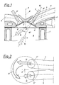
- einen Teilschnitt durch eine Brennkraftmaschinen gemäß der Erfindung,
- Fig. 2
- hiezu eine Draufsicht,
- Fig. 3 und 4
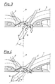
- je ein Detail zur Ausführung nach Fig. 1 und 2,
- Fig. 5 und 6
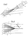
- eine andere Ausführungsform gemäß der Erfindung im Längsschnitt durch einen Ansaugkanal bzw. in Draufsicht,
- Fig. 7
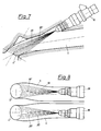
- eine weitere Ausführung nach der Erfindung und
- Fig. 8
- dazu den Grundriß,
- Fig. 9 und 10
- je Ventilhubkurven zu einer Variante gemäß der Erfindung.
- Fig. 1
- 2 shows a partial section through an internal combustion engine according to the invention,
- Fig. 2
- like a top view,
- 3 and 4
- one detail each for the embodiment according to FIGS. 1 and 2,
- 5 and 6
- another embodiment according to the invention in longitudinal section through an intake duct or in plan view,
- Fig. 7
- a further embodiment according to the invention and
- Fig. 8
- plus the floor plan,
- 9 and 10
- per valve lift curves for a variant according to the invention.
Bei der in den Fig. 1 und 2 dargestellten erfindungsgemäßen Brennkraftmaschine ist der Zylinderblock mit 1 und der auf diesem befestigte Zylinderkopf mit 2 bezeichnet. Im Zylinderkopf 2 befinden sich der dachförmig begrenzte Brennraum 3, sowie die Einlaßkanäle 4 und 5 und der Auslaßkanal 6 bzw. die Auslaßkanäle 6. Die zugehörigen Ein- bzw. Auslaßventile sind mit 4′ bzw. 6′ und die zugehörigen Querschnitte mit 4˝ bzw. 5˝ und 6˝ bezeichnet.In the internal combustion engine according to the invention shown in FIGS. 1 and 2, the cylinder block is denoted by 1 and the cylinder head fastened thereon by 2. In the
Der Einlaßkanal 5 mündet als sogenannter Neutralkanal unter einem vergleichsweise spitzen Winkel 7 zu der durch die Motorzylinderachsen 8′ einer Zylinderreihe bestimmten Symmetrieebene 8 in den Brennraum 3 bzw. in den Raum 9. Der Einlaßkanal 5 ist so ausgebildet, daß sich eine Hauptströmungsrichtung des angesaugten Gemisch-Teilstromes unter einem geringen Winkel 7 zur Symmetrieebene 8 ergibt. Dabei ist die Kanalausbildung so gewählt, daß eine möglichst gleichmäßige Beaufschlagung des gesamten Einlaßventiltellers durch die Einlaßströmung erfolgt - vergleiche Fig. 3 - und sich eine Hauptströmungsrichtung etwa in Richtung der Einlaßventilachse 10′ ergibt, welche durch den gestrichelt gezeichneten Pfeil 10 angedeutet ist. Der Einlaßkanal 5 ist in Fig. 1 gestrichelt eingezeichnet.The
Der zweite Einlaßkanal 4, der sogenannte Tangentialkanal, mündet unter einem Winkel 11 zur Symmetrieebene 8 in den Brennraum 3 bzw. Motorraum 9, welcher Winkel um 10-40° größer ist als der Winkel 7. Dieser Winkel 11 ist so ausgelegt, daß sich eine Hauptströmungsrichtung des angesaugten Gemischanteiles unter möglichst großem Winkel zur Symmetrieebene ergibt, welche durch den voll ausgezogenen Pfeil 12 in Fig. 1 und 4 dargestellt ist. Durch die spezielle Ausbildung dieses Einlaßkanales 4 wird vor allem der den Auslaßventilen 6′ näherliegende Teil der Ventilteller von der Einlaßströmung beaufschlagt, wie in Fig. 4 veranschaulicht ist. Durch den flachen Eintrittswinkel des Einlaßkanals 4 in den Brennraum 3 bzw. Zylinderraum 9 und die zusätzliche stark asymmetrische Umlenkung am Ventilteller, wie in Fig. 4 dargestellt, ergibt sich eine sehr flach liegende Haupteinströmrichtung, wie durch den voll ausgezogenen Pfeil 12 veranschaulicht ist.The
Wie in Fig. 2 dargestellt, liegen die beiden Einlaßkanäle 4 und 5 zu beiden Seiten einer Normalebene 8˝ auf die Symmetrieebene 8. Wesentlich für die Erfindung ist, daß der Winkel des Teilstroms 12 auf einer Seite der Normalebene 8˝ um 10 bis 40° größer ist als der Winkel 7 des Teilstromes 10 auf der gegenüberliegenden Seite der Normalebene 8˝.As shown in Fig. 2, the two
Bei der vorliegenden Erfindung weist die unter geringem Winkel 7 zur Symmetrieebene 8 durch den Neutralkanal 5 einströmende Masse einen wesentlich geringeren Impuls senkrecht zur Symmetrieebene 8 auf, als die durch den Tangentialkanal 4 einströmende Masse. Dadurch wird sowohl eine Drallbewegung um eine zur Kurbelwelle parallele Achse, als auch eine Drallbewegung um eine zur Zylinderachse 8′ parallele Achse initiiert. Diese erhöhte Ladungsbewegung führt vor allem unter Teillastbedingungen zu einem schnelleren Verbrennungsablauf, insbesondere zur deutlich verkürzten Entflammungsphase.In the present invention, the mass flowing in through the
Zusätzlich kann durch diese Ladungsbewegung eine in den Einlaßkanälen eingeleitete Ladungsschichtung mit unterschiedlichem Mischungsverhältnis Kraftstoff/Luft im Brennraum in einer den Verbrennungsablauf begünstigenden Form initiiert und bis zur Zündung aufrecht erhalten werden. Daraus resultiert sowohl eine höhere Verbrennungsstabilität, verbesserte Abmagerbarkeit und größere Toleranz gegenüber Hauptgasrückführung sowie daraus resultierenden Verbesserungen bezüglich Kraftstoffverbrauch und Schadstoffemissionen.In addition, this charge movement can initiate a charge stratification introduced in the inlet channels with a different fuel / air mixture ratio in the combustion chamber in a form which favors the combustion process and can be maintained until ignition. This results in higher combustion stability, improved leanability and greater tolerance to main gas recirculation as well as the resulting improvements in fuel consumption and pollutant emissions.
Beim Ausführungsbeispiel gemäß Fig. 5 und 6 befindet sich im Neutralkanal 5 eine Drosseleinrichtung in Form einer Drosselklappe 14, wogegen der Tangentialkanal 4 ständig offen bleibt. Zwischen dem Tangentialkanal 4 und dem Neutralkanal 5 befindet sich eine genau definierte Öffnung 15, durch welche die beiden Strahlen 16 und 17 der Einspritzdüse 18 hindurchtreten, wobei sie mit ihren Achsen 16′ bzw. 17′ gegen die Mittel der Ventil-Einlaßquerschnitte 5˝ bzw. 4˝ gerichtet sind. Durch Beibehaltung gleicher Einspritzmengen in den beiden Einlaßkanälen, jedoch Drosselung des Luftstromes im Neutralkanal 5 wird vergleichsweise fettes Gemisch durch den Neutralakanal 5 und vergleichsweise mageres Gemisch durch den Tangentialkanal 4 angesaugt. Dadurch entsteht ein entsprechende Ladungsschichtung, wobei das zündfähigere fettere Gemisch im Bereich der Zündkerze zu liegen kommt.5 and 6 there is a throttle device in the form of a
Die Drosselung im Neutralkanal 5 durch die Drosselklappe 14 erfolgt gegebenenfalls unter Aufrechterhaltung einer definierten Leckluft und zusätzlich durch eine Querströmung aus dem Tangentialkanal durch die genau definierte Öffnung 15. Durch die spezielle Einlaßkanalgestaltung kann die Schichtung mit fettem Gemisch in Zündkerzennähe und magerem Gemisch in wandnahen Zonen bis zum Zündzeitpunkt aufrecht erhalten werden.The throttling in the
Die Ausführung nach Fig. 7 und 8 unterscheidet sich von jener nach den Fig. 5 und 6 dadurch, daß der Neutralkanal 5 und der Tangentialkanal 4 voneinander völlig getrennt geführt sind und je eine Einspritzdüse 18 aufweisen, deren Strahlen 19 bzw. 20 mit ihren Mittellinien 19′ bzw. 20′ gegen die Mittel der Ventil-Einlaßquerschnitte 5˝ bzw. 4˝ gerichtet sind. Durch Variation der durch die Düsen eingespritzten Kraftstoffmengen können beliebige Ladungsschichtungen erreicht werden.The embodiment according to FIGS. 7 and 8 differs from that according to FIGS. 5 and 6 in that the
Anstelle der Drosselung der durch den Neutralkanal 5 einströmenden Luftmasse, kann nicht nur durch ein Drosselorgan im Neutralkanal erfolgen, sondern auch durch Veränderung der Ventilhubkurve. Diese Veränderung der Ventilhubkurve kann, wie an sich bekannt, vorzugsweise durch frühes Schließen des Einlaßventiles bewirkt werden, was z.B. durch elektrohydraulische Ansteuerung eines Zwischenelementes zwischen Einlaßventil und Nockenwwelle bewirkt werden kann. Die Wirkung einer derartigen Einrichtung ist in Fig. 9 dargestellt, wo die Ventilerhebung H über den Kurbelwinkel KW aufgetragen ist. Eine andere Möglichkeit besteht darin, den maximalen Einlaßventilhub H zu variieren, wie in Fig. 10 dargestellt.Instead of throttling the air mass flowing through the
Claims (9)
- An internal combustion engine with at least two inlet valves for each engine cylinder, which in their closed position are equidistant from a plane normal to the cylinder axis (8′), and with a combustion chamber (3) defined by roof-shaped boundary surfaces in the cylinder head (2), the main flow directions of the partial streams (10, 12) admitted into the combustion chamber (3) through the inlet valves (4′, 5′) each forming an acute angle with the plane defined by the cylinder axes (8′) of a cylinder bank, i.e., the symmetry plane (8), and the partial streams (10, 12) entering the combustion chamber (3) through inlets (4", 5") located one on either side of a plane (8") going through the cylinder axis (8′) and being normal to the symmetry plane (8), characterized in that the angle (11) of at least one partial stream (12) on one side of a plane (8") going through the cylinder axis (8′) and being normal to the symmetry plane (8) is larger by 10 to 40° than the angle (7) of at least one corresponding partial stream (10) on the other side of said normal plane (8"), the angles (7, 11) of the partial streams (10, 12) relative to the symmetry plane (8) being determined by the configuration of the intake passages (4, 5) leading towards the inlet valves (4′, 5′), such that both a rotary motion about an axis parallel to the crankshaft and a rotary motion (13) about an axis parallel to the cylinder axis (8′) is initiated in such a way as to prevent the partial streams from interfering with each other.
- An internal combustion engine according to claim 1, characterized in that the axis (10") of the intake passage (5) towards the first inlet valve (5′) coincides with the axis (10′) of the said inlet valve (5′), at least immediately before this inlet valve (5′), or is parallel thereto, and that the axis (12′) of the intake passage (4) towards the second inlet valve (4′) forms an acute angle with the axis (10′) of the said inlet valve (4′), at least immediately before this second inlet valve (4′).
- An internal combustion engine according to claim 1 or 2, characterized in that the intake passages (4, 5) run separately both in the cylinder head (2) and in the intake manifold until they open into a joint manifold serving several engine cylinders.
- An internal combustion engine according to any of claims 1 to 3, characterized in that a fuel injection valve (18) is provided in each of the two intake passages (4, 5), the respective amount of fuel to be injected by each valve (18) varying with the specific operating conditions of the engine (load, speed).
- An internal combustion engine according to claim 1 or 2, characterized in that the intake passages (4, 5) run separately until they open into a joint manifold serving several engine cylinders, while a defined opening (15) is provided between the two intake passages (4, 5) in the vicinity of the inlet valves (4′, 5′).
- An internal combustion engine according to claim 5, characterized in that one injection valve (18) per engine cylinder is arranged symmetrically to the two intake passages (4, 5) in such a way that the two fuel jets (16, 17) of this injection valve (18) are directed towards the disks of the inlet valves through the defined opening (15).
- An internal combustion engine according to any of claims 1 to 3, characterized in that mixture formation takes place in the combustion chamber (3) itself, for instance, by high-pressure airless injection or fuel air injection into the combustion chamber.
- An internal combustion engine according to any of claims 1 to 7, characterized in that a throttle element (14) is provided in flow direction before the injection valve(s) (18) in that intake passage (5) from which the partial stream forming the smaller angle with the symmetry plane (8) emerges and in which the stream of intake air is throttled in correspondence with the operational state of the engine.
- An internal combustion engine according to claim 7, characterized in that throttling of the partial stream (10) of intake air forming the smaller angle with the symmetry plane (8) is effected by a change in the lift characteristic of the inlet valve (5′) in correspondence with the operational state of the engine.
Applications Claiming Priority (2)
| Application Number | Priority Date | Filing Date | Title |
|---|---|---|---|
| AT0043590A AT402535B (en) | 1990-02-23 | 1990-02-23 | INTERNAL COMBUSTION ENGINE WITH AT LEAST TWO INLET VALVES PER ENGINE CYLINDER |
| AT435/90 | 1990-02-23 |
Publications (2)
| Publication Number | Publication Date |
|---|---|
| EP0444018A1 EP0444018A1 (en) | 1991-08-28 |
| EP0444018B1 true EP0444018B1 (en) | 1994-08-10 |
Family
ID=3490536
Family Applications (1)
| Application Number | Title | Priority Date | Filing Date |
|---|---|---|---|
| EP91890033A Expired - Lifetime EP0444018B1 (en) | 1990-02-23 | 1991-02-19 | Internal combustion engine comprising at least two inlet valves per cylinder |
Country Status (4)
| Country | Link |
|---|---|
| US (1) | US5138989A (en) |
| EP (1) | EP0444018B1 (en) |
| AT (1) | AT402535B (en) |
| DE (1) | DE59102460D1 (en) |
Families Citing this family (37)
| Publication number | Priority date | Publication date | Assignee | Title |
|---|---|---|---|---|
| KR950011323B1 (en) * | 1991-05-14 | 1995-09-30 | 마쯔다 가부시기가이샤 | Combustion chamber structure for an engine |
| US5301641A (en) * | 1991-11-06 | 1994-04-12 | Honda Giken Kogyo Kabushiki Kaisha | Internal combustion engine |
| JP3003339B2 (en) * | 1991-12-06 | 2000-01-24 | トヨタ自動車株式会社 | Intake system for fuel injection type internal combustion engine |
| FR2712028B1 (en) * | 1993-11-04 | 1995-12-15 | Renault | Internal combustion engine with indirect fuel injection. |
| JPH07150945A (en) * | 1993-11-26 | 1995-06-13 | Yamaha Motor Co Ltd | Combustion chamber structure for four cycle engine |
| AT405672B (en) * | 1994-03-31 | 1999-10-25 | Avl Verbrennungskraft Messtech | METHOD FOR INPUTING FUEL INTO THE COMBUSTION CHAMBER OF AN INTERNAL COMBUSTION ENGINE |
| EP0676533B1 (en) * | 1994-04-09 | 1997-09-24 | Adam Opel Ag | Inlet passage system for an internal combustion engine |
| US5551401A (en) * | 1994-05-31 | 1996-09-03 | Suzuki Motor Corporation | Air suction system for internal combustion engine |
| FR2727722A1 (en) * | 1994-12-01 | 1996-06-07 | Magneti Marelli France | FUEL DISPERSION SKIRT FOR INJECTOR OF AN INJECTION ENGINE |
| JPH08200023A (en) * | 1995-01-24 | 1996-08-06 | Toyota Motor Corp | Cylinder head structure of internal combustion engine |
| IT1285853B1 (en) * | 1996-04-24 | 1998-06-24 | Fiat Ricerche | INTERNAL COMBUSTION ENGINE WITH VARIABLE OPERATION VALVES. |
| JPH108971A (en) * | 1996-06-19 | 1998-01-13 | Yamaha Motor Co Ltd | Cylinder fuel injection engine |
| AT2434U1 (en) * | 1997-10-21 | 1998-10-27 | Avl List Gmbh | COMBUSTION IGNITION ENGINE |
| AT2489U1 (en) * | 1997-11-20 | 1998-11-25 | Avl List Gmbh | PISTON PISTON INTERNAL COMBUSTION ENGINE |
| JP3939864B2 (en) * | 1998-08-27 | 2007-07-04 | ヤマハ発動機株式会社 | In-cylinder injection engine |
| AT3138U1 (en) * | 1998-11-16 | 1999-10-25 | Avl List Gmbh | FOUR-STROKE COMBUSTION ENGINE WITH AT LEAST TWO INLET VALVES PER CYLINDER |
| GB9920666D0 (en) | 1999-09-01 | 1999-11-03 | Zalkin Anthony L | Improved internal combustion engine |
| AT4966U1 (en) * | 2000-03-14 | 2002-01-25 | Avl List Gmbh | FOUR-STOCK COMBUSTION ENGINE WITH AT LEAST TWO INLET VALVES |
| AT4788U1 (en) | 2000-06-28 | 2001-11-26 | Avl List Gmbh | INTERNAL COMBUSTION ENGINE |
| AT5137U1 (en) * | 2000-09-21 | 2002-03-25 | Avl List Gmbh | FOUR-STROKE COMBUSTION ENGINE WITH AT LEAST TWO INLET VALVES PER CYLINDER |
| EP1191211B1 (en) | 2000-09-21 | 2004-08-11 | AVL List GmbH | Method for operating an internal combustion engine |
| AT5781U1 (en) * | 2001-04-19 | 2002-11-25 | Avl List Gmbh | INTERNAL COMBUSTION ENGINE WITH AT LEAST ONE INLET VALVE |
| AT5648U1 (en) * | 2001-08-02 | 2002-09-25 | Avl List Gmbh | INTERNAL COMBUSTION ENGINE WITH AT LEAST TWO INLET VALVES PER CYLINDER |
| AT500408B8 (en) * | 2004-10-04 | 2007-02-15 | Avl List Gmbh | INTERNAL COMBUSTION ENGINE WITH AT LEAST TWO INTAKE CHANNELS PER CYLINDER |
| JP2005307904A (en) * | 2004-04-23 | 2005-11-04 | Denso Corp | Fuel injection system |
| JP2006070860A (en) * | 2004-09-06 | 2006-03-16 | Honda Motor Co Ltd | Intake port structure for internal combustion engine |
| FR2879666B1 (en) * | 2004-12-21 | 2010-01-15 | Inst Francais Du Petrole | METHOD FOR CONTROLLING A SUPERIOR INTERNAL COMBUSTION ENGINE WITH COMMAND IGNITION, ESPECIALLY OF GASOLINE TYPE |
| US7565894B2 (en) * | 2005-09-12 | 2009-07-28 | Hitachi, Ltd. | Fuel injection apparatus for and method of internal combustion engine, and fuel injection valve |
| AT500926B1 (en) * | 2006-01-10 | 2007-12-15 | Avl List Gmbh | INTERNAL COMBUSTION ENGINE, IN PARTICULAR CHARGED INTERNAL COMBUSTION ENGINE |
| US7347178B2 (en) * | 2006-01-12 | 2008-03-25 | Ford Global Technologies, Llc | System and method for controlling auto-ignition |
| US20090241905A1 (en) * | 2006-03-29 | 2009-10-01 | Denso Corporation | Mount structure of fuel injection valve and fuel injection system |
| AT506469B1 (en) | 2009-03-26 | 2010-12-15 | Avl List Gmbh | Internal combustion engine |
| EP2418365B1 (en) * | 2010-08-12 | 2012-07-18 | C.R.F. Società Consortile per Azioni | Combustion chamber for diesel engines with inclined engine valves |
| JP5541535B2 (en) * | 2011-09-13 | 2014-07-09 | 日立オートモティブシステムズ株式会社 | Fuel injection control device for internal combustion engine |
| US9657633B2 (en) * | 2012-04-25 | 2017-05-23 | International Engine Intellectual Property Company, Llc. | Swirl-inducing intake valve arrangement |
| US10774730B2 (en) * | 2013-11-12 | 2020-09-15 | Nautilus Engineering, Llc | Systems and methods of forced air induction in internal combustion engines |
| DE102017216996B3 (en) | 2017-09-26 | 2019-01-17 | Bayerische Motoren Werke Aktiengesellschaft | internal combustion engine |
Citations (2)
| Publication number | Priority date | Publication date | Assignee | Title |
|---|---|---|---|---|
| JPS60108529A (en) * | 1983-11-17 | 1985-06-14 | Mazda Motor Corp | Suction device of engine |
| DE3502699A1 (en) * | 1984-01-26 | 1985-08-14 | Mazda Motor Corp., Hiroshima | SUCTION DEVICE FOR PISTON INTERNAL COMBUSTION ENGINE |
Family Cites Families (12)
| Publication number | Priority date | Publication date | Assignee | Title |
|---|---|---|---|---|
| JPS5845571B2 (en) * | 1978-01-12 | 1983-10-11 | 日産自動車株式会社 | Combustion chamber of internal combustion engine |
| GB2113759A (en) * | 1982-01-21 | 1983-08-10 | Ricardo Consulting Eng | Combustion chamber arrangements in ic engines |
| US4548175A (en) * | 1983-12-05 | 1985-10-22 | Toyota Jidosha Kabushiki Kaisha | Internal combustion engine with two intake valves |
| FR2584455B1 (en) * | 1985-07-08 | 1989-07-28 | Peugeot | INTERNAL COMBUSTION ENGINE CYLINDER HEAD WITH THREE VALVES |
| JPS62228622A (en) * | 1986-03-31 | 1987-10-07 | Yamaha Motor Co Ltd | Suction device for engine |
| JPS62284919A (en) * | 1986-06-04 | 1987-12-10 | Mazda Motor Corp | Combustion chamber structure for engine |
| JPH0755330Y2 (en) * | 1987-12-18 | 1995-12-20 | 三菱自動車工業株式会社 | Internal combustion engine with three intake valves |
| IT1223543B (en) * | 1987-12-18 | 1990-09-19 | Alfa Lancia Ind | SUCTION DEVICE FOR A C.I.MOTOR multi-cylinder |
| JPH0745817B2 (en) * | 1988-02-12 | 1995-05-17 | 本田技研工業株式会社 | Direct injection multi-cylinder diesel engine |
| JPH068604B2 (en) * | 1988-05-23 | 1994-02-02 | 本田技研工業株式会社 | Valve operating state switching device for internal combustion engine |
| JPH0733766B2 (en) * | 1988-08-30 | 1995-04-12 | トヨタ自動車株式会社 | Combustion chamber of internal combustion engine |
| JPH02149769A (en) * | 1988-11-30 | 1990-06-08 | Fuji Heavy Ind Ltd | Ignition plug arrangement device of four valve type engine combustion chamber |
-
1990
- 1990-02-23 AT AT0043590A patent/AT402535B/en not_active IP Right Cessation
-
1991
- 1991-02-19 DE DE59102460T patent/DE59102460D1/en not_active Expired - Fee Related
- 1991-02-19 EP EP91890033A patent/EP0444018B1/en not_active Expired - Lifetime
- 1991-02-20 US US07/657,857 patent/US5138989A/en not_active Expired - Lifetime
Patent Citations (2)
| Publication number | Priority date | Publication date | Assignee | Title |
|---|---|---|---|---|
| JPS60108529A (en) * | 1983-11-17 | 1985-06-14 | Mazda Motor Corp | Suction device of engine |
| DE3502699A1 (en) * | 1984-01-26 | 1985-08-14 | Mazda Motor Corp., Hiroshima | SUCTION DEVICE FOR PISTON INTERNAL COMBUSTION ENGINE |
Also Published As
| Publication number | Publication date |
|---|---|
| ATA43590A (en) | 1996-10-15 |
| DE59102460D1 (en) | 1994-09-15 |
| US5138989A (en) | 1992-08-18 |
| AT402535B (en) | 1997-06-25 |
| EP0444018A1 (en) | 1991-08-28 |
Similar Documents
| Publication | Publication Date | Title |
|---|---|---|
| EP0444018B1 (en) | Internal combustion engine comprising at least two inlet valves per cylinder | |
| DE3444356C2 (en) | ||
| DE3828742C2 (en) | ||
| DE4439918C2 (en) | Device for supplying a fuel / air mixture to an internal combustion engine | |
| DE3600408C2 (en) | ||
| DE3713628C2 (en) | Intake system for internal combustion engines | |
| DE2803533A1 (en) | AIR COMPRESSING, SELF-IGNING COMBUSTION ENGINE | |
| DE3638021C2 (en) | Intake system for an internal combustion engine | |
| DE4439921C2 (en) | Intake system of an internal combustion engine | |
| AT402326B (en) | CYLINDER HEAD FOR AN INTERNAL COMBUSTION ENGINE | |
| DE19622891C2 (en) | Exhaust gas recirculation system | |
| EP0764773B1 (en) | Four stroke internal combustion engine | |
| DE2854332A1 (en) | COMBUSTION ENGINE | |
| EP0911502B1 (en) | Spark-ignited combustion engine | |
| DE10110986B4 (en) | Four-stroke internal combustion engine with at least two intake valves | |
| DE3718083C2 (en) | ||
| EP0676533B1 (en) | Inlet passage system for an internal combustion engine | |
| DE3903831C2 (en) | ||
| DE3936263A1 (en) | IC engine with two inlet valves per cylinder - has system to control degree of swirl in air flowing to each valve | |
| DE3836550A1 (en) | Inlet port system for an internal combustion engine with two inlet valves per cylinder arranged in the cylinder head | |
| DE4205237C2 (en) | Intake channel in a cylinder head of an internal combustion engine with at least two intake valves per cylinder | |
| EP1134403B1 (en) | Combustion engine with exhaust gas recirculation | |
| EP1290320B1 (en) | Fuel injection system and method for the injection of fuel | |
| DE4420063A1 (en) | Fuel injection valve for IC engines | |
| DE2932627A1 (en) | One-way scavenged two=stroke IC-engine - has upper row of non radial inlet ports normal to, and lower radial row inclined up into cylinder |
Legal Events
| Date | Code | Title | Description |
|---|---|---|---|
| PUAI | Public reference made under article 153(3) epc to a published international application that has entered the european phase |
Free format text: ORIGINAL CODE: 0009012 |
|
| AK | Designated contracting states |
Kind code of ref document: A1 Designated state(s): DE FR GB IT SE |
|
| GBC | Gb: translation of claims filed (gb section 78(7)/1977) | ||
| EL | Fr: translation of claims filed | ||
| 17P | Request for examination filed |
Effective date: 19911008 |
|
| 17Q | First examination report despatched |
Effective date: 19920416 |
|
| GRAA | (expected) grant |
Free format text: ORIGINAL CODE: 0009210 |
|
| AK | Designated contracting states |
Kind code of ref document: B1 Designated state(s): DE FR GB IT SE |
|
| REF | Corresponds to: |
Ref document number: 59102460 Country of ref document: DE Date of ref document: 19940915 |
|
| ET | Fr: translation filed | ||
| GBT | Gb: translation of ep patent filed (gb section 77(6)(a)/1977) |
Effective date: 19940901 |
|
| ITF | It: translation for a ep patent filed |
Owner name: MODIANO & ASSOCIATI S.R.L. |
|
| EAL | Se: european patent in force in sweden |
Ref document number: 91890033.3 |
|
| PLBE | No opposition filed within time limit |
Free format text: ORIGINAL CODE: 0009261 |
|
| STAA | Information on the status of an ep patent application or granted ep patent |
Free format text: STATUS: NO OPPOSITION FILED WITHIN TIME LIMIT |
|
| 26N | No opposition filed | ||
| REG | Reference to a national code |
Ref country code: GB Ref legal event code: IF02 |
|
| PGFP | Annual fee paid to national office [announced via postgrant information from national office to epo] |
Ref country code: SE Payment date: 20020227 Year of fee payment: 12 |
|
| PG25 | Lapsed in a contracting state [announced via postgrant information from national office to epo] |
Ref country code: SE Free format text: LAPSE BECAUSE OF NON-PAYMENT OF DUE FEES Effective date: 20030220 |
|
| EUG | Se: european patent has lapsed | ||
| PGFP | Annual fee paid to national office [announced via postgrant information from national office to epo] |
Ref country code: GB Payment date: 20070214 Year of fee payment: 17 |
|
| PGFP | Annual fee paid to national office [announced via postgrant information from national office to epo] |
Ref country code: IT Payment date: 20070514 Year of fee payment: 17 |
|
| PGFP | Annual fee paid to national office [announced via postgrant information from national office to epo] |
Ref country code: FR Payment date: 20070226 Year of fee payment: 17 |
|
| PGFP | Annual fee paid to national office [announced via postgrant information from national office to epo] |
Ref country code: DE Payment date: 20080429 Year of fee payment: 18 |
|
| GBPC | Gb: european patent ceased through non-payment of renewal fee |
Effective date: 20080219 |
|
| REG | Reference to a national code |
Ref country code: FR Ref legal event code: ST Effective date: 20081031 |
|
| PG25 | Lapsed in a contracting state [announced via postgrant information from national office to epo] |
Ref country code: FR Free format text: LAPSE BECAUSE OF NON-PAYMENT OF DUE FEES Effective date: 20080229 |
|
| PG25 | Lapsed in a contracting state [announced via postgrant information from national office to epo] |
Ref country code: GB Free format text: LAPSE BECAUSE OF NON-PAYMENT OF DUE FEES Effective date: 20080219 |
|
| PG25 | Lapsed in a contracting state [announced via postgrant information from national office to epo] |
Ref country code: IT Free format text: LAPSE BECAUSE OF NON-PAYMENT OF DUE FEES Effective date: 20080219 |
|
| PG25 | Lapsed in a contracting state [announced via postgrant information from national office to epo] |
Ref country code: DE Free format text: LAPSE BECAUSE OF NON-PAYMENT OF DUE FEES Effective date: 20090901 |