EP0443585A2 - Dispositif et procédé pour commander le fonctionnement de l'inverseur - Google Patents
Dispositif et procédé pour commander le fonctionnement de l'inverseur Download PDFInfo
- Publication number
- EP0443585A2 EP0443585A2 EP91102561A EP91102561A EP0443585A2 EP 0443585 A2 EP0443585 A2 EP 0443585A2 EP 91102561 A EP91102561 A EP 91102561A EP 91102561 A EP91102561 A EP 91102561A EP 0443585 A2 EP0443585 A2 EP 0443585A2
- Authority
- EP
- European Patent Office
- Prior art keywords
- operation command
- inverter
- command
- command group
- commands
- Prior art date
- Legal status (The legal status is an assumption and is not a legal conclusion. Google has not performed a legal analysis and makes no representation as to the accuracy of the status listed.)
- Granted
Links
Images


Classifications
-
- H—ELECTRICITY
- H02—GENERATION; CONVERSION OR DISTRIBUTION OF ELECTRIC POWER
- H02P—CONTROL OR REGULATION OF ELECTRIC MOTORS, ELECTRIC GENERATORS OR DYNAMO-ELECTRIC CONVERTERS; CONTROLLING TRANSFORMERS, REACTORS OR CHOKE COILS
- H02P27/00—Arrangements or methods for the control of AC motors characterised by the kind of supply voltage
- H02P27/04—Arrangements or methods for the control of AC motors characterised by the kind of supply voltage using variable-frequency supply voltage, e.g. inverter or converter supply voltage
- H02P27/06—Arrangements or methods for the control of AC motors characterised by the kind of supply voltage using variable-frequency supply voltage, e.g. inverter or converter supply voltage using DC to AC converters or inverters
- H02P27/08—Arrangements or methods for the control of AC motors characterised by the kind of supply voltage using variable-frequency supply voltage, e.g. inverter or converter supply voltage using DC to AC converters or inverters with pulse width modulation
-
- H—ELECTRICITY
- H02—GENERATION; CONVERSION OR DISTRIBUTION OF ELECTRIC POWER
- H02M—APPARATUS FOR CONVERSION BETWEEN AC AND AC, BETWEEN AC AND DC, OR BETWEEN DC AND DC, AND FOR USE WITH MAINS OR SIMILAR POWER SUPPLY SYSTEMS; CONVERSION OF DC OR AC INPUT POWER INTO SURGE OUTPUT POWER; CONTROL OR REGULATION THEREOF
- H02M7/00—Conversion of AC power input into DC power output; Conversion of DC power input into AC power output
- H02M7/42—Conversion of DC power input into AC power output without possibility of reversal
- H02M7/44—Conversion of DC power input into AC power output without possibility of reversal by static converters
- H02M7/48—Conversion of DC power input into AC power output without possibility of reversal by static converters using discharge tubes with control electrode or semiconductor devices with control electrode
- H02M7/53—Conversion of DC power input into AC power output without possibility of reversal by static converters using discharge tubes with control electrode or semiconductor devices with control electrode using devices of a triode or transistor type requiring continuous application of a control signal
- H02M7/537—Conversion of DC power input into AC power output without possibility of reversal by static converters using discharge tubes with control electrode or semiconductor devices with control electrode using devices of a triode or transistor type requiring continuous application of a control signal using semiconductor devices only, e.g. single switched pulse inverters
- H02M7/5387—Conversion of DC power input into AC power output without possibility of reversal by static converters using discharge tubes with control electrode or semiconductor devices with control electrode using devices of a triode or transistor type requiring continuous application of a control signal using semiconductor devices only, e.g. single switched pulse inverters in a bridge configuration
- H02M7/53871—Conversion of DC power input into AC power output without possibility of reversal by static converters using discharge tubes with control electrode or semiconductor devices with control electrode using devices of a triode or transistor type requiring continuous application of a control signal using semiconductor devices only, e.g. single switched pulse inverters in a bridge configuration with automatic control of output voltage or current
- H02M7/53873—Conversion of DC power input into AC power output without possibility of reversal by static converters using discharge tubes with control electrode or semiconductor devices with control electrode using devices of a triode or transistor type requiring continuous application of a control signal using semiconductor devices only, e.g. single switched pulse inverters in a bridge configuration with automatic control of output voltage or current with digital control
-
- H—ELECTRICITY
- H02—GENERATION; CONVERSION OR DISTRIBUTION OF ELECTRIC POWER
- H02P—CONTROL OR REGULATION OF ELECTRIC MOTORS, ELECTRIC GENERATORS OR DYNAMO-ELECTRIC CONVERTERS; CONTROLLING TRANSFORMERS, REACTORS OR CHOKE COILS
- H02P23/00—Arrangements or methods for the control of AC motors characterised by a control method other than vector control
- H02P23/0077—Characterised by the use of a particular software algorithm
Definitions
- the present invention relates to an operation command apparatus and process for selecting and setting operation commands, such as frequency and voltage, required to operate an induction motor controlled by an inventer unit.
- Fig. 6 is a block diagram illustrating a conventional inverter operation command unit disclosed in Japanese Patent Disclosure Bulletin No. 1989-26393.
- the numeral (1) indicates a three-phase alternating-current (AC) power supply, (2) a converter circuit (rectifying circuit) for converting a three-phase AC voltage output by the three-phase power supply (1) into a direct-current (DC) voltage, (3) a smoothing capacitor, (4) an inverter circuit for converting the DC voltage into an AC voltage of a predetermined frequency by on/off switching six switching elements at determined timing ( i.e ., a PWM control pattern), and (5) an induction motor driven at the AC voltage of the inverter circuit (4).
- AC alternating-current
- DC direct-current
- the inverter operation command unit is divided into an operation command device (200) and an inverter control circuit (300) connected by a connector (20).
- the operation command device (200) comprises keys (21), a keying-in means (22), a command data/command value judging means (23), a sending means (24), a receiving means (25), a display data output means (26), and an alphanumeric character display board (27).
- the inverter control circuit (300) comprises the converter circuit (2), the smoothing capacitor (3), the inverter circuit (4), a command value acceptance judging means (31), a nonvolatile memory (hereinafter referred to as the "EEROM”) allowing stored data to be electrically written and erased (32), and an inverter operation means (hereinafter referred to as the "base amplifier circuit”) (33).
- the keying-in means (22), a command data/command value judging means (23), the sending means (24), the receiving means (25) and the command value acceptance judging means (31) are functions generated by executing a predetermined operation program by means of a microprocessor (not illustrated) and are indicated as shown in Fig. 6 to simplify the description.
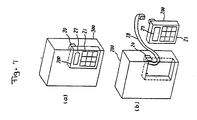
- the inverter operation command unit allows the operation command device (200) to be removed from and reconnected to the qinverter control circuit (300).
- the operation command device (200) and the inverter control circuit (300) may be connected using a long cable (28).
- Fig. 8 illustrates details of the button keys (21), wherein operation commands necessary to control the induction motor (5) by means of the inverter unit will be described by way of example.
- the inverter unit is employed to control the speed of the induction motor (5) by setting the individual operation commands indicated in Fig. 9 to optimum values in consideration of the load characteristics, such as the machine, connected to the induction motor (5) and those of induction motor (5) itself.
- operation command No. 1 "torque boost" indicated in Fig. 9 is used to adjust the output torque of the induction motor (5) and allows ten incremental settings e.g ., 1 to 10.
- the other operation commands shown in Fig. 9 can be set within predetermined ranges.
- the inverter unit allows command numbers corresponding to the operation commands to be entered and set from the keyboard (21a) having button keys (21).
- numeral keys 0 to 9 are used to set a command number or operation command data.
- ".” is a decimal point employed when setting the operation command data.
- "F1” is used to indicate that the following command number is one digit in length.
- “F2” is used when the command number is two digits in length.
- W is used to set data corresponding to a given command number.
- “R” is employed to read set data corresponding to a given command number.
- the keystrokes for changing a set value, e.g., 5, of operation command number 1 "torque boost" (see Fig. 9) to a new value, e.g. , 8, are as follows:
- 100 operation commands 0 to 99, can be provided.
- the set data is processed by the command data/command value judging means (23), the sending means (24) and the command value acceptance judging means (31), and stored in the EEROM (32).
- the EEROM (32) is provided with memory spaces in correspondence with the command numbers.
- the command data stored in the EEROM (32) is rewritten or read by decoding an instruction from the keyboard (21a) by means of the command data/command value judging means (23), the sending means (24) and the command value acceptance judging means (31).
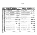
- the operation commands are set as shown in Fig. 10, e.g ., operation command No. 1, torque boost, is set to "5 (%)," operation command No. 2, maximum frequency, to "60 (Hz),” .
- operation command information which is used to operate a particular induction motor (5).
- Fig. 10 shows a set operation command group composed of various operation commands. Any of these commands can be called and displayed on the alphanumeric display panel (27) by entering the required data from the keyboard (21a).
- Fig. 11 is a flowchart illustrating operation of the operation command device (200)
- Fig. 12 is a flowchart showing operation of the inverter control circuit (300).
- the keying-in means (22) waits for any of the button keys (21) to be pressed.
- the keying-in means (22) judges whether the key pressed relates to command data, command value or command write.
- the command data/command value judging means (23) judges the command data or the command value of that key.
- the display data output means (26) displays the command data or the command value judged by the command data/command value judging means (23) on the alphanumeric character display board (27).
- pressing the key "8" causes the command data/command value judging means (23) to judge that the operation command of interest is the acceleration time, thus (after pressing "R") the acceleration time is displayed.
- the display enables a user to confirm that the command value is correct or that a new value has been accepted so that the user may then move on to the next command data or command value.
- the command data/command value judging means (23) judges the entered command value to be the length of time from a stop state to a maximum output frequency. Therefore, if a command value "5" is entered, the length of time between the stop state and the maximum output frequency is set to 5 seconds.
- step S6 When the user confirms the acceptance of the command value from the display and presses the command write key, which is then confirmed by the command data/command value judging means (23), the sending means (24) transmits the operation command data and the command value, e.g. , acceleration time of 5 seconds, to the inverter control circuit (300). (step S6)
- the command value acceptance judging means (31) of the inverter control circuit (300) judges whether the induction motor (5) may be operated in accordance with the command data and command value (step S11). If operation may be performed according to the command received, the command value acceptance judging means (31) transmits an "acceptable" message to the receiving means (25) of the operation command device (200) (step S12) and also stores the operation command data and command value in the EEROM (32) (step S13). If the operation cannot be performed according to the command received, the command value acceptance judging means (31) transmits an "unacceptable" message to the receiving means (25) (step S14).
- the display data output means (26) judges whether the induction motor (5) can be operated (step S7), and displays on the alphanumeric character display board (2) whether the command can be executed (step S8) (step S9).
- the alphanumeric character display board (2) flickers the command data and the command value alternately to indicate that the command is executable.
- the alphanumeric character display board (2) flickers the command number and an error display alternately to indicate that the command is unexecutable.
- the inverter control circuit (300) controls the operation of the induction motor (5).
- the inverter control circuit (300) calculates acceleration, a(f0) (c/s2), at frequency, f0 (Hz: c/s), in accordance with the acceleration time, t, and operates the induction motor (5) according to those command values. For example, if the acceleration time of 5 seconds has been entered, the inverter control circuit (300) calculates the acceleration, a(f0), at the frequency f0, for the acceleration time of 5 seconds. Assuming that a maximum output frequency is f max , the acceleration, a(f0) is denoted by the following expression: where, "0 Hz" indicates that the induction motor (5) is at a stop.
- the command values of the inverter unit vary depending on the application. Even if the application is the same, the values must also be set according to the load condition. Hence, the user of the inverter unit must set each command value, requiring a change from the initial preset value, in accordance with the application and/or load conditions. Therefore, the user must alter many command data settings every time the application and/or the load conditions change.
- Japanese Utility Model Disclosure Bulletin No. 1989-6796 discloses a unit that employs a magnetic card for storing and reading values of various operation commands by means of a card reader and a read circuit installed on the inverter. Fig.
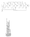
- FIG. 13 shows a block diagram of the aforementioned conventional unit which includes a three-phase AC power supply (11), a converter circuit (2) for converting a three-phase AC voltage output by the three-phase AC power supply (1) into a DC voltage, a smoothing capacitor (3), an inverter circuit (4), a microcomputer 6), a PWM control circuit (9), a base drive circuit (1), a reader (11) for reading set values from the magnetic card, and a setting circuit (12) for outputting various set values.
- the reader (11) reads the operation values stored on the magnetic card and outputs signals to the setting circuit (12), which then provides the signals entered by the reader (11) to the microcomputer (6).
- the setting circuit (12) When entry of the set values from the setting circuit (12) is complete, a start signal is provided from outside the inverter, and the microcomputer (6) performs program processing in accordance with the set values and drives the PWM control circuit (9).
- the operation command process of the conventional inverter operation command unit not only requires a lot of time to set commands but can also result in setting faults since the data for many operation commands must be rewritten every time the application or load conditions of the inverter unit change. Moreover, when re-setting the commands for prior application or load conditions, the previous set values must simply be recorded on paper, resulting in a complicated work process.
- a storage medium such as a magnetic card
- the cost of the equipment required is significant, e.g ., the reader (11) will significantly increase the price of the operation command unit.
- an object of the present invention to overcome the disadvantages in the conventional unit by providing an inverter operation command process which will allow data to be easily read and rewritten in accordance with the application and load conditions of the inverter unit.
- an inverter operation command process which utilizes the following steps: setting individually, multiple sets of operation commands required for the operation of an induction motor by means of an operation command input unit; storing a set of operation commands as a group into memory; and selecting and reading any of the multiple sets of operation command information from the said storage means for operation of the induction motor.
- the inverter operation command process individually sets multiple sets of operation commands required for the operation of the induction motor, stores operation command groups composed of sets of operation commands as single pieces of operation command information in the storage means, and reads any of the operation commands groups from the storage means for operation of the induction motor.
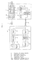
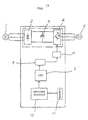
- Fig. 1 is a block diagram of an inverter operation command unit according to one embodiment of the present invention.
- Fig. 2 is a detailed view of button keys according to one embodiment of the present invention.
- Fig. 3 shows an operation command group according to one embodiment of the present invention.
- Fig. 4 is a general view of memory space according to one embodiment of the present invention.
- Fig. 5 is a flowchart illustrating an operation command process according to one embodiment of the present invention.
- Fig. 6 is a block diagram of an inverter operation command unit according to the conventional inverter command process.
- Fig. 7 is an outside view of the inverter operation command unit shown in Fig. 6.
- Fig. 8 is a detailed view of button keys of the inverter operation command unit shown in Fig. 6.
- Fig. 9 indicates operation information for use with the conventional inverter operation command process.
- Fig. 10 shows an operation command group according to the conventional inverter operation command process.
- Figs. 11 and 12 are flowcharts illustrating operation of the inverter operation command unit shown in Fig. 6.
- Fig. 13 is a block diagram of the inverter unit according to the conventional inverter command process.
- the numeral (1) indicates a three-phase AC power supply, (2) a converter circuit, (3) a smoothing capacitor, (4) an inverter circuit, (5) an induction motor, (22) a keying-in means, (23) an operation command data/command value judging means, (24) a sending means, (25) a receiving means, (26) a display data output means, (27) an alphanumeric character display board, (31) a command value acceptance judging means, (32) a storage means (EEROM), (33) an inverter operation means, (34) button keys, (201) an operation command device, and (300) an inverter control circuit.
- the numeral (201) indicates an operation command device and (300) an inverter control circuit identical to the one in the conventional unit, which are connected by a connector (2).
- the operation command device (201) comprises a keying-in means (22) for writing into EEROM (32) data entered by pressing button keys (34), an operation command data/command value judging means (23) for judging the contents of command values, a sending means (24), a receiving means (25), a display data output means (26) and an alphanumeric character display board (27).
- the keys (34) and the keying-in means (22) comprise an operation information inputting means, and the inverter control circuit (300) including the EEROM (32) as a storage means is identical to the one employed in the conventional unit.
- the keying-in means (22), the command data/command value judging means (23), the sending means (24), the receiving means (25) and the command value acceptance judging means (31) may be implemented by executing a predetermined operation program using a microprocessor (not illustrated).
- Fig. 2 is a detailed view of the keys (34).
- a "G" key not included in the keyboard (34a) of the conventional unit illustrated in Fig. 8 is provided.
- buttons (34) will now be described. With the keyboard (34a) shown in Fig. 2, the method for setting individual operation commands according to application and load conditions of the inverter unit is identical to that in the conventional unit and will not be further explained here.
- a second operation command group including the modified operation commands is set as a new operation command group separately from the previously entered operation command group and is stored in the EEROM (32).
- the operation command group thus set is operation command group G2 as shown in Fig. 3.
- FIG. 4 is a general view of the memory space of the EEROM (32), wherein addresses 0 to 99 are used to store data corresponding to up to 100 operation commands set in correspondence with a first application and load conditions. That is, addresses 0-99 are employed as a data area for the operation command group G1.
- Addresses 100 to 199 are employed to store data for up to 100 operation commands set corresponding to a second application purpose or load conditions. Namely, these addresses are employed as a data area for operation command group G2.
- step S20 is equivalent to steps S1 to S9 in Fig. 11.
- step S20 Whether the operation commands defined at step S20 will be stored as an operation command group is determined. If they are to be stored as an operation command group, the operation moves to step S22 and keys "GnW" of the keyboard (34a) are pressed , e.g. , according to the above described embodiment. Although “n” is not indicated it is an integer value 0, 1, 2, 3,... and corresponds to the address in the EEROM (32) for storing the operation command group.
- step S25 When it is not necessary to store the operation commands as an operation command group, the execution advances to step S25 to effect operation similar to that in the conventional unit.
- step S20 the command values are stored in the EEROM (32) at addresses different from those employed for the operation command group or groups already stored.
- an operation command group already stored may be read.
- the keys "G n R" are pressed to call up the relevant set of commands.
- the induction motor (5) is operated in accordance with the operation commands defined at the step S20 or the operation commands read at the step S24.
- step S23 the operation can change the operation command values, and resume operation.
- EEROM divides its memory space in correspondence with the command value sets in the above embodiment, only that data which differs from set 1 may be stored in areas for set 2 and subsequent data sets to economize on memory capacity.
- re-setting may be performed without needing to record previously set values on paper, by reading and recording the values in batches.
- the present invention provides an easily operated inverter operation command process, which allows the unit itself to be constructed at low cost without requiring a special reader to be installed separately for reading a magnetic card or the like.
- the invention achieves an inverter operation command process that will allow operation commands to be re-set in a short period of time and prevent faulty setting. This is accomplished by a process that employs an operation command group composed of the multiple operation commands required for the operation of the induction motor as one piece of operation command information, stores multiple operation command groups in the storage means, and reads a desired operation command groups from the storage means for the operation of the induction motor.
Landscapes
- Engineering & Computer Science (AREA)
- Power Engineering (AREA)
- Control Of Ac Motors In General (AREA)
- Inverter Devices (AREA)
Applications Claiming Priority (3)
| Application Number | Priority Date | Filing Date | Title |
|---|---|---|---|
| JP41499/90 | 1990-02-22 | ||
| JP4149990 | 1990-02-22 | ||
| JP2041499A JP2754835B2 (ja) | 1990-02-22 | 1990-02-22 | インバータの運転指令方法 |
Publications (3)
| Publication Number | Publication Date |
|---|---|
| EP0443585A2 true EP0443585A2 (fr) | 1991-08-28 |
| EP0443585A3 EP0443585A3 (en) | 1993-01-27 |
| EP0443585B1 EP0443585B1 (fr) | 1999-12-15 |
Family
ID=12610047
Family Applications (1)
| Application Number | Title | Priority Date | Filing Date |
|---|---|---|---|
| EP91102561A Expired - Lifetime EP0443585B1 (fr) | 1990-02-22 | 1991-02-21 | Dispositif et procédé pour commander le fonctionnement de l'inverseur |
Country Status (4)
| Country | Link |
|---|---|
| US (1) | US5497065A (fr) |
| EP (1) | EP0443585B1 (fr) |
| JP (1) | JP2754835B2 (fr) |
| DE (1) | DE69131841T2 (fr) |
Cited By (8)
| Publication number | Priority date | Publication date | Assignee | Title |
|---|---|---|---|---|
| EP0618519A1 (fr) * | 1993-04-01 | 1994-10-05 | Fuji Electric Co., Ltd. | Méthode pour introduire des constantes d'opération dans un onduleur |
| GB2288496A (en) * | 1994-03-30 | 1995-10-18 | Mitsubishi Electric Corp | Inverter operation command apparatus |
| FR2726134A1 (fr) * | 1994-10-19 | 1996-04-26 | Physic Plus Sarl | Onduleur a interrupteurs commandes permettant la visualisation et la selection des etapes de conversion |
| CN1036624C (zh) * | 1993-04-03 | 1997-12-03 | 富士电机株式会社 | 变换器装置的运转常数设定方法 |
| US6424871B1 (en) * | 1996-10-31 | 2002-07-23 | Ebara Corporation | Rotating machine integrated with controller, and inverter |
| KR100483542B1 (ko) * | 2001-09-12 | 2005-04-15 | 스미도모쥬기가이고교 가부시키가이샤 | 인버터가 있는 기어드 모터 |
| EP2169488A3 (fr) * | 2008-09-30 | 2010-12-22 | Rockwell Automation Technologies, Inc. | Module d'interface humaine pour commande de moteur |
| EP2439614A1 (fr) | 2010-09-16 | 2012-04-11 | ABB Oy | Convertisseur de fréquence doté d'un éditeur de texte |
Families Citing this family (2)
| Publication number | Priority date | Publication date | Assignee | Title |
|---|---|---|---|---|
| DE10101074B4 (de) * | 2001-01-11 | 2005-05-19 | Infineon Technologies Ag | Schaltungsanordnung zur Ansteuerung einer Last |
| FI121882B (fi) * | 2009-11-02 | 2011-05-31 | Kone Corp | Jarrutuslaitteisto, sähkökäyttö sekä hissijärjestelmä |
Family Cites Families (5)
| Publication number | Priority date | Publication date | Assignee | Title |
|---|---|---|---|---|
| JPS5959094A (ja) * | 1982-09-29 | 1984-04-04 | Toshiba Corp | 誘導電動機の速度制御装置 |
| DE3513775A1 (de) * | 1985-04-17 | 1986-10-23 | Arnold Müller GmbH & Co KG, 7312 Kirchheim | Steuereinheit fuer einen von einem frequenzumrichter gespeisten drehstrommotorantrieb |
| JPH0797908B2 (ja) * | 1986-07-23 | 1995-10-18 | 三菱電機株式会社 | 正弦波pwm信号発生装置 |
| JPH0750994B2 (ja) * | 1987-07-21 | 1995-05-31 | 三菱電機株式会社 | インバ−タの運転指令装置 |
| US4939437A (en) * | 1988-06-22 | 1990-07-03 | Siemens Energy & Automation, Inc. | Motor controller |
-
1990
- 1990-02-22 JP JP2041499A patent/JP2754835B2/ja not_active Expired - Lifetime
-
1991
- 1991-02-21 DE DE69131841T patent/DE69131841T2/de not_active Expired - Fee Related
- 1991-02-21 EP EP91102561A patent/EP0443585B1/fr not_active Expired - Lifetime
-
1994
- 1994-04-26 US US08/236,885 patent/US5497065A/en not_active Expired - Fee Related
Cited By (15)
| Publication number | Priority date | Publication date | Assignee | Title |
|---|---|---|---|---|
| US5442537A (en) * | 1993-04-01 | 1995-08-15 | Fuji Electric Co., Ltd. | Method for setting operation constants in an inverter device |
| EP0618519A1 (fr) * | 1993-04-01 | 1994-10-05 | Fuji Electric Co., Ltd. | Méthode pour introduire des constantes d'opération dans un onduleur |
| AU674669B2 (en) * | 1993-04-01 | 1997-01-09 | Fuji Electric Co., Ltd. | Method for setting operation constants in an inverter device |
| CN1036624C (zh) * | 1993-04-03 | 1997-12-03 | 富士电机株式会社 | 变换器装置的运转常数设定方法 |
| GB2288496B (en) * | 1994-03-30 | 1998-05-06 | Mitsubishi Electric Corp | Inverter operation command apparatus |
| GB2288496A (en) * | 1994-03-30 | 1995-10-18 | Mitsubishi Electric Corp | Inverter operation command apparatus |
| US5652701A (en) * | 1994-03-30 | 1997-07-29 | Mitsubishi Denki Kabushiki Kaisha | Inverter operation command apparatus |
| FR2726134A1 (fr) * | 1994-10-19 | 1996-04-26 | Physic Plus Sarl | Onduleur a interrupteurs commandes permettant la visualisation et la selection des etapes de conversion |
| US6424871B1 (en) * | 1996-10-31 | 2002-07-23 | Ebara Corporation | Rotating machine integrated with controller, and inverter |
| KR100483542B1 (ko) * | 2001-09-12 | 2005-04-15 | 스미도모쥬기가이고교 가부시키가이샤 | 인버터가 있는 기어드 모터 |
| EP2169488A3 (fr) * | 2008-09-30 | 2010-12-22 | Rockwell Automation Technologies, Inc. | Module d'interface humaine pour commande de moteur |
| US10282285B2 (en) | 2008-09-30 | 2019-05-07 | Rockwell Automation Technologies, Inc. | Human interface module for motor drive |
| US10606742B2 (en) | 2008-09-30 | 2020-03-31 | Rockwell Automation Technologies, Inc. | Human interface module for motor drive |
| EP2439614A1 (fr) | 2010-09-16 | 2012-04-11 | ABB Oy | Convertisseur de fréquence doté d'un éditeur de texte |
| US8683327B2 (en) | 2010-09-16 | 2014-03-25 | Abb Oy | Frequency converter with text editor |
Also Published As
| Publication number | Publication date |
|---|---|
| HK1010023A1 (en) | 1999-06-11 |
| EP0443585A3 (en) | 1993-01-27 |
| US5497065A (en) | 1996-03-05 |
| JP2754835B2 (ja) | 1998-05-20 |
| DE69131841D1 (de) | 2000-01-20 |
| DE69131841T2 (de) | 2000-05-31 |
| JPH03245771A (ja) | 1991-11-01 |
| EP0443585B1 (fr) | 1999-12-15 |
Similar Documents
| Publication | Publication Date | Title |
|---|---|---|
| US5497065A (en) | Inverter operation command process | |
| US4868477A (en) | Method and apparatus for controlling torque and torque ripple in a variable reluctance motor | |
| EP0316006B1 (fr) | Dispositif de commande à modulation de largeur d'impulsion | |
| US5177678A (en) | Inverter apparatus for preventing an overincrease of output frequency | |
| HK1010023B (en) | Apparatus and process for controlling an inverter operation | |
| EP0309999B1 (fr) | Méthode et appareil pour l'entraînement d'un moteur pas à pas | |
| JPH05300792A (ja) | インバータ装置 | |
| US11205983B2 (en) | Motor control device and motor control method | |
| JPH0256688B2 (fr) | ||
| JPS63273954A (ja) | 情報処理装置 | |
| JPH0334304B2 (fr) | ||
| JPH01174277A (ja) | インバータ装置の運転制御装置 | |
| JP2909672B2 (ja) | 測定器のパネル情報設定装置 | |
| JP2549644B2 (ja) | 情報出力制御装置 | |
| KR100300975B1 (ko) | 유도전동기구동용인버터시스템및그출력주파수조정방법 | |
| WO1998010405A1 (fr) | Procede de commande de l'ombrage d'une image dependant de la resolution de l'image | |
| GB2267987A (en) | Alphabetic display | |
| JP2913902B2 (ja) | 自動販売機のデータ設定・表示装置 | |
| KR870000965B1 (ko) | 프로그래머블 콘트롤러 | |
| KR960038568A (ko) | 컴퓨터의 전력 소모방지장치 및 그 제어방법 | |
| JPH0219068A (ja) | ファクシミリ装置の初期値設定方式 | |
| JPH05168293A (ja) | 電動機運転システム | |
| JPH11252927A (ja) | インバータ装置 | |
| JPH0522952A (ja) | インバータ装置の定数データ調整方法 | |
| JPS60243787A (ja) | コイン式機器の制御装置 |
Legal Events
| Date | Code | Title | Description |
|---|---|---|---|
| PUAI | Public reference made under article 153(3) epc to a published international application that has entered the european phase |
Free format text: ORIGINAL CODE: 0009012 |
|
| AK | Designated contracting states |
Kind code of ref document: A2 Designated state(s): DE GB |
|
| PUAL | Search report despatched |
Free format text: ORIGINAL CODE: 0009013 |
|
| AK | Designated contracting states |
Kind code of ref document: A3 Designated state(s): DE GB |
|
| 17P | Request for examination filed |
Effective date: 19930305 |
|
| 17Q | First examination report despatched |
Effective date: 19931223 |
|
| GRAG | Despatch of communication of intention to grant |
Free format text: ORIGINAL CODE: EPIDOS AGRA |
|
| GRAG | Despatch of communication of intention to grant |
Free format text: ORIGINAL CODE: EPIDOS AGRA |
|
| GRAH | Despatch of communication of intention to grant a patent |
Free format text: ORIGINAL CODE: EPIDOS IGRA |
|
| GRAH | Despatch of communication of intention to grant a patent |
Free format text: ORIGINAL CODE: EPIDOS IGRA |
|
| GRAA | (expected) grant |
Free format text: ORIGINAL CODE: 0009210 |
|
| AK | Designated contracting states |
Kind code of ref document: B1 Designated state(s): DE GB |
|
| REF | Corresponds to: |
Ref document number: 69131841 Country of ref document: DE Date of ref document: 20000120 |
|
| PGFP | Annual fee paid to national office [announced via postgrant information from national office to epo] |
Ref country code: GB Payment date: 20000216 Year of fee payment: 10 |
|
| PGFP | Annual fee paid to national office [announced via postgrant information from national office to epo] |
Ref country code: DE Payment date: 20000426 Year of fee payment: 10 |
|
| REG | Reference to a national code |
Ref country code: GB Ref legal event code: 727 |
|
| REG | Reference to a national code |
Ref country code: GB Ref legal event code: 727A |
|
| PLBE | No opposition filed within time limit |
Free format text: ORIGINAL CODE: 0009261 |
|
| STAA | Information on the status of an ep patent application or granted ep patent |
Free format text: STATUS: NO OPPOSITION FILED WITHIN TIME LIMIT |
|
| 26N | No opposition filed | ||
| REG | Reference to a national code |
Ref country code: GB Ref legal event code: 727B |
|
| PG25 | Lapsed in a contracting state [announced via postgrant information from national office to epo] |
Ref country code: GB Free format text: LAPSE BECAUSE OF NON-PAYMENT OF DUE FEES Effective date: 20010221 |
|
| GBPC | Gb: european patent ceased through non-payment of renewal fee |
Effective date: 20010221 |
|
| PG25 | Lapsed in a contracting state [announced via postgrant information from national office to epo] |
Ref country code: DE Free format text: LAPSE BECAUSE OF NON-PAYMENT OF DUE FEES Effective date: 20011201 |