EP0443491B1 - Récepteur en forme de montre-bracelet - Google Patents
Récepteur en forme de montre-bracelet Download PDFInfo
- Publication number
- EP0443491B1 EP0443491B1 EP91102276A EP91102276A EP0443491B1 EP 0443491 B1 EP0443491 B1 EP 0443491B1 EP 91102276 A EP91102276 A EP 91102276A EP 91102276 A EP91102276 A EP 91102276A EP 0443491 B1 EP0443491 B1 EP 0443491B1
- Authority
- EP
- European Patent Office
- Prior art keywords
- antenna
- receiver
- antennas
- bands
- case
- Prior art date
- Legal status (The legal status is an assumption and is not a legal conclusion. Google has not performed a legal analysis and makes no representation as to the accuracy of the status listed.)
- Expired - Lifetime
Links
Images


Classifications
-
- H—ELECTRICITY
- H01—ELECTRIC ELEMENTS
- H01Q—ANTENNAS, i.e. RADIO AERIALS
- H01Q1/00—Details of, or arrangements associated with, antennas
- H01Q1/27—Adaptation for use in or on movable bodies
- H01Q1/273—Adaptation for carrying or wearing by persons or animals
Definitions
- the present invention relates to a portable, wrist watch type receiver made to be fastened on one's arm and, more particularly, to its antenna structure.
- JP-A-61-181203 there is disclosed a portable receiver of the type wherein a radio unit is housed in the case of a wrist watch and antennas are embedded in its bands. The antennas are each formed by a metal wire extended from the case lengthwise of one of the bands.
- the metal wires are formed zigzag, passing between the holes in opposite directions.
- the zigzag portions of the metal wires embedded in the overlapping portions of the bands are electromagnetically coupled together and the metal wires perform the function of a loop antenna as a whole.
- the antenna gain is low.
- JP-U-55-104810, JP-U-60-193773 and JP-U-57-132286 it is disclosed in JP-U-55-104810, JP-U-60-193773 and JP-U-57-132286 to hold the antenna of a portable radio receiver in contact with the human body to provide for enhanced sensitivity.
- the document EP-A-0 308 935 discloses a wrist watch type receiver according to the prior art portions of claims 1 and 3.
- the common potential point of the radio receiver is connected to a metal plate provided at the bottom of the wrist watch case.
- the two zigzag-shaped antennas function as a ⁇ /2 dipole.
- the antennas function depending on the resistance of a galvanic coupling between the second of the antennas and the wearer's body either as a ⁇ /2 dipole or as a capacitive antenna.
- the document EP-A-0 100 639 discloses a wrist watch type receiver having an aerial coupling device for coupling a radio receiver or transmitter to a body which then acts as an aerial.
- the aerial coupling device comprises one or more inductive elements which may be part of respecting resonating circuits, supported by a bracelet or wrist band.
- Each inductive elements includes one or more loops or coils, which may be wound on a ferrit core, the loops or coils extending in the direction of the arm, i.e. being transverse to the longitudinal axis of the bracelet or wrist band.
- the document GB-A-2 201 266 discloses a radio paging watch having two poles of a dipole antenna in the form of printed circuit strips embedded in the wrist watch bands.
- two parts of a loop antenna may be embedded in the wrist watch bands, the two parts being coupled by a capacitive coupling provided by metal buckle or clasp parts etc.
- the document US-A-3,032,651 discloses a wrist watch type receiver having a meander-shaped antenna in each of the two wrist watch bands.
- the two antennas are designed to operate as a dipole antenna during short wave reception and as an ordinary antenna during medium wave or long wave reception.
- a radio receiver is housed in a case and a pair of bands are each secured at one end to one side of the case.
- a monopole antenna whose length is 0.15 ⁇ or shorter (where ⁇ is the working wavelength of the radio receiver), has its one end connected to the feeding point of the radio receiver and has the other end exposed to the outside of the case to form a contact portion for contact with the human body.
- the contact portion may be formed by the one end of a conductor connected at the other end thereof to the feeding point.
- a metal plate may be attached to the one end of the conductor to form the contact portion.
- a first helical antenna connected at one end thereof to the feeding point is supported by one of the bands and the center line of the first helical antenna extends lengthwise of the band.
- a second helical antenna one end of which is connected to the common potential point of the radio receiver is supported by the other band and its center line extends lengthwise of the other band.
- the geometry of the first and second helical antennas is selected so that they substantially resonate, as one antenna, with the wavelength of the frequency used by the radio receiver. Letting the helix area of each helical antenna, the pitch of the helical antenna and the wavelength be represented by A, P and ⁇ , respectively, these parameters are selected such that P ⁇ 500A/ ⁇ and P > 150A/ ⁇ .
- each helix of the first and second helical antennas has a section rectangular widthwise of the bands and a dielectric layer is provided in the bands so that the first and second helical antennas and the human body are spaced more than 0.0005 ⁇ apart when the bands are wrapped around the arm.
- first and second zigzag antennas which extend in zigzag lengthwise of the bands are used in place of the above mentioned first and second helical antennas.
- the geometry of the first and second zigzag antennas is selected so that they substantially resonate, as one antenna, with the wavelength. Letting their widths, their pitches and the working wavelength be represented by W, P and ⁇ , respectively, these parameters are selected so that W ⁇ 0.03 ⁇ and P ⁇ 0.84W.
- the input impedance of the monopole antenna is lower than half the input impedance of the first and second helical antennas (or first and second zigzag antennas) and the monopole antenna mainly functions as the receiving antenna. Since the length of the monopole antenna is selected shorter than 0.15 ⁇ , a large gain can be obtained. On the other hand, when the wrist watch type receiver is not carried on the arm, the monopole antenna works like a short open wire, and its impedance is almost infinite.
- the input impedance of the first and second helical antennas markedly decreases as compared with the input impedance of the monopole antenna, and consequently, the first and second helical antennas (or first and second zigzag antennas) function as the receiving antenna, in which case, since they are substantially resonant with the working wavelength, a large gain can be obtained.
- the sensitivity of the wrist watch type receiver is relatively high enough for practical use, regardless of whether it is carried on one's arm or not.
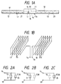
- FIG. 1A illustrates an embodiment of the present invention.
- a case 11 is generally a square or circular one, in which there are housed a radio receiver and a watch, though not shown. Extending from both sides of the case 11 are bands 12 and 13 secured at one end thereto and made to be wound around one's arm by clasps (not shown) on the bands 12 and 13.
- the case 11 and the bands 12 and 13 are made of, for example, synthetic resin in this embodiment.
- a monopole antenna 15 is connected at one end to a feeding point 14 of the radio receiver housed in the case 11 and is exposed at the other end to the outside of the case 11 to form a contact portion 16 for contact with the human body.
- the bottom panel 11a of the case 11 has a small through hole, in which the other end of a conductor forming the monopole antenna 15 is inserted so that the end face of the conductor is flush with the underside of the bottom panel 11a to form the above-mentioned contact portion 16.
- the length L1 of the monopole antenna 15 is selected to be smaller than 0.15 times the working wavelength ⁇ of the receiver built in the case 11.
- the bands 12 and 13 there are embedded helical antennas 17 and 18, respectively.
- the center lines of the helical antennas 17 and 18 extend along the entire lengths of the bands 12 and 13.
- the helical antennas 17 and 18 are rectangular helical windings of conductors as shown on an enlarged scale and the long sides of the rectangles extend widthwise of the bands 12 and 13.
- the helical antenna 17 has its inner end connected to the feeding point 14 and the helical antenna 18 has its inner end connected to a common potential point 19 of the receiver in the case 11.
- the helical antennas 17 and 18 are wound in opposite directions, as viewed from the feeding point 14 and the common potential point 19, respectively.
- each of the helical antennas 17 and 18, that is, the pitch P, the area A surrounded by the conductor as viewed from a direction perpendicular to the helix axis (which area will hereinafter be referred to as a helix area) and the number of turns, are selected such that the helical antennas 17 and 18 substantially resonate, as one antenna, at the wavelength ⁇ when a feeding power source (a load, in practice, because they are connected to the receiver) is connected between the feeding point 14 and the common potential point 19. Further, the pitch P and the helix area A are selected so that P ⁇ 500A/ ⁇ and P > 150A/ ⁇ .
- the human body, and its input impedance Z1 decreases to a value ranging from 150 to 300 ⁇ , whereas the helical antennas 17 and 18 are held close to the human body and their input impedance Z2 becomes higher than 600 ⁇ . That is, the input impedances Z1 and Z2 bear a relation Z1 ⁇ 2Z2, and current flowing across the helical antennas 17 and 18, viewed from the feeding point 14, becomes 1/3 to 1/5 the current flowing across the monopole antenna 15, with the result that the monopole antenna 15 operates as the main antenna, as shown in Fig. 2B, providing a large gain.
- the monopole antenna 15 does not contact the human body and exists merely as a wire shorter than 0.15 ⁇ ; namely, the tip of the monopole antenna 15 is open and its input impedance Z1 is considered to be infinite.
- the input impedance Z2 becomes 20 to 50 ⁇ .
- the monopole antenna 15 is disconnected and only the helical antennas 17 and 18 act as an antenna, obtaining a large gain close to that of a half-wave dipole antenna.
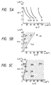
- Fig. 3A shows a monopole antenna with an inner conductor 22 of a coaxial cable 21 projecting out therefrom by a length L1.
- Fig. 3B shows variations caused in the gain of the monopole antenna when the length L1 was varied with a fingertip 23 held in contact with the tip of the inner conductor 22.
- the abscissa represents the length L1 expressed in terms of the working wavelength ⁇ and the ordinate represents the antenna gain G standardized using the antenna gain when the inner conductor 22 is not touched with the fingertip 23. That is, 0 dB is the gain when the inner conductor 22 is not touched with the fingertip 23. It appears from Fig.
- the length L1 of the monopole antenna 15 is therefore selected to be 0.15 ⁇ as mentioned previously.
- the input impedance of this antenna was about 300 ⁇ in absolute value.
- Fig. 5A shows the relationships between the helix area A, the pitch P and the number of turns N (half side of the helical antenna) of each square helical antenna obtained when they resonate at a given wavelength ⁇ .
- the abscissa represents the helix area A/ ⁇
- the ordinate represents the pitch P/ ⁇
- the parameter used is the number of turns N.
- Fig. 5A indicates that when the number of turns N is held constant, the pitch P must be decreased as the helix area A increases to get a resonance, that when the pitch P is held constant, the number of turns N must be decreased as the helix area A increases, and that when the helix area A is held constant, the number of turns N must be decreased as the pitch P increases.
- the geometry of each of the helical antennas 17 and 18, that is, the helix area A, the pitch P and the number of turns N are chosen to satisfy the relationships shown in Fig. 5A so that they resonate at the given frequency.
- Fig. 5B shows the input impedance of each of the square helical antennas in their resonant state.
- the abscissa represents the helix area A/ ⁇ and the ordinate represents the pitch P/ ⁇ , numerical values stated in the graph being the input impedance.
- the numerical value 14.4 is the input impedance when A/ ⁇ is about 40 ⁇ 10 ⁇ 6 and P/ ⁇ is 4 ⁇ 10 ⁇ 3.
- the input impedance is in the range of 20 to 100 ⁇ , even if the antenna is connected directly to the receiver of a standard input impedance (usually 50 ⁇ ), the VSWR (that is, the voltage standing wave ratio) becomes lower than 2 and the gain of the helical antenna during resonance is close to the gain of a half-wave dipole antenna, substantially -2 to -5 dBd (dBd is the unit with the gain of the half-wave dipole antenna assumed to be zero).
- the condition P > 150 A/ ⁇ is used in the present invention.
- Fig. 5C shows the relationship between a maximum value of the absolute value of the input impedance, the helix area A and the pitch P in the case where the square helical antenna is held close to a position substantially in contact with the human body.
- the input impedance becomes higher than about 600 ⁇ , and when the monopole antenna 15 is held in contact with the human body, it performs the function of the main antenna rather than the helical antennas 17 and 18. For this reason, the condition P ⁇ 500 A/ ⁇ is used in the present invention.
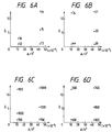
- Fig. 6B also shows that the input impedance remains substantially unchanged, even if the aspect ratio is changed.
- Fig. 6 indicates that the helical antennas 17 and 18 may be square, rectangular, circular, or elliptic in shape.
- Fig. 7 shows the distance L2 (see Fig. 1A) between the helical antenna and the human body in the case where the absolute value of the input impedance is greater than 600 ⁇
- the distance L2 needs to be selected in the ranges of 0 to 0.003 ⁇ , 0.001 to 0.005 ⁇ and 0.002 to 0.005 ⁇ , respectively, regardless of the helix area A.
- the black circles indicate measured points.
- the distance L2 needs to be chosen in the range of 0.0005 to 0.004 ⁇ .
- the aspect ratio ⁇ is equal to or greater than 5.5, it is necessary that the undersides of the bands 12 and 13 which contact the user's arm and the helical antennas 17 and 18 be spaced apart the distance L2 equal to or greater than 0.0005 ⁇ in Fig. 1, for instance.
- the wrist watch type receiver is formed so that when it is carried on the user's arm, a dielectric layer 27 of the 0.0005 ⁇ or more thickness, which may preferably be determined by the conditions shown in Fig. 7, is interposed between the human body and the helical antennas 17 and 18.
- the bands 12 and 13 partly form the interposed layer 27.
- a conductor plate 28 is embedded in or stuck to the underside of the case 11 and the monopole antenna 15 is connected at one end to the conductor plate 28 to form the contact portion 16 for contact with the human body, as shown in Fig. 8A in which the parts corresponding to those in Fig. 1 are identified by the same reference numerals.
- the gain of the monopole antenna 15 can be increased.
- the input impedances when rectangular metal plates measuring 0.01 ⁇ 0.02 ⁇ and 0.02 ⁇ 0.025 ⁇ are used as the metal plate 29, are about 150 ⁇ and about 200 ⁇ , respectively, and they are smaller than 300 ⁇ or so in the case of the metal plate 29 is not used.
- the provision of the conductor plate 28 as shown in Fig. 8A causes an increase in the gain of the monopole antenna 15 and can be used in combination with the helical antennas.
- the bottom panel lla of the case 11 is formed by a metal back cover, to which one end of the monopole antenna is connected so that the back cover acts as plate 28 and forms the contact portion 16.
- the monopole antenna 15 may be connected to the conductor plate 28 at any positions thereon, not always centrally thereof.
- Figs. 8B and 8C illustrate another embodiment of the present invention, in which the parts corresponding to those in Fig. 1 are identified by the same reference numerals.
- This embodiment employs zigzag antennas 31 and 32 in place of the helical antennas 17 and 18.
- the zigzag antenna 31 extends zigzag in the band 12 from one end to the other and its inner end is connected to the feeding point 14.
- the zigzag antenna 32 is also formed in the same manner and its inner end is connected to the common potential point 19.
- Each bent portion of the zigzag antenna 31 and 32 is preferably U-shaped, triangular or meander.
- the configuration of zigzag antennas 31 and 32 is selected so that, viewed from the feeding point 14 and the common potential point 19 when the receiver is placed in the free space apart from the human body, the antennas function as one antenna substantially resonant with the wavelength ⁇ .
- the antennas function as one antenna resonant with the wavelength ⁇ when the antenna width W, the pitch P and the number of turn-down M at one side bear such relationships shown in Fig. 10A.
- the antenna width W of each of the zigzag antennas 31 and 32 is gradually varied, but the same relationship as shown in Fig. 10A exists and the antenna width W, the pitch P and the number of bends M of each of the zigzag antennas 31 and 32 are chosen so that they essentially resonate with a given wavelength ⁇ .
- the antenna width W of each of the zigzag antennas 31 and 32 is selected smaller than 0.003 ⁇ so that the input impedance during resonance in the free space exceeds 20 ⁇ ; by this, the zigzag antennas can be connected directly to a receiver of a standard input impedance.
- Fig. 10B shows the input impedance of the zigzag antenna used for the experiments in Fig. 10A, measured for various values of the antenna width W and the pitch P.
- the antenna width W and the pitch P are selected in the hatched region in which W ⁇ 0.03 ⁇ .
- the pitch P is selected smaller than 0.84W so that when the wrist watch type receiver is carried on the arm, the input impedance of the zigzag antennas 31 and 32 may exceed 600 ⁇ and the monopole antenna 15 mainly functions as an antenna.
- Fig. 10C shows maximum values of the absolute value of the input impedance of the above-said zigzag antenna held substantially in contact with the human body, measured for various values of the antenna width W and the pitch P.
- the input impedance will exceed 600 ⁇ , if the human body and the zigzag antennas 31 and 32 are spaced 0.001 ⁇ or less apart and the pitch P and the antenna width W are within the ranges in which they satisfy the afore-mentioned relationships.
- the monopole antenna 15 when the receiver is carried on the arm, the monopole antenna 15 mainly functions and obtains a high gain and when the receiver is held apart from the arm, the zigzag antennas 31 and 32 serve as an antenna and obtain a high gain, as in the embodiment of Fig. 1. Also in the embodiment of Fig. 8B the contact portion 16 of the monopole antenna 15 may be formed by the afore-mentioned conductor plate 28. In either of the embodiments depicted in Figs.
- the helical antennas 17 and 18 and the zigzag antennas 31 and 32 need not always be embedded in the bands 12 and 13 but may also be provided in contact with the bands 12 and 13 at one side thereof or mounted on the outside of them, and the helical antennas 17 and 18 may also be wound around the bands 12 and 13.
- the exposed helical antennas 17 and 18 and the zigzag antennas 31 and 32 are each coated with an insulating film or formed by a conductor coated with an insulating film.
- the wrist watch type receiver of the present invention when it is carried on the arm, the input impedances of the helical antennas 17 and 18 or the zigzag antennas 31 and 32 rise, the monopole antenna 15 is held in contact with the human body and only this antenna 15 performs the function of an antenna and obtains a high gain.
- the input impedance of the monopole antenna 15 is substantially infinite, the helical antennas 17 and 18 or the zigzag antennas 31 and 32 enter the resonant state, and their input impedance becomes about 20 ⁇ , so that the antennas can be connected to the receiver without using a matching circuit and a high gain can be obtained.
- the operation of the receiver of the present invention is excellent, regardless of whether it is carried on the arm or not.
- the helical antennas 17 and 18 in the Fig. 1 embodiment were 0.16 ⁇ long, the long and short sides of each rectangle defining the helix area were 0.02 and 0.002 ⁇ , respectively, and the number of turns N was 24, the helix area was 34 ⁇ 10 ⁇ 6/ ⁇ and the pitch was 6.3 ⁇ 10 ⁇ 3/ ⁇ , and consequently, the afore-mentioned conditions were satisfied.
- the helical antennas 17 and 18 resonated, and when the receiver was carried on the arm, their input impedance was above 600 ⁇ .
- the length L1 of the monopole antenna 15 was 0.005 ⁇ , the antenna gain was -15 dBd when the receiver was carried on the arm and -5 dBd when the receiver was not on the arm.
- the zigzag antennas 31 and 32 in the Fig. 8B embodiment were each formed by bending, in zigzag, a strip-like conductor of a 5 ⁇ 10 ⁇ 4 ⁇ line width
- the pitch P was 0.0015 ⁇
- the antenna width W was 0.03 ⁇ toward the case 11 and 0.017 ⁇ toward the free end of each band
- the number of bends M of each antenna was 21.5
- the distances from the feeding point 14 and the common potential point 19 to the antennas were each 0.024 ⁇ and the length L1 of the monopole antenna 15 was 0.005 ⁇
- the antenna gain was -15 dBd when the receiver was carried on the arm and -15 dBd when the receiver was not on the arm.
Claims (4)
- Récepteur du type montre-bracelet comprenant :un boîtier (11) ayant un récepteur de radio logé à l'intérieur;une paire de bandes (12, 13) fixées chacune à l'une de ses extrémités à un côté dudit boîtier (11) et pouvant être enroulées autour du bras d'une personne;une première antenne (17) reliée à l'une de ses extrémités à un point d'alimentation (14) dudit récepteur de radio, supportée par l'une desdites bandes (12 , 13) et s'étendant suivant la longueur de celle-ci; etune seconde antenne (18) reliée à l'une de ses extrémités à un point de potentiel commun (19) dudit récepteur de radio, supportée par l'autre desdites bandes (12, 13) et s'étendant suivant la longueur de celle-ci,ledit récepteur étant caractérisé en cequ'il comprend une antenne monopolaire (15) dont une extrémité est reliée audit point d'alimentation (14) dudit récepteur de radio et dont l'autre extrémité est exposée à l'extérieur dudit boîtier (11) pour former une partie de contact (16) pour le contact avec le corps humain, la longueur de ladite antenne monopolaire (15) étant inférieure ou égale à 0,15 λ et non nulle, λ étant la longueur d'onde de la fréquence utilisée par ledit récepteur de radio; et en ceque chacune desdites première et seconde antennes (17, 18) est une antenne hélicoïdale, dont le pas P et la surface d'hélice A sont choisies de façon que 500 A/λ > P > 150 A/λ.
- Récepteur du type montre-bracelet selon la revendication 1, dans lequel une zone qui définit ladite surface d'hélice de chacune desdites première et seconde antennes hélicoïdales (17, 18) est rectangulaire et la longueur du rectangle s'étend suivant la largeur de chacune desdites bandes (12, 13), et dans lequel une couche isolante (27) ayant une épaisseur supérieure ou égale à 0,0005 λ sépare lesdites première et seconde antennes hélicoïdales (17, 18) du corps humain lorsque ledit récepteur du type montre-bracelet est attaché audit bras.
- Récepteur du type montre-bracelet comprenant :un boîtier (11) ayant un récepteur de radio logé à l'intérieur;une paire de bandes (12, 13) fixées chacune à l'une de ses extrémités à un côté dudit boîtier (11) et pouvant être enroulées autour du bras d'une personne;une première antenne en zigzag (32) reliée à l'une de ses extrémités à un point d'alimentation (14) dudit récepteur de radio, supportée par l'une desdites bandes (12, 13) et s'étendant suivant la longueur de celle-ci; etune seconde antenne en zigzag (32) reliée à l'une de ses extrémités à un point de potentiel commun (19) dudit récepteur de radio, supportée par l'autre desdites bandes (12, 13) et s'étendant suivant la longueur de celle-ci, ledit récepteur étant caractérisé en cequ'il comprend une antenne monopolaire (15) dont une extrémité est reliée audit point d'alimentation (14) dudit récepteur de radio et dont l'autre extrémité est exposée à l'extérieur dudit boîtier (11) pour former une partie de contact (16) pour le contact avec le corps humain, la longueur de ladite antenne monopolaire (15) étant inférieure ou égale à 0,15 λ et non nulle, λ étant la longueur d'onde de la fréquence utilisée par ledit récepteur de radio; et en ceque les largeurs W et les pas P d'antenne desdites première et seconde antennes en zigzag (31, 32) sont choisis de façon que W < 0,03 λ et P < 0,84 W.
- Récepteur du type montre-bracelet selon l'une quelconque des revendications 1 à 3, dans lequel ladite partie de contact (16) de ladite antenne monopolaire (15) est formée par une plaque conductrice (28).
Applications Claiming Priority (2)
| Application Number | Priority Date | Filing Date | Title |
|---|---|---|---|
| JP37396/90 | 1990-02-20 | ||
| JP02037396 | 1990-02-20 |
Publications (2)
| Publication Number | Publication Date |
|---|---|
| EP0443491A1 EP0443491A1 (fr) | 1991-08-28 |
| EP0443491B1 true EP0443491B1 (fr) | 1996-05-01 |
Family
ID=12496371
Family Applications (1)
| Application Number | Title | Priority Date | Filing Date |
|---|---|---|---|
| EP91102276A Expired - Lifetime EP0443491B1 (fr) | 1990-02-20 | 1991-02-18 | Récepteur en forme de montre-bracelet |
Country Status (4)
| Country | Link |
|---|---|
| US (1) | US5136303A (fr) |
| EP (1) | EP0443491B1 (fr) |
| JP (1) | JP3055703B2 (fr) |
| DE (1) | DE69119109T2 (fr) |
Cited By (1)
| Publication number | Priority date | Publication date | Assignee | Title |
|---|---|---|---|---|
| WO1998024143A1 (fr) * | 1996-11-29 | 1998-06-04 | Soon Jo Jung | Antennes minces |
Families Citing this family (31)
| Publication number | Priority date | Publication date | Assignee | Title |
|---|---|---|---|---|
| US5589840A (en) * | 1991-11-05 | 1996-12-31 | Seiko Epson Corporation | Wrist-type wireless instrument and antenna apparatus |
| EP0616384B1 (fr) * | 1993-03-17 | 2000-05-31 | Seiko Epson Corporation | Antenne et dispositif incluant une telle antenne |
| US5757326A (en) * | 1993-03-29 | 1998-05-26 | Seiko Epson Corporation | Slot antenna device and wireless apparatus employing the antenna device |
| JP3417083B2 (ja) * | 1994-10-04 | 2003-06-16 | セイコーエプソン株式会社 | 携帯用無線機 |
| US5886669A (en) * | 1995-05-10 | 1999-03-23 | Casio Computer Co., Ltd. | Antenna for use with a portable radio apparatus |
| DE69522668T2 (de) * | 1995-05-17 | 2002-06-20 | Murata Manufacturing Co | Oberflächenmontierbares Antennensystem |
| US5764197A (en) * | 1995-06-20 | 1998-06-09 | Murata Manufacturing Co., Ltd. | Chip antenna |
| JPH0964627A (ja) * | 1995-08-23 | 1997-03-07 | Murata Mfg Co Ltd | 表面実装型アンテナ |
| JPH0974307A (ja) * | 1995-09-05 | 1997-03-18 | Murata Mfg Co Ltd | チップアンテナ |
| JP3289572B2 (ja) * | 1995-09-19 | 2002-06-10 | 株式会社村田製作所 | チップアンテナ |
| US5754143A (en) * | 1996-10-29 | 1998-05-19 | Southwest Research Institute | Switch-tuned meandered-slot antenna |
| US6366250B1 (en) * | 1999-12-09 | 2002-04-02 | Sirf Technology, Inc. | Wrist mounted wireless instrument and antenna apparatus |
| JP3905418B2 (ja) | 2001-05-18 | 2007-04-18 | セイコーインスツル株式会社 | 電源装置および電子機器 |
| US7167140B2 (en) | 2003-07-02 | 2007-01-23 | Nec Tokin Corporation | Coil antenna |
| JP3964401B2 (ja) | 2004-04-27 | 2007-08-22 | Necトーキン株式会社 | アンテナ用コア、コイルアンテナ、時計、携帯電話機、電子装置 |
| DE602004015075D1 (de) * | 2004-04-27 | 2008-08-28 | Nec Tokin Corp | Spulenantenne |
| US7162217B2 (en) | 2004-07-02 | 2007-01-09 | Eta Sa Manufacture Horlogère Suisse | Interconnection circuit between two loop antennas embedded in a wristband of a wrist-carried wireless instrument |
| US7038634B2 (en) * | 2004-07-02 | 2006-05-02 | Eta Sa Manufacture Horlogère Suisse | Optimization of a loop antenna geometry embedded in a wristband portion of a watch |
| EP1612884B1 (fr) * | 2004-07-02 | 2008-10-15 | ETA SA Manufacture Horlogère Suisse | Circuit de connexion entre deux antennes à boucles integrées dans un bracelet d'un instrument sans fils porté au poignet |
| KR100785764B1 (ko) * | 2005-05-11 | 2007-12-18 | 한국전자통신연구원 | 인체 안테나를 이용한 지상파 dmb 수신 장치 및 그 방법 |
| KR20070016545A (ko) * | 2005-08-04 | 2007-02-08 | 삼성전자주식회사 | 휴대용 단말기의 안테나 장치 |
| KR100724133B1 (ko) * | 2005-10-11 | 2007-06-04 | 삼성전자주식회사 | 원격 모니터링을 위한 소형 액세서리 |
| US7663556B2 (en) | 2006-04-03 | 2010-02-16 | Ethertronics, Inc. | Antenna configured for low frequency application |
| US7696932B2 (en) | 2006-04-03 | 2010-04-13 | Ethertronics | Antenna configured for low frequency applications |
| US8121662B2 (en) | 2006-07-28 | 2012-02-21 | Marvell World Trade Ltd. | Virtual FM antenna |
| DE102007037614B4 (de) * | 2007-08-09 | 2014-03-13 | Continental Automotive Gmbh | Mehrteilige Antenne mit zirkularer Polarisation |
| DE102007061305B4 (de) * | 2007-12-19 | 2012-04-26 | Continental Automotive Gmbh | Mehrteilige Antenne mit zirkularer Polarisation und Funkstation |
| JP6104435B2 (ja) * | 2012-07-19 | 2017-03-29 | 日本特殊陶業株式会社 | ガスセンサ |
| US10033092B2 (en) | 2015-07-22 | 2018-07-24 | Futurewei Technologies, Inc. | Apparatus and method for utilizing a component with a helical antenna for communicating RF signals |
| US10615489B2 (en) | 2016-06-08 | 2020-04-07 | Futurewei Technologies, Inc. | Wearable article apparatus and method with multiple antennas |
| CN112882377A (zh) * | 2019-11-29 | 2021-06-01 | RealMe重庆移动通信有限公司 | 穿戴式电子设备 |
Citations (3)
| Publication number | Priority date | Publication date | Assignee | Title |
|---|---|---|---|---|
| JPS55104810U (fr) * | 1979-01-17 | 1980-07-22 | ||
| JPS57132286U (fr) * | 1981-02-12 | 1982-08-18 | ||
| JPS60193773U (ja) * | 1984-05-31 | 1985-12-23 | アルプス電気株式会社 | ヘツドホン装置 |
Family Cites Families (14)
| Publication number | Priority date | Publication date | Assignee | Title |
|---|---|---|---|---|
| US3032651A (en) * | 1957-07-02 | 1962-05-01 | Gisiger-Stahli Josef | Wrist carried radio set |
| US4074282A (en) * | 1976-05-13 | 1978-02-14 | North American Philips Corporation | Radiation-sensitive record with protected sensitive surface |
| JPS5687807A (en) * | 1979-12-18 | 1981-07-16 | Fujitsu Ltd | Detecting method of mark |
| JPS56172006U (fr) * | 1980-05-21 | 1981-12-18 | ||
| EP0100639A3 (fr) * | 1982-08-02 | 1986-03-05 | Shaye Communications Limited | Dispositif de couplage pour aérien |
| JPS6035644U (ja) * | 1983-08-15 | 1985-03-12 | オリエント時計株式会社 | ラジオ受信機 |
| JPH073923B2 (ja) * | 1985-02-06 | 1995-01-18 | 公人 堀江 | バンド型アンテナ装置 |
| JPS61181202A (ja) * | 1985-02-06 | 1986-08-13 | Hitachi Ltd | 静磁表面波装置 |
| GB2201266A (en) * | 1986-12-23 | 1988-08-24 | Upperpace Limited | A radio paging watch |
| JPS63252002A (ja) * | 1987-04-09 | 1988-10-19 | Seiko Epson Corp | 携帯無線器 |
| US4754285A (en) * | 1987-05-01 | 1988-06-28 | Timex Corporation | Expansion band antenna for a wristwatch application |
| US5007105A (en) * | 1987-08-14 | 1991-04-09 | Nec Corporation | Watch type paging receiver |
| FR2621178B1 (fr) * | 1987-09-25 | 1989-12-01 | Alcatel Thomson Radiotelephone | Antenne bracelet pour recepteur radioelectrique integre dans une montre |
| EP0319214A1 (fr) * | 1987-12-04 | 1989-06-07 | AT&T Corp. | Procédé de fabrication des circuits intégrés par dépôt sélectif du tungstène |
-
1991
- 1991-02-12 JP JP03018825A patent/JP3055703B2/ja not_active Expired - Lifetime
- 1991-02-18 DE DE69119109T patent/DE69119109T2/de not_active Expired - Lifetime
- 1991-02-18 EP EP91102276A patent/EP0443491B1/fr not_active Expired - Lifetime
- 1991-02-19 US US07/656,809 patent/US5136303A/en not_active Expired - Lifetime
Patent Citations (3)
| Publication number | Priority date | Publication date | Assignee | Title |
|---|---|---|---|---|
| JPS55104810U (fr) * | 1979-01-17 | 1980-07-22 | ||
| JPS57132286U (fr) * | 1981-02-12 | 1982-08-18 | ||
| JPS60193773U (ja) * | 1984-05-31 | 1985-12-23 | アルプス電気株式会社 | ヘツドホン装置 |
Cited By (1)
| Publication number | Priority date | Publication date | Assignee | Title |
|---|---|---|---|---|
| WO1998024143A1 (fr) * | 1996-11-29 | 1998-06-04 | Soon Jo Jung | Antennes minces |
Also Published As
| Publication number | Publication date |
|---|---|
| JP3055703B2 (ja) | 2000-06-26 |
| JPH04211522A (ja) | 1992-08-03 |
| US5136303A (en) | 1992-08-04 |
| DE69119109D1 (de) | 1996-06-05 |
| DE69119109T2 (de) | 1996-10-24 |
| EP0443491A1 (fr) | 1991-08-28 |
Similar Documents
| Publication | Publication Date | Title |
|---|---|---|
| EP0443491B1 (fr) | Récepteur en forme de montre-bracelet | |
| EP0590534B1 (fr) | Unité radio portable | |
| EP1120855B1 (fr) | Antenne | |
| KR100680711B1 (ko) | 향상된 대역폭을 갖는 소형 안테나와 무선 인식 및 무선센서 트랜스폰더에 이용되는 소형 렉테나 | |
| EP1263081B1 (fr) | Antenne hélicoidale | |
| US5231412A (en) | Sleeved monopole antenna | |
| US6034648A (en) | Broad band antenna | |
| EP1032076B1 (fr) | Dispositif d'antenne et appareil radio l'utilisant | |
| EP1332535B1 (fr) | Dispositif d'antenne | |
| US6396460B2 (en) | Chip antenna | |
| JP2005286895A (ja) | アンテナ装置および携帯無線装置 | |
| US20080122710A1 (en) | Folded dipole loop antenna having matching circuit integrally formed therein | |
| AU2002215265A1 (en) | An antenna device | |
| EP1441415A1 (fr) | Antenne compacte avec charge capacitive en sommet | |
| EP0582423A1 (fr) | Antenne pour appareil radio | |
| JP4413698B2 (ja) | 無給電素子付きリングアンテナ | |
| JP3481537B2 (ja) | 二周波共用ヘリカルアンテナ | |
| JPH08307130A (ja) | 携帯無線機器用アンテナおよび携帯無線機器 | |
| JP3180034B2 (ja) | アンテナ | |
| US4931807A (en) | Non-stationary antenna with sleeve and resonant circuit | |
| JP4460046B2 (ja) | 多周波共用アンテナ | |
| KR20100094190A (ko) | 다중 공진 광대역 안테나 | |
| JP3090242B2 (ja) | 携帯無線機 | |
| WO1998027610A1 (fr) | Connecteur d'antenne | |
| RU2099828C1 (ru) | Плоская резонансная антенна |
Legal Events
| Date | Code | Title | Description |
|---|---|---|---|
| PUAI | Public reference made under article 153(3) epc to a published international application that has entered the european phase |
Free format text: ORIGINAL CODE: 0009012 |
|
| 17P | Request for examination filed |
Effective date: 19910218 |
|
| AK | Designated contracting states |
Kind code of ref document: A1 Designated state(s): DE GB |
|
| 17Q | First examination report despatched |
Effective date: 19931129 |
|
| RAP1 | Party data changed (applicant data changed or rights of an application transferred) |
Owner name: NTT MOBILE COMMUNICATIONS NETWORK INC. Owner name: NIPPON TELEGRAPH AND TELEPHONE CORPORATION |
|
| GRAA | (expected) grant |
Free format text: ORIGINAL CODE: 0009210 |
|
| AK | Designated contracting states |
Kind code of ref document: B1 Designated state(s): DE GB |
|
| RAP1 | Party data changed (applicant data changed or rights of an application transferred) |
Owner name: NTT MOBILE COMMUNICATIONS NETWORK INC. Owner name: NIPPON TELEGRAPH AND TELEPHONE CORPORATION |
|
| REF | Corresponds to: |
Ref document number: 69119109 Country of ref document: DE Date of ref document: 19960605 |
|
| GRAH | Despatch of communication of intention to grant a patent |
Free format text: ORIGINAL CODE: EPIDOS IGRA |
|
| PLBE | No opposition filed within time limit |
Free format text: ORIGINAL CODE: 0009261 |
|
| STAA | Information on the status of an ep patent application or granted ep patent |
Free format text: STATUS: NO OPPOSITION FILED WITHIN TIME LIMIT |
|
| 26N | No opposition filed | ||
| REG | Reference to a national code |
Ref country code: GB Ref legal event code: IF02 |
|
| PGFP | Annual fee paid to national office [announced via postgrant information from national office to epo] |
Ref country code: DE Payment date: 20100226 Year of fee payment: 20 Ref country code: GB Payment date: 20100202 Year of fee payment: 20 |
|
| REG | Reference to a national code |
Ref country code: DE Ref legal event code: R071 Ref document number: 69119109 Country of ref document: DE |
|
| REG | Reference to a national code |
Ref country code: GB Ref legal event code: PE20 Expiry date: 20110217 |
|
| PG25 | Lapsed in a contracting state [announced via postgrant information from national office to epo] |
Ref country code: GB Free format text: LAPSE BECAUSE OF EXPIRATION OF PROTECTION Effective date: 20110217 |
|
| PG25 | Lapsed in a contracting state [announced via postgrant information from national office to epo] |
Ref country code: DE Free format text: LAPSE BECAUSE OF EXPIRATION OF PROTECTION Effective date: 20110218 |