EP0443101A2 - Installation de désossage facilité de parties d'une carcasse, en particulier de quartiers de carcasses bovines - Google Patents
Installation de désossage facilité de parties d'une carcasse, en particulier de quartiers de carcasses bovines Download PDFInfo
- Publication number
- EP0443101A2 EP0443101A2 EP90121726A EP90121726A EP0443101A2 EP 0443101 A2 EP0443101 A2 EP 0443101A2 EP 90121726 A EP90121726 A EP 90121726A EP 90121726 A EP90121726 A EP 90121726A EP 0443101 A2 EP0443101 A2 EP 0443101A2
- Authority
- EP
- European Patent Office
- Prior art keywords
- transport
- plant according
- track section
- section
- transport path
- Prior art date
- Legal status (The legal status is an assumption and is not a legal conclusion. Google has not performed a legal analysis and makes no representation as to the accuracy of the status listed.)
- Withdrawn
Links
Images


Classifications
-
- A—HUMAN NECESSITIES
- A22—BUTCHERING; MEAT TREATMENT; PROCESSING POULTRY OR FISH
- A22B—SLAUGHTERING
- A22B5/00—Accessories for use during or after slaughtering
- A22B5/0017—Apparatus for cutting, dividing or deboning carcasses
- A22B5/0029—Cutting through or detaching portions of a carcass
-
- A—HUMAN NECESSITIES
- A22—BUTCHERING; MEAT TREATMENT; PROCESSING POULTRY OR FISH
- A22B—SLAUGHTERING
- A22B7/00—Slaughterhouse arrangements
- A22B7/001—Conveying arrangements
Definitions
- a relatively short, first transport track section is arranged such that its front end can be lowered in the transport direction.
- a stop is provided at the front end of this pivotable transport track section.
- the propulsion unit extends at a distance parallel to the second transport track section adjoining to the front in the transport direction.
- a first region of a slaughter animal part to be dismantled which is attached to a transport hook on the first transport track section and is fixed by the stop, is thereby held in the back while a second region of the slaughter animal part to be dismantled, which is suspended by a transport hook on the second transport track section, is moved forward by means of the engaging part of the propulsion unit.
- the working disassembler can perform his trigger cuts or disassembly cuts with ease; Due to the pulling action of the device, its cutting area is opened or kept open. The cutting takes place hygienically when the parts of the slaughter animal are hanging.
- the lowerability of the first transport track section has the purpose of being able to lower the first area of the slaughter animal part to such an extent that the two areas of the slaughter animal part can be pulled apart with the device without substantial "misalignment" of the slaughter animal part.
- the working conditions of the cutters working on the known device are not optimal, because the hanging length of the parts of the slaughtered animal varies depending on the size of the slaughtered animal (even if, for example, it is always cattle), because the fore quarters, long hind quarters and short hind quarters of the slaughter animals change are to be disassembled, and because the disassembler has to make his cuts further up and down on the animal part to be disassembled.
- the invention has for its object to make available a system of the type mentioned, which enables the disassembler to work in an ergonomic, optimal height position. This is particularly important because the dismantling of parts of slaughter animals is a physically very strenuous activity and a disassembler performs the better, depending on the beque mer and less tired he can work.
- the entire slaughter animal part can thus be raised or lowered in an optimal height position for the work of the cutting unit, regardless of the length of the respective slaughter animal part. It is possible for the decomposer, for example after having carried out part of his cutting work, to lift the slaughter animal part so that he can again work in a comfortable height position for the rest of his cutting work.
- the device is in principle also suitable for facilitating the dismantling of entire carcasses.
- the main field of application is the dismantling of parts of slaughter animals, in particular fore quarters, long hind quarters (with a piece of spine and a few ribs) and short hind quarters quarters of cattle.
- the system 50 is preferably designed such that the transport path section can be moved both upwards and downwards in comparison to a neutral height position, in which it passes into the subsequent transport path essentially without a change in height.
- the transport track section can only be moved downwards or upwards from this neutral height position.
- the movability is preferably provided in a substantially vertical direction.
- the term "motor" of the propulsion unit is to be understood comprehensively; in principle, it can be implemented by any suitable drive device. Hydraulic or pneumatic cylinder-piston units are mentioned as examples. However, an electric motor is particularly preferred, particularly because of its good controllability.
- the adjustability of the cut-off propulsive force threshold of the propelling unit primarily serves to be able to adjust the propulsive force to the particular meat texture (soft or firm).
- the disassembler 's work is such that, during the Driving force prevails, cuts. If with increasing "spreading" of the first area and the second area of the slaughter animal part, the driving force continues to increase, a state can be repeatedly reached in which the driving unit switches itself off until the cutter has made further cuts and, as a result, continues to spread reduced propulsive force is possible.
- the speed of movement of the engaging part of the propulsion unit is preferably also adjustable.
- Strain gauges and electrical load cells are preferred as sensors of the propulsion unit. Electric load cells are even more special because they are more precise and robust.
- the guidance is preferably carried out with rolling elements on essentially vertical supports.
- Hydraulic and pneumatic cylinder-piston units are suitable for moving the frame and for moving the height of the first transport track section (cf. claims 10 to 12), with pneumatic cylinder-piston units generally being preferred.
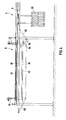
- the dismantling plant which is best manageable in the plan view in FIG. 1, has a first device 2 ("pre-cutting station"), a second device 4 ("pre-dismantling station") and two third devices 6 (“dismantling stations” connected in series) - progressing in the cattle quarter transport direction ”) on.
- a transport path 8 runs through these four devices 2, 4, 6 and is connected at the beginning of the first device 2 'to a leading transport path 10 of the slaughterhouse and behind the fourth device 6 to a leading transport path 12 of the slaughterhouse.
- a relatively short transport path section 14 (referred to in claim 14 as “third transport path section") is connected to the transport path 8 by means of a front and a rear, telescopically variable length, hingedly connected transport path intermediate piece 16.
- the vertical piston rod 18 of a cylinder-piston unit 19 is fastened to the transport track section 14.
- the lower end of the cylinder of the cylinder-piston unit 19 is fastened to a transverse yoke 20 and the upper end of this cylinder is free.
- Two parallel, hydraulic cylinder-piston units 24 act between the transverse yoke 20 and a longitudinal support 22 extending above it.
- the transport path section 14 can be lifted up out of the plane of the transport path 8 by means of the Cylinder-piston units 24, the conveyor track section 14 can be lowered from the plane of the conveyor track 8 downwards, both as indicated by dashed lines in FIG. 5.
- the conveyor track section 14 maintains its orientation parallel to the plane of the conveyor track 8. If a transport hook 26 (cf. FIG. 2), on which a quarter of a cow hangs, is pushed onto the transport track section 14, the quarter of the cow can be raised or lowered by the described height travel, depending on the needs of the disassembler working at this station.
- the second device 4 which can be seen particularly clearly in FIG. 5, on the left, is constructed quite analogously to the first device 2 described.
- an inclined partition 28 is only below the transport path 8 provided, on which the quarter of the beef to be processed is supported on the side facing away from the cutter.
- the inclined cutting wall 28 can be pivoted from a vertical position, in which it is located on the side and allows cattle quarters to be pushed past, and a slightly upwardly tilted position, in which it supports a cattle quarter to be processed, by means of a pneumatic cylinder-piston unit.
- the third device 6 and the fourth device 6 are constructed almost identically, so that they are described only once.
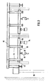
- the device 6 mainly consists of a frame 30 which is essentially rectangular in plan view, four vertical guide beams 32 in the corner regions of the frame 30, and a propulsion unit 34 which is fastened to the frame 30 and extends parallel to a transport track section 36 of the third device 6.
- the frame 30 is essentially in a horizontal plane.
- the frame 30 essentially consists of two side members 38 and four cross members 40 connecting the side members 38.
- the transport track section 36 is fastened to the underside of the frame 30 centrally between the two longitudinal beams 38.
- the cross members 40 are extended beyond the longitudinal members 38 there.
- the propulsion unit 34 is fastened there under the cross members 40 of the frame 30, left or right next to and parallel to the transport track section 36.
- Each guide beam 32 consists of a pair of U-beams which are juxtaposed with their open sides, leaving a gap. At the two ends of both the foremost and the rearmost cross member 40, rollers 42 are attached which engage in the interior of the pair of guide supports 32 in question.
- the guide beams 32 can also be made from a round, square or rectangular tube or another profile.
- the hollow profiles are provided with a slot on one side.
- sliding shoes or sliding sleeves made of metal or plastic can also be used. When using rollers, slide shoes or sliding sleeves arranged on the outside on the guide supports 32, no slots or gaps are required in the guide supports 32.
- a vertical, pneumatic cylinder-piston unit 44 is attached to both the front and rear ends of each longitudinal member 38. Each cylinder-piston unit 44 is fastened at the top to a solid cross member 46 of the device frame.
- the frame 30 can be moved in the vertical direction by means of the cylinder-piston units 44, it being guided through the rollers 42, sliding blocks or sliding sleeves along the guide carrier 32. With the frame 30, the transport track section 36 and the propulsion unit 34 move up and down in translation. The frame 30 can be moved up and down relative to a neutral height position in which the transport track section 36 is aligned with the subsequent transport track 8.
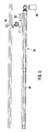
- the propulsion unit 34 mainly has an electric drive geared motor 50 with a straight, elongated housing 48 which is longitudinally slotted on one side, a threaded spindle which is rotatably arranged therein and is not visible in FIG. 3 rotating driving of the threaded spindle, a carriage 52 which can be moved along the housing 48, and an arm 54 which projects transversely to the longitudinal extent of the housing 48 from the carriage 52 as an engagement device on a quarter of a cow to be dismantled.
- One or more traveling nuts sit on the threaded spindle and are connected to the carriage 52, so that the latter is moved in the longitudinal direction when the threaded spindle rotates.
- the arm 54 not shown in FIG. 2, is located somewhat below the pipe section 36.
- a force sensor in particular in the form of a strain gauge or an electrical weighing cell, is arranged on the suspension 56 (FIG. 2) of the propulsion unit 34, so that there is continuously detected how great a longitudinal force the propulsion unit 34 has on the arms 54 that are gripped by the arm 54. exercises the first area of the beef quarter to be dismantled.
- the electric motor 50 is switched off via a circuit (not shown) when this longitudinal force exceeds an adjustable threshold value. When the longitudinal force falls below the set threshold value again, the electric motor 50 is switched on again.
- the third devices 6 are mounted on supports 58 which rest on the slaughterhouse floor. It is alternative possible to design the devices 6 as hanging on the slaughterhouse ceiling or the slaughterhouse walls.
- FIG. 4 shows one of the dismantling stations 6, the jacking unit 34 lying in front of the plane of the drawing not being visible.
- frame 30, cylinder-piston units 44 and transport path section 36 FIG. 4 shows that the transport path section 36 in the transport direction at the front, that is to the left in FIG. 4, via a telescopically variable length, at both ends articulated transport path intermediate piece 60 is connected to the further transport path.
- a rocker 62 is arranged between the rear end of the transport path section 36 and the approaching transport path 8, which is the right end in FIG.
- the frame 30 and thus the transport path section 36 can be raised or lowered relative to the neutral position drawn with a solid line, in which case the transport path intermediate piece 60 and the rocker arm 62 assume oblique positions. Regardless of this height mobility, the rocker 62 can be lowered relative to the conveyor track section 36.
- the height mobility of the rocker 62 shown in FIG. 4 is only one of several possibilities for making the first transport track section movable in height.
- a translatory height mobility of the first transport track section could be provided.
- a further possibility is not to assign the rocker 62 or a first transport track section that is translationally height-adjustable to the frame 30 (whereby it moves up and down together with the frame 30), but rather the rocker 62 or a first transport track section that is translationally height-adjustable a suitable stationary battle hanging up the courtyard.
- the rocker 2 or the translationally vertically movable first transport path section would in principle guide its height movement independently of the height movement of the second transport path section.
- the spinous processes and ribs are then separated at the pre-cutting station 4, for example with the aid of a saw that can be adjusted in depth and is operated by compressed air.
- the lock bone is then released from a piece of meat called "upper shell” at the first dismantling station 6 and a hook is hung in the hole in the lock bone. This hook is pushed onto the rocker 62.
- the propulsion unit 34 is switched on, and its engaging part 54 engages at the top of the leg of the hind quarter, so that leg meat with tubular bones is pulled away from the held lock bone.
- the splitter cuts along the lock bone.
- the lock bone with attached vertebral body hangs on the rocker 62, while the leg meat with tubular bones and roast beef and ribs is separately attached to it the trans hang portbahn section 36.
- the lock bone with adhering vertebral body is discharged at a transport track switch 70 (FIG. 1) and processed further at a bone processing station which is not drawn and described in detail.
- the part of the rear quarter hanging on the second hook is pushed to the second dismantling station 6.
- There a hook is hooked into the leg meat and this is hung on the rocker 62 there.
- the connected tubular bones are pulled forward with the propulsion unit 34 there, while the hook hanging on the rocker 62 is retained.
- the cutter cuts along the long bones.
- the remaining bone components of the rear quarter are caught on the height-adjustable transport track section 36, while the entire meat components of the rear quarter are caught on the hook that hangs on the rocker 62.
- a further variant consists in placing the pre-dismantling station 4 between the two described dismantling stations 6.
- a typical range of the height of the neutral position of the second transport track section 36 is 2.3 to 2.7 m.
- a typical range of the height travel of the second transport track section 36 is 10 to 50 cm either only in one direction from the neutral position or by this amount both up and down from the neutral position.
Landscapes
- Life Sciences & Earth Sciences (AREA)
- Engineering & Computer Science (AREA)
- Food Science & Technology (AREA)
- Processing Of Meat And Fish (AREA)
Applications Claiming Priority (2)
| Application Number | Priority Date | Filing Date | Title |
|---|---|---|---|
| DE3937742 | 1989-11-13 | ||
| DE19893937742 DE3937742A1 (de) | 1989-11-13 | 1989-11-13 | Anlage zum erleichterten zerlegen von schlachttier-teilen, insbesondere rindervierteln |
Publications (2)
| Publication Number | Publication Date |
|---|---|
| EP0443101A2 true EP0443101A2 (fr) | 1991-08-28 |
| EP0443101A3 EP0443101A3 (en) | 1991-10-16 |
Family
ID=6393438
Family Applications (1)
| Application Number | Title | Priority Date | Filing Date |
|---|---|---|---|
| EP19900121726 Withdrawn EP0443101A3 (en) | 1989-11-13 | 1990-11-13 | Means for easy deboning of carcass parts, in particular of bovine quarters |
Country Status (2)
| Country | Link |
|---|---|
| EP (1) | EP0443101A3 (fr) |
| DE (1) | DE3937742A1 (fr) |
Cited By (5)
| Publication number | Priority date | Publication date | Assignee | Title |
|---|---|---|---|---|
| WO1994010847A1 (fr) * | 1992-11-17 | 1994-05-26 | Eez-Away Limited | Desossage de carcasses |
| WO1995002331A1 (fr) * | 1993-07-16 | 1995-01-26 | Norling Lars Erik | Procede et installation permettant de separer un morceau de viande d'une carcasse |
| EP0668018A1 (fr) * | 1994-02-23 | 1995-08-23 | Couedic Madore Equipement (Sarl) | Dispositif pour poste de sciage dans une chaine de découpe primaire d'animaux de boucherie |
| EP0882404A3 (fr) * | 1997-05-19 | 2000-05-10 | MBA S.r.l. | Machine automatique de désossage des jambes de jambon |
| FR2794147A1 (fr) * | 1999-05-28 | 2000-12-01 | Couedic Madore Equipement | Section de voie a niveau variable dans une installation de convoyage aerien |
Families Citing this family (1)
| Publication number | Priority date | Publication date | Assignee | Title |
|---|---|---|---|---|
| EP1591015A4 (fr) * | 2003-02-03 | 2007-08-22 | Maekawa Seisakusho Kk | Systeme de desossement de la viande |
Citations (5)
| Publication number | Priority date | Publication date | Assignee | Title |
|---|---|---|---|---|
| FR2381648A1 (fr) * | 1977-02-23 | 1978-09-22 | Korhonen Kaarlo | Agencement applicable au decoupage de la viande |
| FR2494960A1 (fr) * | 1980-12-02 | 1982-06-04 | Korhonen Kaarlo | Installation pour decouper de la viande |
| AU526861B2 (en) * | 1978-11-07 | 1983-02-03 | Australian Meat and Livestock Corp., The | Slaughtering sequence |
| EP0235001A1 (fr) * | 1986-02-12 | 1987-09-02 | SOCIETE DES VIANDES DU COTENTIN, Société dite: | Installation de désossage suspendu de quartiers de devant de bovins |
| WO1988008250A1 (fr) * | 1987-04-27 | 1988-11-03 | Norling Lars Erik | Procede et dispositif permettant de separer des parties de squelette d'une carcasse |
Family Cites Families (2)
| Publication number | Priority date | Publication date | Assignee | Title |
|---|---|---|---|---|
| DE3011026C2 (de) * | 1980-03-21 | 1986-01-02 | Herta KG Karl Schweisfurth GmbH & Co KG, 4352 Herten | Anlage zum Zerlegen von an einem Hängefördermittel zu einem Fleischauslöseplatz geförderten Schlachttierkörpern |
| FR2554684B1 (fr) * | 1983-11-16 | 1987-07-31 | Aubert George | Dispositif mecanique et automatique d'accrochage des animaux de boucherie apres abattage en abattoirs |
-
1989
- 1989-11-13 DE DE19893937742 patent/DE3937742A1/de active Granted
-
1990
- 1990-11-13 EP EP19900121726 patent/EP0443101A3/de not_active Withdrawn
Patent Citations (5)
| Publication number | Priority date | Publication date | Assignee | Title |
|---|---|---|---|---|
| FR2381648A1 (fr) * | 1977-02-23 | 1978-09-22 | Korhonen Kaarlo | Agencement applicable au decoupage de la viande |
| AU526861B2 (en) * | 1978-11-07 | 1983-02-03 | Australian Meat and Livestock Corp., The | Slaughtering sequence |
| FR2494960A1 (fr) * | 1980-12-02 | 1982-06-04 | Korhonen Kaarlo | Installation pour decouper de la viande |
| EP0235001A1 (fr) * | 1986-02-12 | 1987-09-02 | SOCIETE DES VIANDES DU COTENTIN, Société dite: | Installation de désossage suspendu de quartiers de devant de bovins |
| WO1988008250A1 (fr) * | 1987-04-27 | 1988-11-03 | Norling Lars Erik | Procede et dispositif permettant de separer des parties de squelette d'une carcasse |
Cited By (8)
| Publication number | Priority date | Publication date | Assignee | Title |
|---|---|---|---|---|
| WO1994010847A1 (fr) * | 1992-11-17 | 1994-05-26 | Eez-Away Limited | Desossage de carcasses |
| US5597351A (en) * | 1992-11-17 | 1997-01-28 | Eez-Away Limited | Carcass deboning |
| US5599226A (en) * | 1993-06-16 | 1997-02-04 | Norling; Lars-Erik | Method and plant for separating a part from a carcass |
| WO1995002331A1 (fr) * | 1993-07-16 | 1995-01-26 | Norling Lars Erik | Procede et installation permettant de separer un morceau de viande d'une carcasse |
| EP0668018A1 (fr) * | 1994-02-23 | 1995-08-23 | Couedic Madore Equipement (Sarl) | Dispositif pour poste de sciage dans une chaine de découpe primaire d'animaux de boucherie |
| FR2716340A1 (fr) * | 1994-02-23 | 1995-08-25 | Couedic Madore Equipement | Dispositif pour poste de sciage dans une chaîne de découpage primaire d'animaux de boucherie. |
| EP0882404A3 (fr) * | 1997-05-19 | 2000-05-10 | MBA S.r.l. | Machine automatique de désossage des jambes de jambon |
| FR2794147A1 (fr) * | 1999-05-28 | 2000-12-01 | Couedic Madore Equipement | Section de voie a niveau variable dans une installation de convoyage aerien |
Also Published As
| Publication number | Publication date |
|---|---|
| DE3937742A1 (de) | 1991-05-16 |
| DE3937742C2 (fr) | 1992-07-16 |
| EP0443101A3 (en) | 1991-10-16 |
Similar Documents
| Publication | Publication Date | Title |
|---|---|---|
| DE69630178T2 (de) | Verfahren und Vorrichtung zum Bearbeiten von Schlachtgeflügel | |
| DE3937742C2 (fr) | ||
| DE3529205A1 (de) | Vorrichtung zum abtrennen des kopfes von schlachttierkoerpern, insbesondere rindern | |
| DE2133027A1 (de) | Vorrichtung und Verfahren zum Festhalten eines zu betaeubenden Tieres,insbesondere eines Rindes | |
| DE3011026C2 (de) | Anlage zum Zerlegen von an einem Hängefördermittel zu einem Fleischauslöseplatz geförderten Schlachttierkörpern | |
| DE3327968A1 (de) | Verfahren und vorrichtung zum maschinellen oeffnen auch unterschiedlich grosser fische, insbesondere forellen, und zum entfernen der eingeweide | |
| DE60216971T2 (de) | Vorrichtung und verfahren zum betäuben von schlachttieren | |
| EP0212579B1 (fr) | Dispositif pour ouvrir la poitrine des carcasses, en particulier des bovins ou porcs | |
| EP1763995B1 (fr) | Dispositif et méthode de calibrage d'animaux aquatiques dans une installation d'élevage | |
| DE2902521C3 (de) | Vorrichtung zur Entnahme von Futter aus einem Flachsilo | |
| DE1939046C2 (de) | Vorrichtung zum Zweiteilen von Schlachtviehrümpfen | |
| DE3123439A1 (de) | Vorrichtung zum halbieren von schlachttierkoerpern mittels einer bandsaege | |
| DE69913715T2 (de) | VORRICHTUNG UND VERFAHREN ZUM Auftrennen des Bauches von Schlachtkörpern und deren VERWENDUNG | |
| EP0398219B1 (fr) | Dispositif de transport pas à pas, notamment pour des crochets de transport dans des abattoirs | |
| EP0524647B1 (fr) | Procédé et installation d'abbatage de bovins | |
| EP2986102B1 (fr) | Dispositif de prélèvement de fourrage ensilé | |
| EP0233655A2 (fr) | Dispositif auxiliaire pour le dépouillage des animaux de boucherie | |
| DE3629376C2 (fr) | ||
| DE2050229C3 (de) | Einrichtung zum Längsteilen von Schlachttieren | |
| DE19501413C2 (de) | Verfahren und Vorrichtung zum streßarmen Eintreiben von Schlachttieren, insbesondere Schweinen, in eine Betäubungsstation einer Schlachtanlage | |
| DE2451010C3 (de) | Kombinationsschlachtstraße | |
| DE2050230C3 (de) | Anlage zum Spalten von Schlachttierkörpern längs der Wirbelsäule | |
| DE1921059A1 (de) | Vorrichtung zum Schneiden von Kaesebruch | |
| DE19518336C2 (de) | Vorrichtung zum Betäuben von Schlachttieren | |
| DE2452780A1 (de) | Verfahren und vorrichtung zum zerlegen von geschlachtetem tier |
Legal Events
| Date | Code | Title | Description |
|---|---|---|---|
| PUAI | Public reference made under article 153(3) epc to a published international application that has entered the european phase |
Free format text: ORIGINAL CODE: 0009012 |
|
| PUAL | Search report despatched |
Free format text: ORIGINAL CODE: 0009013 |
|
| AK | Designated contracting states |
Kind code of ref document: A2 Designated state(s): AT CH DE DK LI |
|
| AK | Designated contracting states |
Kind code of ref document: A3 Designated state(s): AT CH DE DK LI |
|
| 17P | Request for examination filed |
Effective date: 19920415 |
|
| STAA | Information on the status of an ep patent application or granted ep patent |
Free format text: STATUS: THE APPLICATION IS DEEMED TO BE WITHDRAWN |
|
| 18D | Application deemed to be withdrawn |
Effective date: 19930602 |