EP0443022B1 - Fahrzeugsitz - Google Patents
Fahrzeugsitz Download PDFInfo
- Publication number
- EP0443022B1 EP0443022B1 EP90915109A EP90915109A EP0443022B1 EP 0443022 B1 EP0443022 B1 EP 0443022B1 EP 90915109 A EP90915109 A EP 90915109A EP 90915109 A EP90915109 A EP 90915109A EP 0443022 B1 EP0443022 B1 EP 0443022B1
- Authority
- EP
- European Patent Office
- Prior art keywords
- air
- vehicle seat
- electrical
- seat according
- set desired
- Prior art date
- Legal status (The legal status is an assumption and is not a legal conclusion. Google has not performed a legal analysis and makes no representation as to the accuracy of the status listed.)
- Expired - Lifetime
Links
- 239000006096 absorbing agent Substances 0.000 claims description 5
- 230000035939 shock Effects 0.000 claims description 5
- 238000006073 displacement reaction Methods 0.000 claims description 2
- 239000000725 suspension Substances 0.000 claims 4
- 230000001133 acceleration Effects 0.000 claims 1
- 230000000306 recurrent effect Effects 0.000 claims 1
- 230000010355 oscillation Effects 0.000 description 14
- 238000009423 ventilation Methods 0.000 description 7
- 238000013022 venting Methods 0.000 description 5
- 230000003068 static effect Effects 0.000 description 2
- 108010076504 Protein Sorting Signals Proteins 0.000 description 1
- 230000004913 activation Effects 0.000 description 1
- 238000010276 construction Methods 0.000 description 1
- 238000001514 detection method Methods 0.000 description 1
- 238000005516 engineering process Methods 0.000 description 1
- 230000001939 inductive effect Effects 0.000 description 1
- 230000005693 optoelectronics Effects 0.000 description 1
Images
Classifications
-
- B—PERFORMING OPERATIONS; TRANSPORTING
- B60—VEHICLES IN GENERAL
- B60N—SEATS SPECIALLY ADAPTED FOR VEHICLES; VEHICLE PASSENGER ACCOMMODATION NOT OTHERWISE PROVIDED FOR
- B60N2/00—Seats specially adapted for vehicles; Arrangement or mounting of seats in vehicles
- B60N2/50—Seat suspension devices
- B60N2/501—Seat suspension devices actively controlled suspension, e.g. electronic control
-
- B—PERFORMING OPERATIONS; TRANSPORTING
- B60—VEHICLES IN GENERAL
- B60N—SEATS SPECIALLY ADAPTED FOR VEHICLES; VEHICLE PASSENGER ACCOMMODATION NOT OTHERWISE PROVIDED FOR
- B60N2/00—Seats specially adapted for vehicles; Arrangement or mounting of seats in vehicles
- B60N2/50—Seat suspension devices
- B60N2/502—Seat suspension devices attached to the base of the seat
-
- B—PERFORMING OPERATIONS; TRANSPORTING
- B60—VEHICLES IN GENERAL
- B60N—SEATS SPECIALLY ADAPTED FOR VEHICLES; VEHICLE PASSENGER ACCOMMODATION NOT OTHERWISE PROVIDED FOR
- B60N2/00—Seats specially adapted for vehicles; Arrangement or mounting of seats in vehicles
- B60N2/50—Seat suspension devices
- B60N2/505—Adjustable suspension including height adjustment
-
- B—PERFORMING OPERATIONS; TRANSPORTING
- B60—VEHICLES IN GENERAL
- B60N—SEATS SPECIALLY ADAPTED FOR VEHICLES; VEHICLE PASSENGER ACCOMMODATION NOT OTHERWISE PROVIDED FOR
- B60N2/00—Seats specially adapted for vehicles; Arrangement or mounting of seats in vehicles
- B60N2/50—Seat suspension devices
- B60N2/506—Seat guided by rods
- B60N2/508—Scissors-like structure
-
- B—PERFORMING OPERATIONS; TRANSPORTING
- B60—VEHICLES IN GENERAL
- B60N—SEATS SPECIALLY ADAPTED FOR VEHICLES; VEHICLE PASSENGER ACCOMMODATION NOT OTHERWISE PROVIDED FOR
- B60N2/00—Seats specially adapted for vehicles; Arrangement or mounting of seats in vehicles
- B60N2/50—Seat suspension devices
- B60N2/52—Seat suspension devices using fluid means
- B60N2/525—Seat suspension devices using fluid means using gas
Definitions
- the invention relates to a vehicle seat with a mechanical vibration system which is cushioned by means of an air spring and with an electronic control which controls air valves for ventilating or venting the air spring as a function of the vibration strokes of the vibration system.
- Electronic controls for air seats are known for example from DE-AS 27 36 242 and from DE-PS 33 12 732. They are each designed for very specific control functions and generate output signals for this purpose, for. B. to switch a servomotor or to monitor the target center position of an air seat by ventilating or venting the air spring. Controls of this type work as a function of the oscillation strokes of the oscillation system, in that two or more measuring sensors usually sense certain positions which are passed by the oscillation systems, ie give them as input signals to the electronic control.
- the object of the invention is to provide an air-sprung vehicle seat with an electronic control which is easy to assemble and which makes it possible to implement and / or change several control functions without problems.
- the vibration system has an oscillation stroke sensor which, during the operating state of the seat, continuously emits an uninterrupted sequence of electrical signals which represent a precise path-analogous and simultaneous electrical image of the vibrations of the vibration system, and in that the electrical vibration image is present at an input of a microprocessor, which compares the vibration image with preset event setpoints in constantly recurring program sequences and, in the event of deviations, generates one or more output signals which at least control the air valves for ventilating and venting the air spring.
- a single sensor mounted on the vibration system is sufficient to meet all the requirements of an electronic seat control. However, it is a prerequisite that this single oscillation stroke sensor permanently emits an uninterrupted sequence of electrical signals that a present a precise path-analog and simultaneous electrical image of the actual vibrations of the vibration system.
- the signal sequences formed by the oscillation stroke sensor can exist as digital value sequences or as electrical analog signals.
- the latter are preferably generated by means of a potentiometer, but can alternatively also, for. B. generated by means of an inductive displacement sensor or an opto-electronic encoder system, as are customary today.
- the generated electrical vibration image of the vibration system is placed at the input of a microprocessor.
- the processor can be located anywhere on the seat or remotely from the seat and does not occupy the confined space within the vibration system, but on the other hand it still has a complete and simultaneous electrical vibration image of the vibration system available at its entrance.
- the processor can use this electrical vibration image to query certain actual vibration values according to its working cycle, that is to say in constantly recurring program sequences, by comparison with preset event target values, the preset or presettable ones according to a particular embodiment of the invention Event setpoints are changeable.
- This is a major advantage, because now any number can Actual event values of the vibrations of the vibration system are recorded without the mechanical arrangement or mechanical change or the adjustment of individual sensors on the vibration system being required for this purpose.
- the vibration system remains free from a multiple arrangement of individual sensors, as was previously known in electronic controls for the detection of various distinguishable input signals.
- the seat control according to the invention is correspondingly simple and easy to adapt to the respective seat type or the respective vibration system.
- the sub-claims 7 and 8 show expedient embodiments of the invention for controlling controllable shock absorbers.
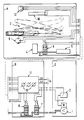
- Shown as units are a seat unit A, a control module B and a compressor part C.
- the vibration system of the seat is shown symbolically within the seat unit A and in the form of a dash-dotted line Scissor link vibration system 3, as is well known in itself.
- the air spring 4 built into the vibration system in a specific embodiment is symbolically shown below the vibration system for better clarity.
- the seat is also equipped with an additional air volume 5 which can be switched on or off from the air volume of the air spring 4 by means of the electromagnetically actuated valve 6.
- the air spring itself is aerated or vented via the ventilation valve 7 and the ventilation valve 8.
- the ventilation valve 7 is switched together with the relay 2 for controlling the compressor 1.
- the oscillation system has an oscillation stroke sensor in the form of a potentiometer 9, which can be mounted in the simplest way between two parts of the scissor link oscillation system 3 that move relative to one another, so that an accurate path-analogous and simultaneous electrical image of the oscillation strokes of the oscillation system is produced .
- the processor in the control module C is first activated by means of a seat contact switch 10.
- the operating status is displayed.
- the path-analog electrical vibration image of the vibration system sensed by means of the potentiometer 9 is permanently present at an input of the processor 11.
- the processor is able to compare the electrical vibration image with preset target values in continuously recurring program sequences.
- the static target center position of the seat is queried. This can be preset using the potentiometer 12, which is easily accessible on the seat.
- the processor 11 In the event of the initially expected deviation, the processor 11 generates an output signal for switching on the compressor 1 and for simultaneously opening the ventilation valve 7. The seat then moves into its static target central position.
- setpoint values which can be set by means of the potentiometer 13, are used to monitor the vibration behavior of the seat in the operating state and to generate output signals in the event of deviations by means of the processor 11, which the ventilation valve 8 and the ventilation valve 7 of the air spring and / or the valve 6 for control the switching on or off of the additional air volume 5.
Landscapes
- Engineering & Computer Science (AREA)
- Aviation & Aerospace Engineering (AREA)
- Transportation (AREA)
- Mechanical Engineering (AREA)
- Seats For Vehicles (AREA)
- Vehicle Body Suspensions (AREA)
- Vehicle Waterproofing, Decoration, And Sanitation Devices (AREA)
- Vibration Prevention Devices (AREA)
- Chair Legs, Seat Parts, And Backrests (AREA)
- Pharmaceuticals Containing Other Organic And Inorganic Compounds (AREA)
- Liquid Crystal (AREA)
- Non-Silver Salt Photosensitive Materials And Non-Silver Salt Photography (AREA)
Applications Claiming Priority (3)
| Application Number | Priority Date | Filing Date | Title |
|---|---|---|---|
| DE3930612A DE3930612A1 (de) | 1989-09-13 | 1989-09-13 | Fahrzeugsitz |
| DE3930612 | 1989-09-13 | ||
| PCT/EP1990/001491 WO1991004168A1 (de) | 1989-09-13 | 1990-09-06 | Fahrzeugsitz |
Publications (2)
| Publication Number | Publication Date |
|---|---|
| EP0443022A1 EP0443022A1 (de) | 1991-08-28 |
| EP0443022B1 true EP0443022B1 (de) | 1995-11-15 |
Family
ID=6389361
Family Applications (1)
| Application Number | Title | Priority Date | Filing Date |
|---|---|---|---|
| EP90915109A Expired - Lifetime EP0443022B1 (de) | 1989-09-13 | 1990-09-06 | Fahrzeugsitz |
Country Status (15)
| Country | Link |
|---|---|
| US (1) | US5272633A (cs) |
| EP (1) | EP0443022B1 (cs) |
| JP (1) | JPH04503343A (cs) |
| AT (1) | ATE130256T1 (cs) |
| AU (1) | AU629995B2 (cs) |
| BR (1) | BR9006915A (cs) |
| CA (1) | CA2041645C (cs) |
| CS (1) | CS444490A3 (cs) |
| DE (2) | DE3930612A1 (cs) |
| ES (1) | ES2085915T3 (cs) |
| RU (1) | RU2062717C1 (cs) |
| TR (1) | TR24755A (cs) |
| WO (1) | WO1991004168A1 (cs) |
| YU (1) | YU172590A (cs) |
| ZA (1) | ZA907253B (cs) |
Cited By (1)
| Publication number | Priority date | Publication date | Assignee | Title |
|---|---|---|---|---|
| DE102006015890A1 (de) * | 2006-04-05 | 2007-10-18 | Bayerische Motoren Werke Ag | Fahrzeugsitzsystem |
Families Citing this family (31)
| Publication number | Priority date | Publication date | Assignee | Title |
|---|---|---|---|---|
| DE4116483A1 (de) * | 1991-05-21 | 1992-11-26 | Keiper Recaro Gmbh Co | Fahrzeugsitz, insbesondere nutzfahrzeugsitz |
| US5169112A (en) * | 1991-08-26 | 1992-12-08 | Milsco Manufacturing Company | Electronic suspension vehicle seat |
| DE4137509C1 (cs) * | 1991-11-14 | 1993-01-21 | Siemens Ag, 8000 Muenchen, De | |
| JP3131295B2 (ja) * | 1992-08-06 | 2001-01-31 | 本田技研工業株式会社 | ロードシミュレーション装置 |
| DE4228061C1 (de) * | 1992-08-24 | 1994-02-03 | Keiper Recaro Gmbh Co | Regelsystem für den Schwingungsdämpfer eines Fahrzeugsitzes, insbesondere eines Nutzfahrzeugsitzes |
| DE4339674C2 (de) * | 1993-11-22 | 2002-11-28 | Keiper Recaro Gmbh Co | System zur Einstellung der Schwingungsdämpfung für einen Fahrzeugsitz, insbesondere Nutzfahrzeugsitz |
| US5536059A (en) * | 1994-11-04 | 1996-07-16 | University Of Illinois | Seat suspension system using human body responses |
| KR970036611A (ko) * | 1995-12-27 | 1997-07-22 | 전성원 | 차량의 시트 높이 조절장치 |
| DE19624587A1 (de) * | 1996-06-20 | 1998-01-22 | Lear Corp | Sitz |
| DE19628974C1 (de) * | 1996-07-18 | 1997-11-20 | Leica Mikroskopie & Syst | Einrichtung zur Schwingungsisolierung |
| AT404815B (de) * | 1996-08-16 | 1999-03-25 | Gerald Ing Christ | Elektronisch gesteuerter fahrersitz |
| WO2002096697A2 (en) * | 2001-05-30 | 2002-12-05 | National Seating Company | Truck seat height positioning system |
| RU2233751C1 (ru) * | 2003-10-09 | 2004-08-10 | Общество с ограниченной ответственностью "Витафон" | Устройство амортизации ударных и вибрационных воздействий |
| RU2266831C1 (ru) * | 2004-06-30 | 2005-12-27 | Кочетов Олег Савельевич | Пневматическая подвеска сиденья оператора |
| RU2266830C1 (ru) * | 2004-06-30 | 2005-12-27 | Кочетов Олег Савельевич | Пневматическая подвеска сиденья самоходного транспортного средства |
| RU2281863C2 (ru) * | 2004-10-15 | 2006-08-20 | Ооо Вибрис-Мм | Подвеска сиденья транспортного средства |
| RU2270108C1 (ru) * | 2004-12-02 | 2006-02-20 | Олег Савельевич Кочетов | Сиденье оператора самоходной сельскохозяйственной техники |
| RU2266832C1 (ru) * | 2004-12-02 | 2005-12-27 | Кочетов Олег Савельевич | Сиденье водителя самоходной сельскохозяйственной техники |
| DE102006004071A1 (de) * | 2006-01-28 | 2007-08-02 | Recaro Aircraft Seating Gmbh & Co. Kg | Sitzpneumatikvorrichtung |
| DE102012020855A1 (de) * | 2012-10-24 | 2014-04-24 | GM Global Technology Operations LLC (n. d. Gesetzen des Staates Delaware) | Verfahren zum Anpassen einer Einstellung eines Fahrzeugsitzes und Fahrzeug mit zu-mindest einem Fahrzeugsitz |
| DE102012224449A1 (de) * | 2012-12-27 | 2014-07-03 | Robert Bosch Gmbh | Sitzvorrichtung |
| DE102013110370B4 (de) | 2013-06-04 | 2014-12-11 | Grammer Ag | Fahrzeugsitz |
| DE102013106709A1 (de) * | 2013-06-26 | 2014-12-31 | Grammer Ag | Vorrichtung mit einem Federungssystem |
| DE102013110923B4 (de) | 2013-10-01 | 2019-07-04 | Grammer Ag | Fahrzeugsitz oder Fahrzeugkabine mit einer Federungseinrichtung und Nutzkraftfahrzeug |
| DE102013110919B4 (de) | 2013-10-01 | 2018-08-02 | Grammer Ag | Stoßdämpfer |
| DE102013110920B4 (de) | 2013-10-01 | 2018-08-16 | Grammer Ag | Fahrzeugsitz mit kraftgesteuertem Dämpfer (2-Rohr-Dämpfer) |
| DE102013110924B4 (de) | 2013-10-01 | 2018-02-08 | Grammer Ag | Fahrzeug mit kraftgesteuertem Dämpfer mit Regelventil |
| DE102013021561B4 (de) | 2013-12-16 | 2020-09-03 | Grammer Ag | Fahrzeugsitz mit einer horizontal beweglichen Sitzfläche zum Aufnehmen einer Person |
| RU177004U1 (ru) * | 2017-07-18 | 2018-02-06 | Федеральное государственное бюджетное образовательное учреждение высшего образования "Волгоградский государственный технический университет" (ВолгГТУ) | Подвеска сиденья транспортного средства |
| US10988060B2 (en) | 2017-12-27 | 2021-04-27 | Ergoair, Inc. | Pneumatic seat support |
| JP7824855B2 (ja) * | 2022-10-11 | 2026-03-05 | 日本発條株式会社 | 車両用シート |
Family Cites Families (13)
| Publication number | Priority date | Publication date | Assignee | Title |
|---|---|---|---|---|
| DE2736242C3 (de) * | 1977-08-11 | 1980-11-27 | Fa. Willibald Grammer, 8450 Amberg | Fahrzeugsitz |
| GB1601370A (en) * | 1977-11-29 | 1981-10-28 | Uop Inc | Vehicle seats |
| JPS54102734A (en) * | 1978-01-30 | 1979-08-13 | Nissan Motor Co Ltd | Device for automatically selecting driving position |
| US4463426A (en) * | 1979-10-12 | 1984-07-31 | International Telephone And Telegraph Corporation | Automatic position control for a vehicle seat |
| JPS56138024A (en) * | 1980-03-31 | 1981-10-28 | Aisin Seiki Co Ltd | Driver's seat |
| DE3312732A1 (de) * | 1983-04-07 | 1984-10-11 | Gebr. Isringhausen, 4920 Lemgo | Verfahren zur ueberwachung der soll-mittellage von luftsitzen |
| US4812838A (en) * | 1984-08-03 | 1989-03-14 | Nippondenso Co., Ltd. | Vehicle seat drive control device |
| DE3608818A1 (de) * | 1985-03-18 | 1986-09-18 | Ikeda Bussan Co | Vorrichtung zur regelung der sitzstellung bei fahrzeugen |
| DE3518382C1 (de) * | 1985-05-22 | 1986-12-04 | Boge Gmbh, 5208 Eitorf | Vorrichtung zur Messung der Beschleunigung von Fahrzeugteilen |
| US4730541A (en) * | 1986-06-03 | 1988-03-15 | Technical Manufacturing Corporation | Non contacting electro-pneumatic servo for vibration isolation |
| JPH0518200Y2 (cs) * | 1987-05-22 | 1993-05-14 | ||
| US4845620A (en) * | 1987-12-22 | 1989-07-04 | United Technologies Automotive, Inc. | Control arrangement for vehicle memory seat |
| US5136221A (en) * | 1991-04-16 | 1992-08-04 | Tachi-S Co. Ltd | Method and device for controlling a powered automotive seat of rotatable type |
-
1989
- 1989-09-13 DE DE3930612A patent/DE3930612A1/de active Granted
-
1990
- 1990-09-06 RU SU904895434A patent/RU2062717C1/ru active
- 1990-09-06 JP JP2513892A patent/JPH04503343A/ja active Pending
- 1990-09-06 WO PCT/EP1990/001491 patent/WO1991004168A1/de not_active Ceased
- 1990-09-06 AT AT90915109T patent/ATE130256T1/de not_active IP Right Cessation
- 1990-09-06 US US07/690,963 patent/US5272633A/en not_active Expired - Lifetime
- 1990-09-06 AU AU65048/90A patent/AU629995B2/en not_active Ceased
- 1990-09-06 DE DE59009884T patent/DE59009884D1/de not_active Expired - Fee Related
- 1990-09-06 EP EP90915109A patent/EP0443022B1/de not_active Expired - Lifetime
- 1990-09-06 ES ES90915109T patent/ES2085915T3/es not_active Expired - Lifetime
- 1990-09-06 BR BR909006915A patent/BR9006915A/pt not_active IP Right Cessation
- 1990-09-06 CA CA002041645A patent/CA2041645C/en not_active Expired - Fee Related
- 1990-09-12 ZA ZA907253A patent/ZA907253B/xx unknown
- 1990-09-12 CS CS904444A patent/CS444490A3/cs unknown
- 1990-09-12 YU YU172590A patent/YU172590A/sh unknown
- 1990-09-26 TR TR90/0868A patent/TR24755A/xx unknown
Cited By (1)
| Publication number | Priority date | Publication date | Assignee | Title |
|---|---|---|---|---|
| DE102006015890A1 (de) * | 2006-04-05 | 2007-10-18 | Bayerische Motoren Werke Ag | Fahrzeugsitzsystem |
Also Published As
| Publication number | Publication date |
|---|---|
| YU172590A (sh) | 1994-09-09 |
| DE59009884D1 (de) | 1995-12-21 |
| CA2041645C (en) | 2001-01-02 |
| ATE130256T1 (de) | 1995-12-15 |
| DE3930612C2 (cs) | 1992-07-02 |
| AU629995B2 (en) | 1992-10-15 |
| WO1991004168A1 (de) | 1991-04-04 |
| AU6504890A (en) | 1991-04-18 |
| CA2041645A1 (en) | 1991-03-14 |
| US5272633A (en) | 1993-12-21 |
| TR24755A (tr) | 1992-05-01 |
| ZA907253B (en) | 1991-06-26 |
| JPH04503343A (ja) | 1992-06-18 |
| BR9006915A (pt) | 1991-12-10 |
| RU2062717C1 (ru) | 1996-06-27 |
| ES2085915T3 (es) | 1996-06-16 |
| CS444490A3 (en) | 1992-02-19 |
| EP0443022A1 (de) | 1991-08-28 |
| DE3930612A1 (de) | 1991-03-21 |
Similar Documents
| Publication | Publication Date | Title |
|---|---|---|
| EP0443022B1 (de) | Fahrzeugsitz | |
| EP1253321A2 (de) | Verfahren zur Steuerung eines Kompressors | |
| EP1122140B1 (de) | Druckluftversorgungseinrichtung für Fahrzeug-Druckluftanlagen | |
| EP1204009A2 (de) | Verfahren zum Betrieb einer Bewegungseinheit | |
| DE4342252A1 (de) | Verfahren zum Regeln des Betriebs eines eine Wiederholungsarbeit ausführenden Baggers | |
| DE3919438A1 (de) | Druckluftbetaetigbare einrichtung mit einem zwischen einer druckmittelquelle und verbrauchern befindlichem lufttrockner | |
| DE10222890B4 (de) | Elektrische Einrichtung für die Ansteuerung eines Mehrwegeventils mit einer Verschleißzustandserkennung | |
| EP2005009A1 (de) | Vorrichtung zur überwachung und/oder regelung der bewegung einer fluidischen komponente in einem fluidischen system | |
| DE69402974T2 (de) | Steuereinrichtung für eine glasformmaschine | |
| DE10041109B4 (de) | System und Verfahren zum Bedienen und Beobachten insbesondere eines Automatisierungssystems mit mobiler Bedienvorrichtung | |
| WO2019052752A1 (de) | Verfahren und bewegungsvorrichtung zum bewegen zumindest eines teils einer manuell bedienbaren bedieneinrichtung zum bedienen einer funktion eines fahrzeugs und bewegungssystem mit einer bewegungsvorrichtung und einer bedieneinrichtung | |
| DE2736603B2 (de) | Reifendruckregelanlage | |
| DE69819796T2 (de) | Ventilantrieb mit Überwachung der Funktionsfähigkeit | |
| DE102015210716B4 (de) | Positionssensor sowie Verfahren zum Betreiben eines Positionssensors | |
| DE19911320A1 (de) | Schaltschranküberwachungseinrichtung | |
| EP0147480A1 (de) | Einrichtung zur Ermittlung von Soll-Werten für den Werkstücktransport einer Mehrstufenpresse | |
| DE10326247B4 (de) | Koordinatenmessmaschine | |
| US4080759A (en) | Grinding machine | |
| DE69420598T2 (de) | Glasspeisevorrichtung mit mehreren Öffnungen | |
| DE19861222B4 (de) | Druckluftversorgungseinrichtung für Fahrzeug-Druckluftanlagen und Verfahren zum Energiesparen bei Druckluftaufbereitungsanlagen | |
| DE4136261A1 (de) | Verfahren und vorrichtung zur betriebsmaessigen beeinflussung von daempfungsbaugruppen eines fahrzeugs | |
| DE3814181A1 (de) | Schwingungsdaempfungssystem fuer maschinentische | |
| DE102020113416B4 (de) | Handhabungsvorrichtung und Verfahren zum Einstellen des Anschlagverhaltens eines Stellglieds der Handhabungsvorrichtung | |
| DE102015224996B4 (de) | Fahrzeug mit Anhänger mit Aufhängungssystem | |
| DE102004046671B3 (de) | Verfahren zum Betreiben einer Steuerungseinrichtung eines Fahrzeuges und Verwendung eines solchen Verfahrens |
Legal Events
| Date | Code | Title | Description |
|---|---|---|---|
| PUAI | Public reference made under article 153(3) epc to a published international application that has entered the european phase |
Free format text: ORIGINAL CODE: 0009012 |
|
| AK | Designated contracting states |
Kind code of ref document: A1 Designated state(s): AT BE DE ES FR GB IT SE |
|
| 17P | Request for examination filed |
Effective date: 19910829 |
|
| 17Q | First examination report despatched |
Effective date: 19920922 |
|
| GRAA | (expected) grant |
Free format text: ORIGINAL CODE: 0009210 |
|
| AK | Designated contracting states |
Kind code of ref document: B1 Designated state(s): AT BE DE ES FR GB IT SE |
|
| REF | Corresponds to: |
Ref document number: 130256 Country of ref document: AT Date of ref document: 19951215 Kind code of ref document: T |
|
| REF | Corresponds to: |
Ref document number: 59009884 Country of ref document: DE Date of ref document: 19951221 |
|
| ITF | It: translation for a ep patent filed | ||
| GBT | Gb: translation of ep patent filed (gb section 77(6)(a)/1977) |
Effective date: 19960217 |
|
| ET | Fr: translation filed | ||
| RAP2 | Party data changed (patent owner data changed or rights of a patent transferred) |
Owner name: GEBR. ISRINGHAUSEN GMBH & CO. KG |
|
| REG | Reference to a national code |
Ref country code: ES Ref legal event code: FG2A Ref document number: 2085915 Country of ref document: ES Kind code of ref document: T3 |
|
| ITPR | It: changes in ownership of a european patent |
Owner name: CAMBIO RAG.SOCIALE;GEBER ISRINGHAUSEN GMBH & CO |
|
| PLBE | No opposition filed within time limit |
Free format text: ORIGINAL CODE: 0009261 |
|
| STAA | Information on the status of an ep patent application or granted ep patent |
Free format text: STATUS: NO OPPOSITION FILED WITHIN TIME LIMIT |
|
| 26N | No opposition filed | ||
| PGFP | Annual fee paid to national office [announced via postgrant information from national office to epo] |
Ref country code: GB Payment date: 20010802 Year of fee payment: 12 |
|
| PGFP | Annual fee paid to national office [announced via postgrant information from national office to epo] |
Ref country code: SE Payment date: 20010806 Year of fee payment: 12 |
|
| PGFP | Annual fee paid to national office [announced via postgrant information from national office to epo] |
Ref country code: BE Payment date: 20010814 Year of fee payment: 12 |
|
| PGFP | Annual fee paid to national office [announced via postgrant information from national office to epo] |
Ref country code: FR Payment date: 20010924 Year of fee payment: 12 |
|
| PGFP | Annual fee paid to national office [announced via postgrant information from national office to epo] |
Ref country code: AT Payment date: 20010930 Year of fee payment: 12 |
|
| REG | Reference to a national code |
Ref country code: GB Ref legal event code: IF02 |
|
| PGFP | Annual fee paid to national office [announced via postgrant information from national office to epo] |
Ref country code: ES Payment date: 20020905 Year of fee payment: 13 |
|
| PG25 | Lapsed in a contracting state [announced via postgrant information from national office to epo] |
Ref country code: GB Free format text: LAPSE BECAUSE OF NON-PAYMENT OF DUE FEES Effective date: 20020906 Ref country code: AT Free format text: LAPSE BECAUSE OF NON-PAYMENT OF DUE FEES Effective date: 20020906 |
|
| PG25 | Lapsed in a contracting state [announced via postgrant information from national office to epo] |
Ref country code: SE Free format text: LAPSE BECAUSE OF NON-PAYMENT OF DUE FEES Effective date: 20020907 |
|
| PG25 | Lapsed in a contracting state [announced via postgrant information from national office to epo] |
Ref country code: BE Free format text: LAPSE BECAUSE OF NON-PAYMENT OF DUE FEES Effective date: 20020930 |
|
| BERE | Be: lapsed |
Owner name: GEBR. *ISRINGHAUSEN G.M.B.H. & CO. Effective date: 20020930 |
|
| GBPC | Gb: european patent ceased through non-payment of renewal fee |
Effective date: 20020906 |
|
| EUG | Se: european patent has lapsed | ||
| PG25 | Lapsed in a contracting state [announced via postgrant information from national office to epo] |
Ref country code: FR Free format text: LAPSE BECAUSE OF NON-PAYMENT OF DUE FEES Effective date: 20030603 |
|
| REG | Reference to a national code |
Ref country code: FR Ref legal event code: ST |
|
| PG25 | Lapsed in a contracting state [announced via postgrant information from national office to epo] |
Ref country code: ES Free format text: LAPSE BECAUSE OF NON-PAYMENT OF DUE FEES Effective date: 20030908 |
|
| REG | Reference to a national code |
Ref country code: ES Ref legal event code: FD2A Effective date: 20030908 |
|
| PGFP | Annual fee paid to national office [announced via postgrant information from national office to epo] |
Ref country code: DE Payment date: 20050902 Year of fee payment: 16 |
|
| PG25 | Lapsed in a contracting state [announced via postgrant information from national office to epo] |
Ref country code: IT Free format text: LAPSE BECAUSE OF NON-PAYMENT OF DUE FEES Effective date: 20050906 |
|
| PG25 | Lapsed in a contracting state [announced via postgrant information from national office to epo] |
Ref country code: DE Free format text: LAPSE BECAUSE OF NON-PAYMENT OF DUE FEES Effective date: 20070403 |