EP0442512A2 - Magnetkopfvorrichtung für magnetische Bänder - Google Patents
Magnetkopfvorrichtung für magnetische Bänder Download PDFInfo
- Publication number
- EP0442512A2 EP0442512A2 EP91102125A EP91102125A EP0442512A2 EP 0442512 A2 EP0442512 A2 EP 0442512A2 EP 91102125 A EP91102125 A EP 91102125A EP 91102125 A EP91102125 A EP 91102125A EP 0442512 A2 EP0442512 A2 EP 0442512A2
- Authority
- EP
- European Patent Office
- Prior art keywords
- tape
- magnetic head
- magnetic
- head device
- guide
- Prior art date
- Legal status (The legal status is an assumption and is not a legal conclusion. Google has not performed a legal analysis and makes no representation as to the accuracy of the status listed.)
- Granted
Links
Images


Classifications
-
- G—PHYSICS
- G11—INFORMATION STORAGE
- G11B—INFORMATION STORAGE BASED ON RELATIVE MOVEMENT BETWEEN RECORD CARRIER AND TRANSDUCER
- G11B15/00—Driving, starting or stopping record carriers of filamentary or web form; Driving both such record carriers and heads; Guiding such record carriers or containers therefor; Control thereof; Control of operating function
- G11B15/60—Guiding record carrier
Definitions
- the present invention relates to a magnetic head device having a magnetic head used for reading and recording signals on a magnetic tape in a cassette recorder.
- the position of the magnetic head can be adjusted so that the gap is located in place for the magnetic tape.
- FIGs. 9 and 10 show an example of the conventional magnetic head.
- a magnetic head 1 has a pair of inside tape guides 2 secured thereto at opposite sides of the head.
- a pair of outside tape guides 7 are mounted on a base 5 for the magnetic head 1. Both the tape guides 2 and 7 have guide grooves 2a and 7a, respectively.
- the magnetic head 1 is mounted on a supporting plate 3 which is held on the base 5 by springs 4 in a floating state. The angular position of the head 1 with respect to a magnetic tape 8 is adjusted by rotating a screw 6 screwed in the base passing through the coil of the spring 4.
- the magnetic tape 8 is guided by the guide grooves 2a and 7a so as to pass a gap 1a of the head 1, making a right angle with a center line of the gap 1a.
- the guide grooves 2a and 7a cannot be aligned exactly because of manufacturing tolerances of the parts.
- the angle of the magnetic head 1 is adjusted by screws 6, it is difficult to finely adjust the angle.
- the angle may change with the time. Even if the angle is exact when the tape runs in the one direction, the effect may occur that the angle deviates when running in the reverse direction.
- Japanese Utility Model Laid Open 60-77006 discloses a magnetic head in which a pair of auxiliary tape guides are made of plastic and integral with each other. However, the angle of the magnetic head must be adjusted by rotating screws.
- the object of the present invention is to provide a magnetic head in which tape guides are made integral with a supporting plate, so that the magnetic tape can be passed through a gap of the magnetic head, making a right angle with the gap, and hence angle adjustment is not necessary, thereby simplifying the assembling of the cassette recorder.
- a magnetic head device comprising a supporting member made of synthetic resin and having tape guides integrally formed thereon, a magnetic head secured to the supporting member, each of the tape guides having a guide groove defined by opposite walls for guiding a magnetic tape passing the magnetic head.
- the opposite walls comprise a perpendicular wall with respect to a bottom of the guide groove, and an inclined wall.
- the bottom of the guide groove has a curved shape in section, which is inclined with respects to a running direction of the magnetic tape.
- the tape guides comprise a pair of inside tape guides and a pair of outside tape guides, which are disposed on opposite sides of the magnetic head.
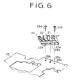
- a head supporting member 23 made of plastic and having an opening 23s for mounting a magnetic head 21.
- a pair of inside tape guides 22 are integrally formed on the head supporting member 23 at opposite sides of the opening 23s, and a pair of outside tape guide 27 are integrally formed on the supporting member 23 at opposite end portions thereof.
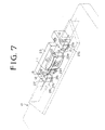
- the tape guide 27 is inserted into an opening 12 of a cassette half 10 as shown in Fig. 7.
- a width A of the guide groove 27a of the tape guide 27 is finished with high accuracy.
- the width A for a magnetic tape 28 having a standard width of 3,76 to 3,81 mm is 3,79 to 3,83 mm. If the width A is smaller than 3,79, edges of the magnetic tape may be curled by walls of the guide groove, which will cause damage of the tape. If the width exceeds 3,83 mm, the tape cannot be guided properly so that the tape may be inclined with respect to a center line of a gap of the magnetic head. Such an inclination of the tape causes a reduction of the output of the magnetic head.
- the output reduction can be expressed as follows.
- Fig. 3 shows the relationship between the output reduction and the gap ⁇ L. If a maximum allowable output reduction is -5 dB at 10 kHz, the gap ⁇ L is 0,12 mm. A preferable output reduction in consideration of quantity production is -1,5 dB. Therefore the gap ⁇ L is 0,07 mm. Accordingly, a maximum width A of the guide groove is 3,83 mm.
- the guide groove 27a in the longitudinal direction of the tape 28 increases, the more running stability of the tape is ensured.
- the guide groove has a length approximately equal to the width of the opening 12 of the cassette half 10 as shown in Fig. 7.
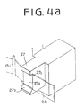
- opposite walls 27c defining the guide groove 27a are perpendicular to the bottom of the groove as shown in Fig. 7, one of the walls 27c may be inclined as shown in Fig. 4a by reference 27b.
- the inclined wall 27b causes the magnetic tape to urge to the perpendicular wall 27c, thereby holding the tape in a predetermined path.
- a wall 22b of a guide groove 22a of the inside tape guide 22 may also be inclined.
- the bottom of the guide groove 27 may have a circular section in the running direction of the magnetic tape 28. Such a round bottom causes a constant contact with the tape.
- the bottom may have other round shapes shown in Figs. 5b and 5c.
- the bottom of Fig. 5b has slightly curved sides 27d and a small round top 27e having a radius of about 0,2 mm, thereby reducing friction between the tape and the bottom.
- the bottom of Fig. 5c has a flat top 27f and curved sides 27g.
- the inside tape guides 22 may be omitted, the guides are useful for keeping the tape horizontal.
- the guide grooves 22a and 27a of the tape guides 22 and 27 are aligned at accuracy within 5/100.
- the groove 22a has a width equal to or slightly larger than the groove 27a.
- the side wall of the groove 22a may be an inclined wall like the inclined wall 27b.
- the tape guides 22 and 27 integral with the supporting member 23 is made of synthetic resin selected from polyimide resin, polyester resin, acetal resins and polystyrene.
- Polyphenylen sulfide resin is preferably used because it has excellent adhesivity, chemical resistance, oil resistance, mechanical strength, and has a small thermal expansion coefficient and a low hygroscopicity.
- the magnetic head 21 is inserted into the opening 23s of the supporting member 23 and fixed thereto with adhesives after the position and angular position of the head are adjusted.
- the magnetic head 21 may be secured to the supporting member 23 with screws or force fit. If the supporting member 23 and the magnetic head 21 are made with high accuracy, the magnetic head may be secured to the wall of the opening 23s without adjusting the position of the head. Furthermore, the head may be secured thereto by insert molding.
- the supporting member 23 is mounted on a movable chassis 25 of a cassette recorder.
- the supporting member 23 has a positioning boss 23a on the underside thereof.
- the movable chassis 25 has an engaging hole 25a corresponding to the positioning boss 23a.
- the positioning boss 23a is engaged with the hole 25a and the supporting member 23 is secured to the movable chassis 25 with screws 23d which are passed through holes 23e of the supporting member 23 and engaged with threaded holes 25b of the chassis 25.
- the movable chassis 25 with the magnetic head 21 is moved to the cassette half 10 when reproducing, so that the magnetic head 21 and the tape guides 22 are inserted into an opening 11 of the cassette half 10 and the tape guides 27 are inserted into the opening 12.
- the magnetic tape 28 is urged to the magnetic head 21 by poles 13 provided in the cassette half 10 as shown in Fig. 7.
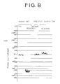
- the cassette recorder provided with the magnetic head device of the present invention produces output signals without phase differences in the normal direction reproduction and in the reverse direction reproduction.
- Fig. 8 shows characteristics of the magnetic head device of the present invention and the conventional magnetic head device shown in Figs. 9 and 10 when a magnetic tape of 10 kHz is reproduced. There is a large phase difference between the normal direction reproduction and the reverse direction reproduction with the conventional magnetic head device.
- the tape guides 22 and 27 are provided at both sides of the magnetic head 21.
- guides 22 and 27 are provided only on one side of the magnetic head, preferably on the downstream side of the magnetic head.
- the present invention provides a magnetic head device in which tape guides are integral with a supporting member for the magnetic head, whereby angle adjustment is not necessary and hence the device can easily be assembled at a low cost.
Landscapes
- Adjustment Of The Magnetic Head Position Track Following On Tapes (AREA)
Applications Claiming Priority (6)
| Application Number | Priority Date | Filing Date | Title |
|---|---|---|---|
| JP3546490 | 1990-02-16 | ||
| JP35464/90 | 1990-02-16 | ||
| JP26800790 | 1990-10-05 | ||
| JP268007/90 | 1990-10-05 | ||
| JP2314805A JPH04216354A (ja) | 1990-02-16 | 1990-11-20 | 磁気ヘッド装置 |
| JP314805/90 | 1990-11-20 |
Publications (3)
| Publication Number | Publication Date |
|---|---|
| EP0442512A2 true EP0442512A2 (de) | 1991-08-21 |
| EP0442512A3 EP0442512A3 (en) | 1992-04-15 |
| EP0442512B1 EP0442512B1 (de) | 1996-07-10 |
Family
ID=27288766
Family Applications (1)
| Application Number | Title | Priority Date | Filing Date |
|---|---|---|---|
| EP91102125A Revoked EP0442512B1 (de) | 1990-02-16 | 1991-02-14 | Magnetkopfvorrichtung für magnetische Bänder |
Country Status (4)
| Country | Link |
|---|---|
| US (1) | US5202808A (de) |
| EP (1) | EP0442512B1 (de) |
| JP (1) | JPH04216354A (de) |
| DE (1) | DE69120693T2 (de) |
Cited By (4)
| Publication number | Priority date | Publication date | Assignee | Title |
|---|---|---|---|---|
| EP0532012A3 (en) * | 1991-09-11 | 1994-08-10 | Matsushita Electric Industrial Co Ltd | Magnetic head assembly |
| EP0652557A3 (de) * | 1993-11-05 | 1995-07-26 | Philips Patentverwaltung | Magnetbandkassettengerät mit einer Bandführung für ein Magnetband im Bereich der Magnetspalten eines Magnetkopfes des Gerätes. |
| US5798898A (en) * | 1995-05-26 | 1998-08-25 | U.S. Philips Corporation | Magnetic head with a tape-guide device |
| CN1058351C (zh) * | 1992-02-25 | 2000-11-08 | 阿鲁普斯电气株式会社 | 磁带走带系统 |
Families Citing this family (6)
| Publication number | Priority date | Publication date | Assignee | Title |
|---|---|---|---|---|
| US5383076A (en) * | 1991-09-06 | 1995-01-17 | Pioneer Electronic Corp. | Magnetic head device with cleaning means for cleaning sliding surface thereof |
| US5357390A (en) * | 1991-12-11 | 1994-10-18 | U.S. Philips Corporation | Magnetic tape with a cylindrical magnetic head housing |
| JP2831513B2 (ja) * | 1992-07-09 | 1998-12-02 | アルプス電気株式会社 | 磁気ヘッド装置 |
| JPH08203166A (ja) * | 1994-11-15 | 1996-08-09 | Alps Electric Co Ltd | 磁気ヘッド装置 |
| JPH09282744A (ja) * | 1996-02-16 | 1997-10-31 | Canon Electron Inc | 磁気ヘッド装置及びその製造方法 |
| US5883770A (en) * | 1997-07-18 | 1999-03-16 | International Business Machines Corporation | Partial width mass produced linear tape recording head |
Family Cites Families (7)
| Publication number | Priority date | Publication date | Assignee | Title |
|---|---|---|---|---|
| NL8200175A (nl) * | 1981-04-13 | 1982-11-01 | Philips Nv | Magneetbandcassetteapparaat alsmede megneetkopeenheid toepasbaar bij een dergelijk apparaat. |
| NL8300730A (nl) * | 1983-02-28 | 1984-09-17 | Philips Nv | Magneetbandcassetteapparaat alsmede magneetkopeenheid toepasbaar bij een dergelijk apparaat. |
| JPS6077006A (ja) * | 1983-09-30 | 1985-05-01 | Electroplating Eng Of Japan Co | ロ−ラ装置 |
| JPH0411241Y2 (de) * | 1987-05-02 | 1992-03-19 | ||
| JPH05978Y2 (de) * | 1987-05-30 | 1993-01-12 | ||
| DE3812362A1 (de) * | 1988-04-14 | 1989-10-26 | Philips Patentverwaltung | Magnetbandkassettengeraet mit einer kopfplatte sowie eine magnetkopfeinheit fuer dieses magnetbandkassettengeraet |
| JP2678019B2 (ja) * | 1988-07-08 | 1997-11-17 | シャープ株式会社 | 磁気記録再生装置 |
-
1990
- 1990-11-20 JP JP2314805A patent/JPH04216354A/ja active Pending
-
1991
- 1991-02-14 EP EP91102125A patent/EP0442512B1/de not_active Revoked
- 1991-02-14 DE DE69120693T patent/DE69120693T2/de not_active Revoked
- 1991-02-15 US US07/655,692 patent/US5202808A/en not_active Expired - Lifetime
Cited By (6)
| Publication number | Priority date | Publication date | Assignee | Title |
|---|---|---|---|---|
| EP0532012A3 (en) * | 1991-09-11 | 1994-08-10 | Matsushita Electric Industrial Co Ltd | Magnetic head assembly |
| EP0769779A3 (de) * | 1991-09-11 | 1998-04-22 | Matsushita Electric Industrial Co., Ltd. | Magnetkopfzusammenbau |
| CN1058351C (zh) * | 1992-02-25 | 2000-11-08 | 阿鲁普斯电气株式会社 | 磁带走带系统 |
| EP0652557A3 (de) * | 1993-11-05 | 1995-07-26 | Philips Patentverwaltung | Magnetbandkassettengerät mit einer Bandführung für ein Magnetband im Bereich der Magnetspalten eines Magnetkopfes des Gerätes. |
| US5610787A (en) * | 1993-11-05 | 1997-03-11 | U.S. Philips Corporation | Magnetic tape apparatus with tape edge guides for reduced tape edge wear |
| US5798898A (en) * | 1995-05-26 | 1998-08-25 | U.S. Philips Corporation | Magnetic head with a tape-guide device |
Also Published As
| Publication number | Publication date |
|---|---|
| EP0442512B1 (de) | 1996-07-10 |
| JPH04216354A (ja) | 1992-08-06 |
| EP0442512A3 (en) | 1992-04-15 |
| DE69120693D1 (de) | 1996-08-14 |
| US5202808A (en) | 1993-04-13 |
| DE69120693T2 (de) | 1997-03-06 |
Similar Documents
| Publication | Publication Date | Title |
|---|---|---|
| KR920003989B1 (ko) | 자기테프 카세트장치 | |
| US5202808A (en) | Magnetic head device with tape guides for magnetic tapes | |
| US5467236A (en) | Gapped flexure tongue for floating type magnetic head apparatus | |
| EP0063398B1 (de) | Magnetbandkassettengerät und Magnetkopfeinheit zum Gebrauch mit einem solchen Gerät | |
| KR100256629B1 (ko) | 자기기록 재생장치 | |
| EP0449330B1 (de) | Bandkassettenladesystem | |
| US5831789A (en) | Disc recording and/or reproducing apparatus having a disc cassette loading/discharging mechanism with a lock member responsive to a cassette insertion to unlock a sliding member | |
| US4743992A (en) | Magnetic tape cassette | |
| US4875126A (en) | Stationary tape guide for a magnetic tape recorder | |
| US4110805A (en) | Magnetic tape cassette with oppositely inclined guide members flanking the recording/reproducing station | |
| US4205809A (en) | Tape cassette | |
| EP0661704A2 (de) | Kassette für Hochgeschwindigkeits-Bandtransport | |
| JP3785559B2 (ja) | 磁気テープカートリッジ | |
| US4939606A (en) | Rotary head assembly for digital audio tape recorders | |
| JP3443339B2 (ja) | テープレコーダのテープガイド機構 | |
| JPS59144061A (ja) | テ−プレコ−ダ | |
| JPH0413777Y2 (de) | ||
| JPH0544909Y2 (de) | ||
| JP2506664Y2 (ja) | テ―プガイド | |
| KR920006996Y1 (ko) | 카세트식 테이프 레코더용 헤드 주변기구 | |
| US6301083B1 (en) | Video tape recorder | |
| JP3166398B2 (ja) | データカートリッジ | |
| JPS587509Y2 (ja) | カセツトテ−プレコ−ダ | |
| JP3037104B2 (ja) | 先導ガイドブロック位置決め機構 | |
| JPH0320894Y2 (de) |
Legal Events
| Date | Code | Title | Description |
|---|---|---|---|
| PUAI | Public reference made under article 153(3) epc to a published international application that has entered the european phase |
Free format text: ORIGINAL CODE: 0009012 |
|
| 17P | Request for examination filed |
Effective date: 19910214 |
|
| AK | Designated contracting states |
Kind code of ref document: A2 Designated state(s): DE FR GB |
|
| PUAL | Search report despatched |
Free format text: ORIGINAL CODE: 0009013 |
|
| AK | Designated contracting states |
Kind code of ref document: A3 Designated state(s): DE FR GB |
|
| 17Q | First examination report despatched |
Effective date: 19940622 |
|
| GRAH | Despatch of communication of intention to grant a patent |
Free format text: ORIGINAL CODE: EPIDOS IGRA |
|
| GRAH | Despatch of communication of intention to grant a patent |
Free format text: ORIGINAL CODE: EPIDOS IGRA |
|
| GRAA | (expected) grant |
Free format text: ORIGINAL CODE: 0009210 |
|
| AK | Designated contracting states |
Kind code of ref document: B1 Designated state(s): DE FR GB |
|
| ET | Fr: translation filed | ||
| REF | Corresponds to: |
Ref document number: 69120693 Country of ref document: DE Date of ref document: 19960814 |
|
| REG | Reference to a national code |
Ref country code: GB Ref legal event code: 746 Effective date: 19970131 |
|
| PLBI | Opposition filed |
Free format text: ORIGINAL CODE: 0009260 |
|
| PLBQ | Unpublished change to opponent data |
Free format text: ORIGINAL CODE: EPIDOS OPPO |
|
| PLBF | Reply of patent proprietor to notice(s) of opposition |
Free format text: ORIGINAL CODE: EPIDOS OBSO |
|
| REG | Reference to a national code |
Ref country code: FR Ref legal event code: D6 |
|
| 26 | Opposition filed |
Opponent name: KANKE KIYOSHI Effective date: 19970410 |
|
| PLBF | Reply of patent proprietor to notice(s) of opposition |
Free format text: ORIGINAL CODE: EPIDOS OBSO |
|
| PLBF | Reply of patent proprietor to notice(s) of opposition |
Free format text: ORIGINAL CODE: EPIDOS OBSO |
|
| PLBQ | Unpublished change to opponent data |
Free format text: ORIGINAL CODE: EPIDOS OPPO |
|
| PLAB | Opposition data, opponent's data or that of the opponent's representative modified |
Free format text: ORIGINAL CODE: 0009299OPPO |
|
| R26 | Opposition filed (corrected) |
Opponent name: KANKE KIYOSHI Effective date: 19970410 |
|
| REG | Reference to a national code |
Ref country code: GB Ref legal event code: IF02 |
|
| PGFP | Annual fee paid to national office [announced via postgrant information from national office to epo] |
Ref country code: FR Payment date: 20030210 Year of fee payment: 13 |
|
| PGFP | Annual fee paid to national office [announced via postgrant information from national office to epo] |
Ref country code: GB Payment date: 20030212 Year of fee payment: 13 |
|
| PGFP | Annual fee paid to national office [announced via postgrant information from national office to epo] |
Ref country code: DE Payment date: 20030227 Year of fee payment: 13 |
|
| RDAH | Patent revoked |
Free format text: ORIGINAL CODE: EPIDOS REVO |
|
| RDAG | Patent revoked |
Free format text: ORIGINAL CODE: 0009271 |
|
| STAA | Information on the status of an ep patent application or granted ep patent |
Free format text: STATUS: PATENT REVOKED |
|
| 27W | Patent revoked |
Effective date: 20030406 |
|
| GBPR | Gb: patent revoked under art. 102 of the ep convention designating the uk as contracting state |
Free format text: 20030406 |