EP0442479B1 - Conteneur transportable pour stockage et/ou rangement, notamment pour outils - Google Patents
Conteneur transportable pour stockage et/ou rangement, notamment pour outils Download PDFInfo
- Publication number
- EP0442479B1 EP0442479B1 EP91102036A EP91102036A EP0442479B1 EP 0442479 B1 EP0442479 B1 EP 0442479B1 EP 91102036 A EP91102036 A EP 91102036A EP 91102036 A EP91102036 A EP 91102036A EP 0442479 B1 EP0442479 B1 EP 0442479B1
- Authority
- EP
- European Patent Office
- Prior art keywords
- linkage
- top wall
- handle
- panel
- lateral end
- Prior art date
- Legal status (The legal status is an assumption and is not a legal conclusion. Google has not performed a legal analysis and makes no representation as to the accuracy of the status listed.)
- Expired - Lifetime
Links
Images


Classifications
-
- B—PERFORMING OPERATIONS; TRANSPORTING
- B25—HAND TOOLS; PORTABLE POWER-DRIVEN TOOLS; MANIPULATORS
- B25H—WORKSHOP EQUIPMENT, e.g. FOR MARKING-OUT WORK; STORAGE MEANS FOR WORKSHOPS
- B25H3/00—Storage means or arrangements for workshops facilitating access to, or handling of, work tools or instruments
- B25H3/02—Boxes
- B25H3/021—Boxes comprising a number of connected storage elements
- B25H3/023—Boxes comprising a number of connected storage elements movable relative to one another for access to their interiors
Definitions
- the invention relates to a transportable, approximately cuboid storage and / or storage container for small parts, in particular tools, with a bottom, a rear wall, if necessary provided with suspension means, two side walls, a top wall, a front wall folding part, which has a front area the top wall-forming top wall folding part and side end parts, which complement the side walls, are connected and pivoted from a closed position about a pivot axis parallel to the rear wall through 180 ° to the open position, and vice versa, and a located above the top wall part, in Carrying handle extending in the longitudinal direction of the container, which can be detected regardless of whether the top wall-folding part-front wall-folding part unit is in the open or in the closed position.
- the handle is fixed in the region of the front edge of the base wall part, in the region of the center thereof, and a recess is arranged in the cover wall folding part, which allows the handle to pass through the cover wall part when folding the closed position to the open position, and vice versa.
- This design is disadvantageous in that the handle can only extend over a relatively small part of the length of the container due to the requirement of the cutout. As a result, it can only be grasped by one person and it is practically impossible to have a heavier box carried by two people.
- a handlebar arrangement which allows pivoting by 180 ° is arranged between the side end parts of the top wall-folding part-front wall-folding part unit and the associated side wall and which has a fixing point for each of the two ends of the over the entire length of the container extending carrying handle and with the help of the top panel folding part front panel part unit around the handle from the closed to the open position, and vice versa, is pivotable.
- the handle can be formed continuously over the entire length of the container, so that it is possible to carry a larger container in pairs.
- the introduction of the weight forces from the actual container onto the handle via the handlebars fixed on the side walls is advantageous, and there is no excessive stress on the base wall base.
- one and the same handlebar arrangement can be used for different sizes or lengths of containers or boxes, which particularly favors rational production.
- the elimination of the cutout in the conventional container in order to allow the handle to pass through during the pivoting process is now unnecessary.
- each handlebar arrangement for the forced control of the position of the handle relative to the side wall or to the side end part during pivoting comprises a handlebar articulated at one end to the side end part, which is articulated to the side wall , and on the other hand also a control link articulated to the side wall, which is pivotally connected to the side end part via a second coupling link.
- the handlebars expediently have a section projecting beyond the articulation point on which the control link acts, at the free end of which the fixing point for the handle is provided.
- the first coupling link in the area of the projecting section of the handlebar is articulated, in particular if the articulation point of the first coupling link is provided in relation to the handlebar at the fixing point for the handle.
- the first coupling link is connected to the side wall via a coupling link carrier fixed to the side wall and projecting beyond its upper edge.
- the feature has proven to be particularly favorable, according to which the handlebar is articulated on the side end part directly and indirectly via coupling arms and control arms dimensioned and fixed on the side wall in such a way that, in the closed position, it has a roughly together with the first coupling arm assumes a stretched position in which the distance al of the fixing point for the handle from the rear wall level is greater than the corresponding distance a2 after transfer to the open position in which the handlebar and the first coupling link assume a folded position.
- the handle In the open box position, in which the center of gravity of the box is closer to the rear wall than in the closed position, the handle is also in an approximate position in relation to the rear wall.
- the two handlebar assemblies each associated with the side walls each comprise only two handlebars, the first of which is articulated on the one hand on the handle support near the handle fixation point and on the other hand closely above the top panel folding part on the side end part and Of which the second in the open position of the container crossing the first handlebar (18) on the one hand in the area of contact between the top wall and the top wall folding part near the front edge of the top wall and on the other hand at the side end part near the front edge of the side end part but at a comparatively greater distance from the level of contact Cover wall and cover wall folding part is articulated.
- only the two handlebars of each handlebar arrangement are required in order to carry out a handlebar-controlled pivoting through 180 ° from the closed position into the open position and vice versa.
- the outermost handlebar of the handlebar arrangement is designed in the form of a disk which has at least part of the articulation points covers.
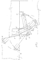
- the illustrated storage or storage container for small parts, in particular tools comprises a base 1, a rear wall 2, which is provided with suspension means in a manner not illustrated in order to be able to fix the container to a wall in the open state , two side walls 3, a top wall 4, a front wall folding part 5, which is connected to a top wall folding part 6 forming the front region of the top wall 4 and lateral end parts 7 which complement the side walls 3.
- This front wall folding part 5 is from a closed position, as illustrated in FIG. 1, about a pivot axis parallel to the rear wall 2 by 180 ° into that in FIG. 2 illustrated opening position, and vice versa, pivoted.
- a carrying handle 8 which extends in the longitudinal direction of the container and can be detected regardless of whether the top wall folding part front wall part unit is in the open or closed position.
- a link arrangement 9 which enables pivoting through 180 °.
- This handlebar assembly 9 comprises a fixing point 10 for each of the two ends of the handle 8 extending over the entire length of the container.
- each link arrangement for the forced control of the position of the handle 8 relative to the side wall 3 or to the side end part 7 during pivoting comprises a handlebar 11 articulated at one end to the side end part 11.
- a first coupling link 12 engages with it the side wall 3 is articulated.
- a control link 13 which is also connected to the side wall 7 in an articulated manner, is pivotally connected to the side end part 7 via a second coupling link 14.
- the handlebar 11 is provided with a section 16 projecting beyond the articulation point 15, on which the control link 13 engages, at the free end of which the fixing point 10 is provided for the handle.
- the first coupling link 12 is articulated in the region of the projecting section 16 of the handlebar 11, more precisely, the articulation point of the first coupling link 12 with respect to the handlebar 11 is provided at the fixing point 10 for the handle.
- first coupling link 12 is connected via a coupling link carrier 17 to the side wall 3, which projects beyond the upper edge of the side wall 3.
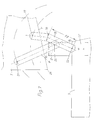
- FIG. 3 to 5 also show at which locations and with what relative dimensions the coupling links 12, 14 and the control link 13 are designed and arranged in relation to the handlebars 11.
- Fig. 5 shows that the handlebars 11 is articulated on the side end part 7 directly and indirectly via coupling arms 12, 14 and control arms 13 so dimensioned and fixed on the side wall 3 that in the closed position together with the first coupling arm 12 it is approximately elongated Takes position. In this position, the distance a1 of the fixing point 10 for the handle 8 from the rear wall level is greater than the corresponding distance a2 after being brought into the open position, cf. Fig. 3, in which the handlebar 11 and the first coupling link 12 assume a folded position.
- control link 13 is shown in the form of an obtuse-angled triangle, in the corner points of which the articulation points for fixing on the side wall 3 or for attacking the two coupling link 14 or the handlebar 11 are located.
- the relative position of these articulation points in relation to one another is also realized in the practical embodiment according to FIGS. 1 and 2.
- the control arm 13 is in the form of a disc. This is dimensioned so large that it covers part of the articulation points and a substantial part of the coupling and handlebars.
- each handlebar arrangement 9 comprises only two handlebars, namely a first handlebar 18 and a second handlebar 19.
- the first handlebar 18 is on the one hand on the handle support 17 'near the handle fixing point 10 and on the other hand close above the top panel folding part 6 on the side End part 7 articulated.
- the second link 19 is crossing the first link on the one hand in the area of the contact plane B of the top wall 4 and the top wall folding part 6 near the front edge 4 'of the top wall 4 and on the side end part 7 near the front edge 7' of the lateral end part 7, however, articulated at a comparatively greater distance from the contact plane B of the top wall 4 and top wall folding part 6.
- the distances b1 and b2 of the articulation points 20, 21 and 22, 23 of each of the two links 18 and 19 are, as can easily be seen in the drawing, approximately the same size.
- the drawing also clarifies that the distance b3 of the articulation point 21 of the first link 18 on the lateral end part 7 from the articulation point 23 of the second link 19 on the lateral end part 7 is approximately 3/4 of the distance b1 of the articulation points 20 and 21 of the first link 18 or the articulation points 22 and 23 of the second link 19 from each other.
- the articulation point 22 of the second link 19 located in the area of the contact plane B of the top wall 4 and top wall folding part 6 is provided in the middle between the upper front edge 24 of the side wall 3 and the lower front edge 25 of the side end part 7.
- the distance b4 of the articulation point 21 of the first link 18 from the contact plane B of the top wall 4 and the top wall folding part 6, on the one hand, and the distance b5 of the articulation point 23 of the second link 19 from the front edge 7 'of the side end part 7, on the other hand, are of approximately the same size. These distances b4 and b5 are just under 1/5 of the distance b1 and b2 of the articulation points 20 and 21 of the first link 18 and the articulation points 22 and 23 of the second link 19 from one another.
- the second link 19 has an angled portion in the area with which it passes the outer end of the handle support 17 'when pivoted.
- this area which is indicated in more detail by a wavy line 26, the handlebar end leading to the articulation point 23 is bent in order to take into account the thickness of the material of the handle support 17 'and the first link 18 compared to the handlebar end leading to the articulation point 22.
- the second link 19 can be at least partially disk-shaped, expediently with a radius of a length which corresponds to the distance b6 between the articulation point 22 and the region 26 having the offset.
- the inside of the container is provided with conventional storage boards or devices for the safe, orderly storage of small parts, in the case of a tool box with means for holding the various tools and accessories.
- the interior of the container has not been shown.
Landscapes
- Engineering & Computer Science (AREA)
- Mechanical Engineering (AREA)
- Details Of Rigid Or Semi-Rigid Containers (AREA)
- Thermotherapy And Cooling Therapy Devices (AREA)
- Workshop Equipment, Work Benches, Supports, Or Storage Means (AREA)
Claims (13)
- Conteneur transportable pour le stockage et/ou le rangement, de forme à peu près parallélipipédique, pour des petites pièces, notamment des outils, comprenant un fond (1), une paroi arrière (2) pourvue le cas échéant de moyens d'accrochage, deux parois latérales (3), une paroi de recouvrement (4), un rabat de paroi avant (5) qui est relié à un rabat de paroi de recouvrement (6) constituant la zone avant de la paroi de recouvrement et à des parties terminales latérales (7) qui complètent les parois latérales (3) et qui est monté de façon pivotante à partir d'une position de fermeture autour d'un axe de pivotement parallèle à la paroi arrière de 180° dans la position d'ouverture et inversement, et une poignée (8) disposée au-dessus de la partie de base de la paroi de recouvrement et s'étendant dans la direction longitudinale du conteneur, qui peut être saisie indépendamment du fait que l'unité constituée par le rabat de paroi de recouvrement et le rabat de paroi avant (5,6) se trouve dans la position d'ouverture ou de fermeture, caractérisé en ce qu'un agencement à bielles (9) est disposé entre les parties terminales latérales (7) de l'unité (5, 6) constituée du rabat de paroi de recouvrement et du rabat de paroi avant et de la paroi latérale associée (3), permettant à chaque fois le pivotement de 180°, qui comprend un point de fixation (10) pour l'une des deux extrémités, respectivement, de la poignée (8) s'étendant sur toute la longueur du conteneur, et à l'aide duquel l'unité (5, 6) constituée du rabat de paroi de recouvrement et du rabat de paroi avant peut être pivotée autour de la poignée (8) de la position de fermeture dans la position d'ouverture et inversement.
- Conteneur selon la revendication 1, caractérisé en ce que chaque agencement à billes (9) pour la commande forcée de la position de la poignée (8) relativement à la paroi latérale (3) et à la partie terminale latérale (7), respectivement, entoure pendant le pivotement une bielle formant poignée (11) articulée par l'une de ses extrémités à la partie terminale latérale, contre laquelle s'applique, d'une part, une première bielle d'accouplement (12) qui est reliée de façon articulée à la paroi latérale (3) et d'autre part une bielle de commande (13) reliée également de façon articulée à la paroi latérale qui est connectée de façon pivotante par une deuxième bielle d'accouplement (14) à la partie terminale latérale (7).
- Conteneur selon la revendication 1 ou 2, caractérisé en ce que la bielle formant poignée (11) présente une section (16) en saillie sur le point d'articulation (15) contre lequel s'applique la bielle de commande (13), et à l'extrémité libre de laquelle est prévu le point de fixation (10) pour la poignée (8).
- Conteneur selon l'une des revendications 1 à 3, caractérisé en ce que la première bielle d'accouplement (12) est articulée au voisinage du tronçon en saillie (16) de la bielle formant poignée (11).
- Conteneur selon l'une des revendications 1 à 4, caractérisé en ce que l'emplacement d'articulation de la première bielle d'accouplement (12) est prévu relativement à la bielle formant poignée (11) au point de fixation (10) de la poignée (8).
- Conteneur selon l'une des revendications 1 à 5, caractérisé en ce que la première bielle d'accouplement (12) est reliée à la paroi latérale (13) par un support de bielle d'accouplement (17) fixé à la paroi latérale (3) et faisant saillie sur le bord supérieur de celle-ci.
- Conteneur selon l'une des revendications 1 à 6, caractérisé en ce que la bielle formant poignée (11) est articulée de telle façon à la partie terminale latérale (7) directement ainsi qu'indirectement, par des bielles d'accouplement (12,14) ainsi dimensionnées et fixées et une bielle de commande (13) à la paroi latérale (3) qu'elle occupe dans la position de fermeture conjointement avec la première bielle d'accouplement (12) une position à peu près allongée dans laquelle l'écart (a1) du point de fixation (10) pour la poignée (8) du plan de paroi arrière est plus grand que l'écart correspondant (a2) après le passage dans la position d'ouverture dans laquelle la bielle à poignée (11) et la première bielle d'accouplement (12) occupent une position rabattue.
- Conteneur selon l'une des revendications 1 à 7, caractérisé en ce que la bielle de commande (13) est réalisée sous forme d'un disque qui est dimensionné suivant une taille suffisante pour recouvrir une partie des emplacements d'articulation.
- Conteneur selon la revendication 1, caractérisé en ce qu'un support de poignée (17') est fixé aux deux parois latérales (3), en faisant saillie à chaque fois sur le bord supérieur de celles-ci, présentant le point de fixation (10) de la poignée (8), et en ce que les deux agencements à bielles (9) associés respectivement aux parois latérales (3) comprennent, respectivement, seulement deux bielles (18,19) dont la première, respectivement, (18) est articulée, d'une part, au support de poignée (17') au voisinage du point de fixation (10) de la poignée et, d'autre part tout près au-dessus du rabat de paroi de recouvrement (6) à la partie terminale latérale (7), et dont la deuxième, respectivement, (19) tout en croisant dans la position d'ouverture du conteneur la première bielle (18), est articulée d'une part au voisinage du plan de contact (B) de la paroi de recouvrement (4) et du rabat de paroi de recouvrement (6) près de l'arête avant de la paroi de recouvrement (4) et, d'autre part, à la partie terminale latérale (7) près de l'arête avant (7') de la partie terminale latérale (7), cependant à une distance comparativement plus grande du plan de contact (B) de la paroi de recouvrement (4) et du rabat de paroi de recouvrement (6).
- Conteneur selon la revendication 9, caractérisé en ce que les écarts (b1,b2) des points d'articulation (20, 21; 22, 23) de chacune des deux bielles (18, 19) sont à peu près de même grandeur.
- Conteneur selon la revendication 10, caractérisé en ce que l'écart (b3) du point d'articulation (21) de la première bielle (18) à la partie terminale latérale (7) du point d'articulation (23) de la deuxième bielle (19) à la partie terminale latérale (7) représente à peu près 3/4 de l'écart des points d'articulation (20,21) de la première bielle (18) et des points d'articulation (22, 23), respectivement, de la deuxième bielle (19).
- Conteneur selon l'une des revendications 9 ou 10, caractérisé en ce que le point d'articulation (22) de la deuxième bielle (19) se trouvant au voisinage du plan de contact (B) de la paroi de recouvrement (4) et du rabat de paroi de recouvrement (6) se situe au milieu entre l'arête avant supérieure (24) de la paroi latérale (3) et l'arête avant inférieure (25) de la partie terminale latérle (7).
- Conteneur selon l'une des revendications 10 à 12, caractérisé en ce que les écarts (b4) du point d'articulation (21) de la première bielle (18) par rapport au plan de contact (B) de la paroi de recouvrement (4) et du rabat de paroi de recouvrement (6) d'une part, et le point d'articulation (23) de la deuxième bielle (19) par rapport à l'arête avant (7') de la partie terminale latérale (7) d'autre part, sont à peu près de même grandeur et représentent de préférence à peine 1/5 des écarts (b1,b2) des points d'articulation (20,21) de la première bielle (18) et des points d'articulation (22, 23), respectivement, de la deuxième bielle (19).
Applications Claiming Priority (4)
| Application Number | Priority Date | Filing Date | Title |
|---|---|---|---|
| DE4004574 | 1990-02-14 | ||
| DE4004574 | 1990-02-14 | ||
| DE4024304A DE4024304A1 (de) | 1990-02-14 | 1990-07-31 | Transportabler vorrats- und/oder lagerbehaelter, insbesondere fuer werkzeuge |
| DE4024304 | 1990-07-31 |
Publications (2)
| Publication Number | Publication Date |
|---|---|
| EP0442479A1 EP0442479A1 (fr) | 1991-08-21 |
| EP0442479B1 true EP0442479B1 (fr) | 1993-07-28 |
Family
ID=25890119
Family Applications (1)
| Application Number | Title | Priority Date | Filing Date |
|---|---|---|---|
| EP91102036A Expired - Lifetime EP0442479B1 (fr) | 1990-02-14 | 1991-02-13 | Conteneur transportable pour stockage et/ou rangement, notamment pour outils |
Country Status (5)
| Country | Link |
|---|---|
| EP (1) | EP0442479B1 (fr) |
| AT (1) | ATE91942T1 (fr) |
| DE (2) | DE4024304A1 (fr) |
| DK (1) | DK0442479T3 (fr) |
| ES (1) | ES2044627T3 (fr) |
Cited By (1)
| Publication number | Priority date | Publication date | Assignee | Title |
|---|---|---|---|---|
| DE102010052398A1 (de) | 2010-06-28 | 2011-12-29 | Ulrich Witt | Griffeinheit mit einem Behältnis, welches variable Transport- und Öffnungsfunktion beinhaltet und sich zum Transportieren von Handwerkz. od. dgl eignet |
Families Citing this family (2)
| Publication number | Priority date | Publication date | Assignee | Title |
|---|---|---|---|---|
| DE102004053524A1 (de) * | 2004-11-05 | 2006-05-11 | Wero-Medical, Werner Michallik Gmbh & Co Kg | Verbandstoffbehälter |
| US8534779B2 (en) | 2010-10-06 | 2013-09-17 | Kenneth Schaaf | Portable station |
Family Cites Families (7)
| Publication number | Priority date | Publication date | Assignee | Title |
|---|---|---|---|---|
| US1345247A (en) * | 1920-01-13 | 1920-06-29 | Orlando B Robbins | Combination tool-box and sawhorse |
| CH223471A (de) * | 1940-10-04 | 1942-09-15 | Kron Karl | Einseitig wirkendes Scharnierband. |
| FR1076887A (fr) * | 1953-05-13 | 1954-11-02 | Chambonne | Dispositif permettant l'effacement de la barre-poignée des coffrets d'outillage à plusieurs casiers, après déploiement des casiers |
| DE3210721A1 (de) * | 1982-03-24 | 1983-10-06 | Kueffner Reinhold Innenausbau | Anlenkbeschlag fuer gebaeude- und moebel-tueren, bzw. -fenster |
| FR2573636B1 (fr) * | 1984-11-29 | 1987-02-13 | Payen Raoul | Valise rayonnage |
| DE3507953A1 (de) * | 1985-03-06 | 1986-09-18 | Alfred 8910 Landsberg Weber | Werkzeugkasten |
| US4613041A (en) * | 1985-06-18 | 1986-09-23 | Carlton Robert E | Portable storage kit for household cleansers |
-
1990
- 1990-07-31 DE DE4024304A patent/DE4024304A1/de not_active Withdrawn
-
1991
- 1991-02-13 DE DE9191102036T patent/DE59100211D1/de not_active Expired - Fee Related
- 1991-02-13 AT AT91102036T patent/ATE91942T1/de not_active IP Right Cessation
- 1991-02-13 ES ES91102036T patent/ES2044627T3/es not_active Expired - Lifetime
- 1991-02-13 DK DK91102036.0T patent/DK0442479T3/da active
- 1991-02-13 EP EP91102036A patent/EP0442479B1/fr not_active Expired - Lifetime
Cited By (1)
| Publication number | Priority date | Publication date | Assignee | Title |
|---|---|---|---|---|
| DE102010052398A1 (de) | 2010-06-28 | 2011-12-29 | Ulrich Witt | Griffeinheit mit einem Behältnis, welches variable Transport- und Öffnungsfunktion beinhaltet und sich zum Transportieren von Handwerkz. od. dgl eignet |
Also Published As
| Publication number | Publication date |
|---|---|
| ES2044627T3 (es) | 1994-01-01 |
| DE4024304A1 (de) | 1991-08-22 |
| EP0442479A1 (fr) | 1991-08-21 |
| ATE91942T1 (de) | 1993-08-15 |
| DK0442479T3 (da) | 1993-12-27 |
| DE59100211D1 (de) | 1993-09-02 |
Similar Documents
| Publication | Publication Date | Title |
|---|---|---|
| DE4327869C1 (de) | Ablagefach mit Schließklappe und an dieser angeordnetem Klapptisch | |
| EP1698247A2 (fr) | Boîte à outils à coque dure et charnière pour une valise | |
| EP1884438B1 (fr) | Chariot pour pièces de petite taille | |
| DE2729767C2 (de) | Anordnung zur Unterbringung von Skiern und Zubehör | |
| EP0141398B1 (fr) | Chariot à provisions encastrable | |
| EP0442479B1 (fr) | Conteneur transportable pour stockage et/ou rangement, notamment pour outils | |
| DE2614906A1 (de) | Schwenkbare tragvorrichtung fuer einen abfallsammler | |
| DE3902277C1 (fr) | ||
| EP0011297B1 (fr) | Récipient, en particulier récipient à ordures, avec un couvercle abattant-coulissant pour la partie avant et avec un second couvercle pour la partie arrière de l'ouverture du récipient | |
| DE2040185B2 (de) | Wandschrank, insbesondere für Schlüssel | |
| EP1354824B1 (fr) | Jeu d'éléments pour récipient à ordures avec des poignées enfichables | |
| EP0633101B1 (fr) | Cassette pour le rangement d'articles | |
| DE10202058C1 (de) | Schrankkorpus mit angelenkter und Verschließbarer Schranktüre | |
| DE3511955C2 (fr) | ||
| DE4033548A1 (de) | Einkaufswagen | |
| EP0308713B1 (fr) | Chariot à emplettes | |
| CH624638A5 (en) | Rubbish container | |
| EP0338341A2 (fr) | Armoire de commutation à cadre pivotant | |
| DE7811011U1 (de) | Klappenbeschlag | |
| DE1299382B (de) | Kochtopf mit abnehmbarem Deckel | |
| DE2914326C2 (de) | Vorrichtung zur Halterung eines Müllbehälters | |
| DE3304656A1 (de) | Hubkippvorrichtung fuer grossvolumige klappdeckel-muellbehaelter | |
| DE19821408A1 (de) | Schließe für eine Tür oder eine Ladewand | |
| DE19713297A1 (de) | Ständer zur Halterung von Säcken | |
| DE1753117C3 (de) | Verkaufsautomatentüre |
Legal Events
| Date | Code | Title | Description |
|---|---|---|---|
| PUAI | Public reference made under article 153(3) epc to a published international application that has entered the european phase |
Free format text: ORIGINAL CODE: 0009012 |
|
| AK | Designated contracting states |
Kind code of ref document: A1 Designated state(s): AT BE CH DE DK ES FR GB IT LI NL SE |
|
| 17P | Request for examination filed |
Effective date: 19910821 |
|
| 17Q | First examination report despatched |
Effective date: 19921207 |
|
| GRAA | (expected) grant |
Free format text: ORIGINAL CODE: 0009210 |
|
| AK | Designated contracting states |
Kind code of ref document: B1 Designated state(s): AT BE CH DE DK ES FR GB IT LI NL SE |
|
| REF | Corresponds to: |
Ref document number: 91942 Country of ref document: AT Date of ref document: 19930815 Kind code of ref document: T |
|
| REF | Corresponds to: |
Ref document number: 59100211 Country of ref document: DE Date of ref document: 19930902 |
|
| ITF | It: translation for a ep patent filed |
Owner name: ING. C. GREGORJ S.P.A. |
|
| GBT | Gb: translation of ep patent filed (gb section 77(6)(a)/1977) |
Effective date: 19931101 |
|
| ET | Fr: translation filed | ||
| REG | Reference to a national code |
Ref country code: DK Ref legal event code: T3 |
|
| REG | Reference to a national code |
Ref country code: ES Ref legal event code: FG2A Ref document number: 2044627 Country of ref document: ES Kind code of ref document: T3 |
|
| PLBE | No opposition filed within time limit |
Free format text: ORIGINAL CODE: 0009261 |
|
| STAA | Information on the status of an ep patent application or granted ep patent |
Free format text: STATUS: NO OPPOSITION FILED WITHIN TIME LIMIT |
|
| 26N | No opposition filed | ||
| EAL | Se: european patent in force in sweden |
Ref document number: 91102036.0 |
|
| PGFP | Annual fee paid to national office [announced via postgrant information from national office to epo] |
Ref country code: SE Payment date: 19980127 Year of fee payment: 8 |
|
| PGFP | Annual fee paid to national office [announced via postgrant information from national office to epo] |
Ref country code: DK Payment date: 19980220 Year of fee payment: 8 |
|
| PGFP | Annual fee paid to national office [announced via postgrant information from national office to epo] |
Ref country code: BE Payment date: 19980223 Year of fee payment: 8 |
|
| PGFP | Annual fee paid to national office [announced via postgrant information from national office to epo] |
Ref country code: ES Payment date: 19980416 Year of fee payment: 8 |
|
| PG25 | Lapsed in a contracting state [announced via postgrant information from national office to epo] |
Ref country code: SE Free format text: LAPSE BECAUSE OF NON-PAYMENT OF DUE FEES Effective date: 19990214 |
|
| PG25 | Lapsed in a contracting state [announced via postgrant information from national office to epo] |
Ref country code: ES Free format text: LAPSE BECAUSE OF NON-PAYMENT OF DUE FEES Effective date: 19990215 |
|
| PG25 | Lapsed in a contracting state [announced via postgrant information from national office to epo] |
Ref country code: BE Free format text: LAPSE BECAUSE OF NON-PAYMENT OF DUE FEES Effective date: 19990228 |
|
| PG25 | Lapsed in a contracting state [announced via postgrant information from national office to epo] |
Ref country code: DK Free format text: LAPSE BECAUSE OF NON-PAYMENT OF DUE FEES Effective date: 19990301 |
|
| BERE | Be: lapsed |
Owner name: ENTHOLZNER HANS-PETER Effective date: 19990228 |
|
| EUG | Se: european patent has lapsed |
Ref document number: 91102036.0 |
|
| PGFP | Annual fee paid to national office [announced via postgrant information from national office to epo] |
Ref country code: GB Payment date: 20000203 Year of fee payment: 10 |
|
| REG | Reference to a national code |
Ref country code: DK Ref legal event code: EBP |
|
| PGFP | Annual fee paid to national office [announced via postgrant information from national office to epo] |
Ref country code: NL Payment date: 20000229 Year of fee payment: 10 |
|
| PGFP | Annual fee paid to national office [announced via postgrant information from national office to epo] |
Ref country code: CH Payment date: 20000308 Year of fee payment: 10 |
|
| PGFP | Annual fee paid to national office [announced via postgrant information from national office to epo] |
Ref country code: AT Payment date: 20010126 Year of fee payment: 11 |
|
| PG25 | Lapsed in a contracting state [announced via postgrant information from national office to epo] |
Ref country code: GB Free format text: LAPSE BECAUSE OF NON-PAYMENT OF DUE FEES Effective date: 20010213 |
|
| PGFP | Annual fee paid to national office [announced via postgrant information from national office to epo] |
Ref country code: FR Payment date: 20010227 Year of fee payment: 11 |
|
| PG25 | Lapsed in a contracting state [announced via postgrant information from national office to epo] |
Ref country code: CH Free format text: LAPSE BECAUSE OF NON-PAYMENT OF DUE FEES Effective date: 20010228 Ref country code: LI Free format text: LAPSE BECAUSE OF NON-PAYMENT OF DUE FEES Effective date: 20010228 |
|
| REG | Reference to a national code |
Ref country code: ES Ref legal event code: FD2A Effective date: 20010503 |
|
| PG25 | Lapsed in a contracting state [announced via postgrant information from national office to epo] |
Ref country code: NL Free format text: LAPSE BECAUSE OF NON-PAYMENT OF DUE FEES Effective date: 20010901 |
|
| REG | Reference to a national code |
Ref country code: CH Ref legal event code: PL |
|
| GBPC | Gb: european patent ceased through non-payment of renewal fee |
Effective date: 20010213 |
|
| NLV4 | Nl: lapsed or anulled due to non-payment of the annual fee |
Effective date: 20010901 |
|
| PG25 | Lapsed in a contracting state [announced via postgrant information from national office to epo] |
Ref country code: AT Free format text: LAPSE BECAUSE OF NON-PAYMENT OF DUE FEES Effective date: 20020213 |
|
| PG25 | Lapsed in a contracting state [announced via postgrant information from national office to epo] |
Ref country code: FR Free format text: LAPSE BECAUSE OF NON-PAYMENT OF DUE FEES Effective date: 20021031 |
|
| REG | Reference to a national code |
Ref country code: FR Ref legal event code: ST |
|
| PG25 | Lapsed in a contracting state [announced via postgrant information from national office to epo] |
Ref country code: IT Free format text: LAPSE BECAUSE OF NON-PAYMENT OF DUE FEES Effective date: 20050213 |
|
| PGFP | Annual fee paid to national office [announced via postgrant information from national office to epo] |
Ref country code: DE Payment date: 20060118 Year of fee payment: 16 |
|
| PG25 | Lapsed in a contracting state [announced via postgrant information from national office to epo] |
Ref country code: DE Free format text: LAPSE BECAUSE OF NON-PAYMENT OF DUE FEES Effective date: 20070901 |