EP0442479B1 - Transportable storage bin and/or tool-box, in particular for tools - Google Patents
Transportable storage bin and/or tool-box, in particular for tools Download PDFInfo
- Publication number
- EP0442479B1 EP0442479B1 EP91102036A EP91102036A EP0442479B1 EP 0442479 B1 EP0442479 B1 EP 0442479B1 EP 91102036 A EP91102036 A EP 91102036A EP 91102036 A EP91102036 A EP 91102036A EP 0442479 B1 EP0442479 B1 EP 0442479B1
- Authority
- EP
- European Patent Office
- Prior art keywords
- linkage
- top wall
- handle
- panel
- lateral end
- Prior art date
- Legal status (The legal status is an assumption and is not a legal conclusion. Google has not performed a legal analysis and makes no representation as to the accuracy of the status listed.)
- Expired - Lifetime
Links
Images


Classifications
-
- B—PERFORMING OPERATIONS; TRANSPORTING
- B25—HAND TOOLS; PORTABLE POWER-DRIVEN TOOLS; MANIPULATORS
- B25H—WORKSHOP EQUIPMENT, e.g. FOR MARKING-OUT WORK; STORAGE MEANS FOR WORKSHOPS
- B25H3/00—Storage means or arrangements for workshops facilitating access to, or handling of, work tools or instruments
- B25H3/02—Boxes
- B25H3/021—Boxes comprising a number of connected storage elements
- B25H3/023—Boxes comprising a number of connected storage elements movable relative to one another for access to their interiors
Abstract
Description
Die Erfindung bezieht sich auf einen transportablen, etwa quaderförmig ausgebildeten Vorrats- und/oder Lagerbehälter für Kleinteile, insbesondere Werkzeuge, mit einem Boden, einer ggfs. mit Aufhängemitteln versehenen Rückwand, zwei Seitenwänden, einer Deckwand, einem Vorderwandklappteil, der mit einem den vorderen Bereich der Deckwand bildenden Deckwandklappteil und seitlichen Endteilen, die die Seitenwände ergänzen, verbunden und aus einer Schließstellung um eine zur Rückwand parallele Schwenkachse um 180° in die Öffnungsstellung, und umgekehrt, schwenkbar gelagert ist, und einem oberhalb des Deckwandgrundteils angeordneten, sich in Behälterlängsrichtung erstreckenden Tragegriff, der unabhängig davon, ob sich die Deckwandklappteil-Vorderwandklappteil-Einheit in Öffnungs- oder in Schließstellung befindet, erfaßbar ist.The invention relates to a transportable, approximately cuboid storage and / or storage container for small parts, in particular tools, with a bottom, a rear wall, if necessary provided with suspension means, two side walls, a top wall, a front wall folding part, which has a front area the top wall-forming top wall folding part and side end parts, which complement the side walls, are connected and pivoted from a closed position about a pivot axis parallel to the rear wall through 180 ° to the open position, and vice versa, and a located above the top wall part, in Carrying handle extending in the longitudinal direction of the container, which can be detected regardless of whether the top wall-folding part-front wall-folding part unit is in the open or in the closed position.
Bei einem bekannten Werkzeugkasten dieser Art (EP-A-0193879) ist der Tragegriff im Bereich der Vorderkante des Deckwandgrundteils, und zwar im Bereich von dessen Mitte festgelegt und im Deckwandklappteil ist eine Ausnehmung angeordnet, die dem Tragegriff den Durchtritt durch den Deckwandklappteil beim Klappen von der Schließstellung in die Öffnungsstellung, und umgekehrt, gewährt. Diese Ausführung ist insofern nachteilig, als sich der Griff - bedingt durch das Erfordernis des Ausschnitts - nur über einen relativ kleinen Teil der Länge des Behälters erstrecken kann. Infolgedessen läßt er sich nur von einer Person erfassen, und es ist praktisch unmöglich, einen schwereren Kasten von zwei Personen tragen zu lassen. Außerdem ist es fertigungstechnisch umständlich und aufwendig, jeweils die Ausnehmung im Deckwandklappteil vorzusehen, die den Durchtritt des Tragegriffs beim Verschwenken der Deckwandklappteil-Vorderwandklappteil-Einheit ermöglicht. Auch die Tatsache, daß das Gesamtgewicht des Kastens nebst Inhalt vom Boden und den Seitenwänden über das sich horizontal erstreckende, vorwiegend auf Biegung beanspruchte Deckwandgrundteil zum Tragegriff hin übertragen werden muß, hat sich als ungünstig herausgestellt, da letzteres auf die auftretenden möglichen höheren Belastungen ausgelegt sein muß.In a known tool box of this type (EP-A-0193879), the handle is fixed in the region of the front edge of the base wall part, in the region of the center thereof, and a recess is arranged in the cover wall folding part, which allows the handle to pass through the cover wall part when folding the closed position to the open position, and vice versa. This design is disadvantageous in that the handle can only extend over a relatively small part of the length of the container due to the requirement of the cutout. As a result, it can only be grasped by one person and it is practically impossible to have a heavier box carried by two people. In addition, it is technically cumbersome and complex to provide the recess in the top wall folding part, which enables the passage of the handle when pivoting the top wall folding part front wall part unit. The fact that the total weight of the box and its contents must be transferred from the floor and the side walls to the handle via the horizontally extending top wall base, which is mainly subject to bending, has also proven to be unfavorable, since the latter is designed for the possible higher loads that occur got to.
Überraschenderweise wurde festgestellt, daß sich die genannten Mängel erfindungsgemäß beseitigen lassen, wenn zwischen den seitlichen Endteilen der Deckwandklappteil-Vorderwandklappteil-Einheit und der zugehörigen Seitenwand jeweils eine das Verschwenken um 180° ermöglichende Lenkeranordnung angeordnet ist, die einen Fixierpunkt für jeweils eines der beiden Enden des sich über die ganze Behälterlänge erstreckenden Tragegriffs umfaßt und mit deren Hilfe die Deckwandklappteil-Vorderwandklappteil-Einheit um den Tragegriff herum aus der Schließ- in die Öffnungsstellung, und umgekehrt, verschwenkbar ist. Bei einer derartigen Behälterausgestaltung kann der Griff durchgehend über die gesamte Behälterlänge ausgebildet sein, so daß die Möglichkeit gegeben ist, einen größeren Behälter zu zweit zu tragen. Dabei ist in vorteilhafter Weise die Einleitung der Gewichtskräfte vom eigentlichen Behälter auf den Tragegriff über die an den Seitenwänden festgelegten Lenker gegeben, und es kommt nicht zu einer übermäßigen Beanspruchung des Deckwandgrundteils. Außerdem ist der Vorteil gegeben, daß ein und dieselbe Lenkeranordnung für unterschiedliche Größen bzw. Längen von Behältern bzw. Kästen einsetzbar ist, was eine rationelle Fertigung besonders begünstigt. Der Fortfall des Ausschnittes beim herkömmlichen Behälter, um den Durchtritt des Griffs während des Schwenkvorgangs zu ermöglichen, ist nunmehr entbehrlich.Surprisingly, it was found that the above-mentioned shortcomings can be eliminated according to the invention if a handlebar arrangement which allows pivoting by 180 ° is arranged between the side end parts of the top wall-folding part-front wall-folding part unit and the associated side wall and which has a fixing point for each of the two ends of the over the entire length of the container extending carrying handle and with the help of the top panel folding part front panel part unit around the handle from the closed to the open position, and vice versa, is pivotable. With such a container design, the handle can be formed continuously over the entire length of the container, so that it is possible to carry a larger container in pairs. In this case, the introduction of the weight forces from the actual container onto the handle via the handlebars fixed on the side walls is advantageous, and there is no excessive stress on the base wall base. In addition, there is the advantage that one and the same handlebar arrangement can be used for different sizes or lengths of containers or boxes, which particularly favors rational production. The elimination of the cutout in the conventional container in order to allow the handle to pass through during the pivoting process is now unnecessary.
Als in baulicher Hinsicht sehr günstig hat es sich herausgestellt, wenn jede Lenkeranordnung zur Zwangssteuerung der Position des Tragegriffs relativ zur Seitenwand bzw. zum seitlichen Endteil während des Verschwenkens einen mit seinem einen Ende am seitlichen Endteil angelenkten Grifflenker umfaßt, der mit der Seitenwand gelenkig verbunden ist, und andererseits einen ebenfalls mit der Seitenwand gelenkig verbundener Steuerlenker, der über einen zweiten Koppellenker an das seitliche Endteil schwenkbar angeschlossen ist.From a structural point of view, it has turned out to be advantageous if each handlebar arrangement for the forced control of the position of the handle relative to the side wall or to the side end part during pivoting comprises a handlebar articulated at one end to the side end part, which is articulated to the side wall , and on the other hand also a control link articulated to the side wall, which is pivotally connected to the side end part via a second coupling link.
Zweckmäßigerweise weist der Grifflenker einen über den Gelenkpunkt, an dem der Steuerlenker angreift, vorstehenden Abschnitt auf, an dessen freiem Ende der Fixierpunkt für den Tragegriff vorgesehen ist.The handlebars expediently have a section projecting beyond the articulation point on which the control link acts, at the free end of which the fixing point for the handle is provided.
Besonders günstig im Hinblick auf eine gedrungene Ausführung ist es, wenn der erste Koppellenker im Bereich des vorstehenden Abschnitts des Grifflenkers angelenkt ist, und zwar insbesondere, wenn die Anlenkstelle des ersten Koppellenkers in Bezug auf den Grifflenker am Fixierpunkt für den Tragegriff vorgesehen ist.With regard to a compact design, it is particularly favorable if the first coupling link in the area of the projecting section of the handlebar is articulated, in particular if the articulation point of the first coupling link is provided in relation to the handlebar at the fixing point for the handle.
Als in funktioneller und baulicher Hinsicht sehr vorteilhaft hat es sich erwiesen, wenn der erste Koppellenker über einen an der Seitenwand festgelegten und über ihren oberen Rand vorstehenden Koppellenkerträger mit der Seitenwand verbunden ist.It has proven to be very advantageous from a functional and structural point of view if the first coupling link is connected to the side wall via a coupling link carrier fixed to the side wall and projecting beyond its upper edge.
Bei der eingangs erwähnten herkömmlichen Ausführung (EP-A- 0193879) behält der Tragegriff unabhängig davon, ob sich der Werkzeugkasten in Schließ- oder in Öffnungsposition befindet, stets seine Lage in Bezug zur Kastenrückwand bei, so daß die sich beim Öffnen ergebende Schwerpunktverlagerung keine Berücksichtigung findet. Als besonders günstig hat sich deshalb in weiterer Ausgestaltung der Erfindung das Merkmal erwiesen, wonach der Grifflenker derart am seitlichen Endteil unmittelbar sowie mittelbar über so bemessene und festgelegte Koppellenker und Steuerlenker an der Seitenwand angelenkt ist, daß er in Schließstellung zusammen mit dem ersten Koppellenker eine etwa gestreckte Lage einnimmt, in der der Abstand al des Fixierpunktes für den Tragegriff von der Rückwandebene größer ist als der entsprechende Abstand a2 nach Überführung in die Öffnungsstellung, in der der Grifflenker und der erste Koppellenker eine zusammengeklappte Lage einnehmen. In geöffneter Kastenposition, bei der der Schwerpunkt des Kastens näher an der Rückwand liegt als in geschlossener Lage, befindet sich auch der Tragegriff in in Bezug zur Rückwand angenäherter Position.In the conventional design mentioned at the beginning (EP-A-0193879), the handle always maintains its position in relation to the rear wall of the box, regardless of whether the tool box is in the closed or open position, so that the shift in the center of gravity resulting when opening is not taken into account finds. In a further embodiment of the invention, the feature has proven to be particularly favorable, according to which the handlebar is articulated on the side end part directly and indirectly via coupling arms and control arms dimensioned and fixed on the side wall in such a way that, in the closed position, it has a roughly together with the first coupling arm assumes a stretched position in which the distance al of the fixing point for the handle from the rear wall level is greater than the corresponding distance a2 after transfer to the open position in which the handlebar and the first coupling link assume a folded position. In the open box position, in which the center of gravity of the box is closer to the rear wall than in the closed position, the handle is also in an approximate position in relation to the rear wall.
Als im Hinblick auf eine baulich besonders einfache und damit kostensparende Ausführung sehr günstig hat es sich bei einer Variante erwiesen, wenn an den beiden Seitenwänden jeweils ein über deren oberen Rand vorstehender, den Fixierpunkt für den Tragegriff aufweisender Griffträger festgelegt ist, und daß die beiden den Seitenwänden jeweils zugeordneten Lenkeranordnungen jeweils nur zwei Lenker umfassen, von denen jeweils der erste einerseits am Griffträger in der Nähe des Tragegriff-Fixierpunktes und andererseits dicht über dem Deckwandklappteil am seitlichen Endteil angelenkt ist und von denen jeweils der zweite in Öffnungsstellung des Behälters den ersten Lenker (18) kreuzend einerseits im Bereich der Berührungsebene von Deckwand und Deckwandklappteil nahe der Vorderkante der Deckwand und andererseits am seitlichen Endteil nahe der Vorderkante des seitlichen Endteils jedoch mit vergleichsweise größerem Abstand von der Berührungsebene von Deckwand und Deckwandklappteil angelenkt ist. In diesem Fall bedarf es nämlich lediglich der beiden Lenker jeder Lenkeranordnung, um eine lenkergesteuerte Verschwenkung um 180° von der Schließstellung in Offenstellung, und umgekehrt, vorzunehmen.In terms of a structurally particularly simple and thus cost-saving design, it has proven to be very favorable in one variant if the fixing point on the two side walls projects above the upper edge thereof is defined for the handle grip and that the two handlebar assemblies each associated with the side walls each comprise only two handlebars, the first of which is articulated on the one hand on the handle support near the handle fixation point and on the other hand closely above the top panel folding part on the side end part and Of which the second in the open position of the container crossing the first handlebar (18) on the one hand in the area of contact between the top wall and the top wall folding part near the front edge of the top wall and on the other hand at the side end part near the front edge of the side end part but at a comparatively greater distance from the level of contact Cover wall and cover wall folding part is articulated. In this case, only the two handlebars of each handlebar arrangement are required in order to carry out a handlebar-controlled pivoting through 180 ° from the closed position into the open position and vice versa.
Nicht nur in ästhetischer Hinsicht sondern auch im Hinblick auf einen Schutz vor Verletzungen durch die sich beim Verschwenken relativ zueinander bewegenden Lenker hat es sich als günstig erwiesen, wenn der jeweils äußerste Lenker der Lenkeranordnung in Form einer Scheibe ausgebildet ist, die zumindest einen Teil der Gelenkstellen abdeckt.Not only from an aesthetic point of view, but also in terms of protection against injuries caused by the handlebars moving relative to one another when pivoting, it has proven to be advantageous if the outermost handlebar of the handlebar arrangement is designed in the form of a disk which has at least part of the articulation points covers.
Weitere Einzelheiten, Vorteile und Merkmale der Erfindung ergeben sich aus der folgenden Beschreibung bevorzugter Ausführungsformen und den Zeichnungen, auf die bezüglich aller nicht im Text beschriebenen Einzelheiten und insbesondere Abmessungsrelationen ausdrücklich verwiesen wird. Es zeigen:
- Fig. 1
- eine perspektivische Ansicht eines Vorrats- bzw. Lagerbehälters, in Schließstellung,
- Fig. 2
- eine perspektivische Ansicht des Behälters nach Fig. 1, in Öffnungsstellung,
- Fig. 3
- eine ausschnittsweise Seitenansicht des Behälters in Öffnungsstellung,
- Fig. 4
- eine Ansicht entsprechend derjenigen nach Fig. 3 zur Veranschaulichung der relativen Schwenkbewegung aller Teile beim Übergang von der Öffnungs- in die Schließstellung,
- Fig. 5
- eine Ansicht entsprechend derjenigen der Fig. 3 bzw. 4 nach Beendigung des Schwenkvorgangs, d.h. Erreichen der Öffnungsstellung des Behälters,
- Fig. 6
- eine ausschnittsweise Seitenansicht des mit einer abgewandelten Lenkeranordnung ausgerüsteten Behälters in Öffnungsstellung sowie - andeutungsweise strichpunktiert - in Schließstellung, und
- Fig. 7
- eine Ansicht entsprechend derjenigen der Fig. 6 zur Veranschaulichtung der relativen Schwenkbewegung aller Teile nach Zurücklegung des halben Schwenkweges von der Öffnungs- in die Schließstellung, und umgekehrt.
- Fig. 1
- 2 shows a perspective view of a storage or storage container, in the closed position,
- Fig. 2
- 1, in the open position,
- Fig. 3
- a partial side view of the container in the open position,
- Fig. 4
- 3 is a view corresponding to that of FIG. 3 to illustrate the relative pivoting movement of all parts during the transition from the open to the closed position,
- Fig. 5
- 3 and 4 after completion of the pivoting process, ie reaching the open position of the container,
- Fig. 6
- a partial side view of the container equipped with a modified handlebar arrangement in the open position and - indicated by dash-dotted lines - in the closed position, and
- Fig. 7
- a view corresponding to that of FIG. 6 to illustrate the relative pivoting movement of all parts after covering half the pivoting distance from the open to the closed position, and vice versa.
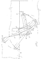
Wie aus der Zeichnung ersichtlich, umfaßt der veranschaulichte Vorrats- bzw. Lagerbehälter für Kleinteile, insbesondere Werkzeuge einen Boden 1, eine Rückwand 2, die auf nicht näher veranschaulichte Weise mit Aufhängemitteln versehen ist, um den Behälter in geöffnetem Zustand an einer Wand festlegen zu können, zwei Seitenwände 3, eine Deckwand 4, einen Vorderwandklappteil 5, der mit einem den vorderen Bereich der Deckwand 4 bildenden Deckwandklappteil 6 und seitlichen Endteilen 7, die die Seitenwände 3 ergänzen, verbunden ist. Dieser Vorderwandklappteil 5 ist aus einer Schließstellung, wie sie in Fig. 1 veranschaulicht ist, um eine zur Rückwand 2 parallele Schwenkachse um 180° in die in Fig. 2 veranschaulichte Öffnungsstellung, und umgekehrt, schwenkbar gelagert. Oberhalb der Deckwand 4 befindet sich ein Tragegriff 8, der sich in Behälterlängsrichtung erstreckt und unabhängig davon, ob sich die Deckwandklappteil-Vorderwandklappteil-Einheit in Öffnungs- oder in Schließstellung befindet, erfaßbar ist. Zwischen den seitlichen Endteilen 7 der Deckwandklappteil-Vorderwandklappteil-Einheit 5, 6 und der zugehörigen Seitenwand 3 ist jeweils eine Lenkeranordnung 9 vorgesehen, die das Verschwenken um 180° ermöglicht. Diese Lenkeranordnung 9 umfaßt einen Fixierpunkt 10 für jeweils eines der beiden Enden des sich über die ganze Behälterlänge erstreckenden Tragegriffs 8. Mit Hilfe der Lenkeranordnung 9 ist die Deckwandklappteil-Vorderwandklappteil-Einheit 5, 6 um den Tragegriff 7 herum aus der Schließ- in die Öffnungsstellung, und umgekehrt, verschwenkbar. Dies ergibt sich im einzelnen aus den Fig. 3 bis 5, die die Lenkeranordnung in größerem Maßstab zeigen.As can be seen from the drawing, the illustrated storage or storage container for small parts, in particular tools, comprises a base 1, a
Wie ersichtlich, umfaßt jede Lenkeranordnung zur Zwangssteuerung der Position des Tragegriffs 8 relativ zur Seitenwand 3 bzw. zum seitlichen Endteil 7 während des Verschwenkens einen mit seinem einen Ende am seitlichen Endteil angelenkten Grifflenker 11. An diesem greift einerseits ein erster Koppellenker 12 an, der mit der Seitenwand 3 gelenkig verbunden ist. Andererseits ist ein ebenfalls mit der Seitenwand 7 gelenkig verbundener Steuerlenker 13 vorgesehen, der über einen zweiten Koppellenker 14 an das seitliche Endteil 7 schwenkbar angeschlossen ist. Der Grifflenker 11 ist mit einem über den Gelenkpunkt 15, an dem der Steuerlenker 13 angreift, vorstehenden Abschnitt 16 versehen, an dessen freiem Ende der Fixierpunkt 10 für den Tragegriff vorgesehen ist. Den Figuren ist entnehmbar, daß der erste Koppellenker 12 im Bereich des vorstehenden Abschnitts 16 des Grifflenkers 11 angelenkt ist, genauer gesagt, die Anlenkstelle des ersten Koppellenkers 12 in Bezug auf den Grifflenker 11 ist am Fixierpunkt 10 für den Tragegriff vorgesehen.As can be seen, each link arrangement for the forced control of the position of the
Ferner ergibt sich aus der Zeichnung, daß der erste Koppellenker 12 über einen Koppellenkerträger 17 mit der Seitenwand 3 verbunden ist, der über den oberen Rand der Seitenwand 3 vorsteht.It also follows from the drawing that the
Aus den die Lenkeranordnung in größerem Maßstab zeigenden Fig. 3 bis 5 geht auch hervor, an welchen Stellen und mit welchen relativen Abmessungen die Koppellenker 12, 14 sowie der Steuerlenker 13 in Bezug auf den Grifflenker 11 ausgebildet und angeordnet sind. So zeigt Fig. 5, daß der Grifflenker 11 derart am seitlichen Endteil 7 unmittelbar sowie mittelbar über so bemessene und festgelegte Koppellenker 12, 14 und Steuerlenker 13 an der Seitenwand 3 angelenkt ist, daß er in Schließstellung zusammen mit dem ersten Koppellenker 12 eine etwa gestreckte Lage einnimmt. In dieser Position ist der Abstand al des Fixierpunkts 10 für den Tragegriff 8 von der Rückwandebene größer als der entsprechende Abstand a2 nach Überführung in die Öffnungsstellung, vgl. Fig. 3, in der der Grifflenker 11 und der erste Koppellenker 12 eine zusammengeklappte Lage einnehmen.3 to 5 also show at which locations and with what relative dimensions the coupling links 12, 14 and the control link 13 are designed and arranged in relation to the handlebars 11. Thus, Fig. 5 shows that the
In den Fig. 3 bis 5 ist der Übersichtlichkeit halber der Steuerlenker 13 in Form eines stumpfwinkligen Dreiecks dargestellt in dessen Eckpunkten sich die Gelenkpunkte für die Festlegung an der Seitenwand 3 bzw. für den Angriff des zweien Koppellenkers 14 oder aber des Grifflenkers 11 befinden. Die relative Lage dieser Gelenkpunkte in Bezug zueinander ist auch bei der praktischen Ausführung gemäß den Fig. 1 und 2 verwirklicht. Dort ist der Steuerlenker 13 jedoch in Form einer Scheibe ausgebildet. Diese ist so groß bemessen, daß sie einen Teil der Gelenkstellen sowie einen wesentlichen Teil der Koppel- und Grifflenker abdeckt.3 to 5, for the sake of clarity, the control link 13 is shown in the form of an obtuse-angled triangle, in the corner points of which the articulation points for fixing on the
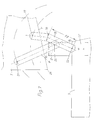
Bei der in den Fig. 6 und 7 veranschaulichten Ausführungsform ist an den beiden Seitenwänden 3 jeweils ein Griffträger 17' festgelegt, der wie der Koppellenkerträger 17 der ersten Ausführungsform über den oberen Rand der Seitenwand 3 vorsteht, jedoch bei dieser abgewandelten Ausführungsform an seinem oberen Ende selbst den Fixierpunkt 10 für den Tragegriff 8 aufweist. Außerdem umfaßt bei dieser Variante jede Lenkeranordnung 9 lediglich zwei Lenker, nämlich einen ersten Lenker 18 und einen zweiten Lenker 19. Der erste Lenker 18 ist einerseits am Griffträger 17' in der Nähe des Tragegriff-Fixierpunktes 10 und andererseits dicht über dem Deckwandklappteil 6 am seitlichen Endteil 7 angelenkt. Der zweite Lenker 19 ist in der in Fig. 6 veranschaulichten Öffnungsstellung des Behälters den ersten Lenker kreuzend einerseits im Bereich der Berührungsebene B von Deckwand 4 und Deckwandklappteil 6 nahe der Vorderkante 4' der Deckwand 4 und andererseits am seitlichen Endteil 7 nahe der Vorderkante 7' des seitlichen Endteils 7 jedoch mit vergleichsweise größerem Abstand von der Berührungsebene B von Deckwand 4 und Deckwandklappteil 6 angelenkt.In the embodiment illustrated in FIGS. 6 and 7 there is one on each of the two
Die Abstände b1 und b2 der Anlenkstellen 20, 21 bzw. 22, 23 jedes der beiden Lenker 18 bzw. 19 sind, wie der Zeichnung leicht entnommen werden kann, etwa gleich groß. Ebenso verdeutlicht die Zeichnung, daß der Abstand b3 der Anlenkstelle 21 des ersten Lenkers 18 am seitlichen Endteil 7 von der Anlenkstelle 23 des zweiten Lenkers 19 am seitlichen Endteil 7 etwa 3/4 des Abstandes b1 der Anlenkstellen 20 und 21 des ersten Lenkers 18 bzw. der Anlenkstellen 22 und 23 des zweiten Lenkers 19 voneinander beträgt.The distances b1 and b2 of the articulation points 20, 21 and 22, 23 of each of the two
Die im Bereich der Berührungsebene B von Deckwand 4 und Deckwandklappteil 6 befindliche Anlenkstelle 22 des zweiten Lenkers 19 ist in der Mitte zwischen der oberen Vorderkante 24 der Seitenwand 3 und der unteren Vorderkante 25 des seitlichen Endteils 7 vorgesehen. Der Abstand b4 der Anlenkstelle 21 des ersten Lenkers 18 von der Berührungsebene B von Deckwand 4 und Deckwandklappteil 6 einerseits und der Abstand b5 der Anlenkstelle 23 des zweiten Lenkers 19 von der Vorderkante 7' des seitlichen Endteils 7 andererseits sind etwa gleich groß bemessen. Diese Abstände b4 bzw. b5 betragen knapp 1/5 des Abstandes b1 bzw. b2 der Anlenkstellen 20 und 21 des ersten Lenkers 18 bzw. der Anlenkstellen 22 und 23 des zweiten Lenkers 19 voneinander.The
Wie aus der Zeichnung ferner hervorgeht, weist der zweite Lenker 19 in dem Bereich mit dem er bei Verschwenkung das äußere Ende des Griffträgers 17' passiert, eine Abwinkelung auf. In diesem mit einer Wellenlinie 26 näher bezeichneten Bereich ist das zur Anlenkstelle 23 führende Lenkerende nämlich, um der Stärke des Materials des Griffträgers 17' und des ersten Lenkers 18 Rechnung zu tragen gegenüber dem zur Anlenkstelle 22 führenden Lenkerende abgekröpft.As can also be seen from the drawing, the
Analog zur ersten Ausführungsform, bei der der Steuerlenker 13 in Form einer Scheibe ausgebildet ist, vgl. Fig. 1 und 2, kann bei der abgewandelten Ausführung der zweite Lenker 19 zumindest teilweise scheibenförmig ausgeführt sein, und zwar zweckmäßigerweise mit einem Radius einer Länge, die dem Abstand b6 zwischen der Anlenkstelle 22 und dem die Abkröpfung aufweisenden Bereich 26 entspricht.Analogous to the first embodiment, in which the control link 13 is in the form of a disc, cf. 1 and 2, in the modified embodiment, the
Selbstverständlich ist der Behälter in seinem Inneren mit üblichen Ablagebrettern oder -Vorrichtungen für die sichere geordnete Unterbringung der Kleinteile, im Falle eines Werkzeugkasten mit Mitteln zur Halterung der verschiedenen Werkzeuge nebst Zubehör versehen. Der Übersichtlichkeit halber wurde die Innenausstattung des Behältes jedoch nicht dargestellt.Of course, the inside of the container is provided with conventional storage boards or devices for the safe, orderly storage of small parts, in the case of a tool box with means for holding the various tools and accessories. For the sake of clarity, the interior of the container has not been shown.
Claims (13)
- Portable supplies and/or storage container of substantially cuboid shape for hardware, more particularly tools, comprising a floor (1), a back wall (2) which may be fitted with suspension means if appropriate, two side walls (3), a top wall (4), a folding front wall panel (5) which is joined to a folding top wall panel (6) constituting the front portion of the top wall and to lateral end panels (7) which complete the side walls (3), and which is mounted so as to swivel through 180° out of a shut position and into the open position about a swivel axis parallel with the back wall, and vice versa, and further comprising, arranged above the base panel of the top wall, a carrying handle (8) which extends lengthways along the container and is designed to be gripped irrespective of whether the unit (5, 6) comprising the folding top wall panel and the folding front wall panel is in the open or the shut position,
characterised in that between the lateral end panels (7) of the unit (5, 6) comprising the folding top wall panel and folding front wall panel and the associated side wall (3) is arranged a respective linkage arrangement (9) allowing 180° swivel, which includes a respective locating point (10) for each of the two ends of the carrying handle (8) extending the entire length of the container, and with the aid of which linkage arrangement the unit (5, 6) comprising the folding top wall panel and folding front wall panel can be swivelled around the carrying handle (8) out of the shut position and into the open position, and vice versa. - Container according to claim 1, characterised in that for positive control of the position of the carrying handle (8) in relation to the side wall (3) or lateral end panel (7) during the swivelling movement, each linkage arrangement (9) includes a handle linkage (11) hinged by one end to the lateral end panel, and on the one hand a first coupling linkage (12) pivoting on the side wall (3) engages said handle linkage (11), and on the other hand a control linkage (13) likewise pivoting on the side wall is attached to the lateral end panel (7) via a second coupling linkage (14) in a manner allowing it to swivel.
- Container according to claim 1 or 2, characterised in that the handle linkage (11) incorporates a section (16) which projects beyond the fulcrum point (15) at which the control linkage (13) acts, and the locating point (10) for the carrying handle (8) is provided on the free end of said section (16).
- Container according to any of claims 1 to 3, characterised in that the first coupling linkage (12) is hinged in the vicinity of the projecting section (16) of the handle linkage (11).
- Container according to any of claims 1 to 4, characterised in that the hinge point of the first coupling linkage (12) relating to the handle linkage (11) is provided at the locating point (10) for the carrying handle (8).
- Container according to any of claims 1 to 5, characterised in that the first coupling linkage (12) is connected to the side wall (3) via a coupling linkage bracket (17) located on the side wall (3) and projecting beyond the top edge thereof.
- Container according to any of claims 1 to 6, characterised in that the handle linkage (11) is hinged in such a way to the lateral end panel (7) directly and indirectly via coupling linkages (12, 14) and control linkages (13) so dimensioned and located that in the shut position said handle linkage (11) together with the first coupling linkage (12) assumes a somewhat elongated position in which the distance (a1) of the locating point (10) for the carrying handle (8) from the plane of the back wall is greater than the corrresponding distance (a2) after conversion to the open position, in which the handle linkage (11) and the first coupling linkage (12) assume a collapsed position.
- Container according to any of claims 1 to 7, characterised in that the control linkage (13) is in the form of a plate large enough to cover some of the fulcrum points.
- Container according to claim 1, characterised in that on each of the two side walls (3) is located a handle bracket (17') which projects beyond the top edge of said side walls and incorporates the locating point (10) for the carrying handle (8), and in that the two linkage arrangements (9) respectively associated with the side walls (3) each include only two linkages (18, 19), of which the first (18) in each case is hinged on the one hand on the handle bracket (17') close to the carrying handle locating point (10) and on the other hand closely above the folding top wall panel (6) on the lateral end panel (7), and of which the second (19) in each case, with the container open, crosses the first linkage (18) and is hinged on the one hand in the vicinity of the contact plane (B) of the top wall (4) and the folding top wall panel (6) close to the front edge of the top wall (4), and on the other hand on the lateral end panel (7) close to the front edge (7') of the lateral end panel (7), but at a comparatively greater distance from the contact plane (B) of the top wall (4) and the folding top wall panel (6).
- Container according to claim 9, characterised in that the distances (b1, b2) between the hinge points (20, 21; 22, 23) of each of the two linkages (18, 19) are approximately identical.
- Container according to claim 10, characterised in that the distance (b3) from the hinge point (21) of the first linkage (18) on the lateral end panel (7) to the hinge point (23) of the second linkage (19) on the lateral end panel (7) is approximately 3/4 of the distance of the hinge points (20, 21) of the first linkage (18) and the hinge points (22, 23) of the second linkage (19) from each other.
- Container according to either of claims 9 and 10, characterised in that the hinge point (22) of the second linkage (19) situated in the vicinity of the contact plane (B) of the top wall (4) and the folding top wall panel (6) is situated at the centre between the upper front edge (24) of the side wall (3) and the lower front edge (25) of the lateral end panel (7).
- Container according to any of claims 10 to 12, characterised in that the distances (b4) of the hinge point (21) of the first linkage (18) from the contact plane (B) of the top wall (4) and the folding top wall panel (6), on the one hand, and of the hinge point (23) of the second linkage (19) from the front edge (7') of the lateral end panel (7), on the other hand, are approximately identical and preferably barely 1/5 of the distances (b1, b2) of the hinge points (20, 21) of the first linkage (18) and the hinge points (22, 23) of the second linkage (19) from each other.
Applications Claiming Priority (4)
| Application Number | Priority Date | Filing Date | Title |
|---|---|---|---|
| DE4004574 | 1990-02-14 | ||
| DE4004574 | 1990-02-14 | ||
| DE4024304A DE4024304A1 (en) | 1990-02-14 | 1990-07-31 | Rectangular portable tool box - is in two halves hinged together and with handle accessible irrespective of position of two halves |
| DE4024304 | 1990-07-31 |
Publications (2)
| Publication Number | Publication Date |
|---|---|
| EP0442479A1 EP0442479A1 (en) | 1991-08-21 |
| EP0442479B1 true EP0442479B1 (en) | 1993-07-28 |
Family
ID=25890119
Family Applications (1)
| Application Number | Title | Priority Date | Filing Date |
|---|---|---|---|
| EP91102036A Expired - Lifetime EP0442479B1 (en) | 1990-02-14 | 1991-02-13 | Transportable storage bin and/or tool-box, in particular for tools |
Country Status (5)
| Country | Link |
|---|---|
| EP (1) | EP0442479B1 (en) |
| AT (1) | ATE91942T1 (en) |
| DE (2) | DE4024304A1 (en) |
| DK (1) | DK0442479T3 (en) |
| ES (1) | ES2044627T3 (en) |
Cited By (1)
| Publication number | Priority date | Publication date | Assignee | Title |
|---|---|---|---|---|
| DE102010052398A1 (en) | 2010-06-28 | 2011-12-29 | Ulrich Witt | Grasp unit for transporting e.g. hand-held tools, has container horizontally provided with different positions and feeding opened lid flaps that are fixed by grasp unit, and facing props connected to frame structure |
Families Citing this family (2)
| Publication number | Priority date | Publication date | Assignee | Title |
|---|---|---|---|---|
| DE102004053524A1 (en) * | 2004-11-05 | 2006-05-11 | Wero-Medical, Werner Michallik Gmbh & Co Kg | Dressing container |
| US8534779B2 (en) | 2010-10-06 | 2013-09-17 | Kenneth Schaaf | Portable station |
Family Cites Families (7)
| Publication number | Priority date | Publication date | Assignee | Title |
|---|---|---|---|---|
| US1345247A (en) * | 1920-01-13 | 1920-06-29 | Orlando B Robbins | Combination tool-box and sawhorse |
| CH223471A (en) * | 1940-10-04 | 1942-09-15 | Kron Karl | Single-sided hinge band. |
| FR1076887A (en) * | 1953-05-13 | 1954-11-02 | Chambonne | Device allowing the removal of the handle bar of tool boxes with several compartments, after deployment of the compartments |
| DE3210721A1 (en) * | 1982-03-24 | 1983-10-06 | Kueffner Reinhold Innenausbau | HINGE FITTING FOR BUILDING AND FURNITURE DOORS, OR -WINDOW |
| FR2573636B1 (en) * | 1984-11-29 | 1987-02-13 | Payen Raoul | SHELVING SUITCASE |
| DE3507953A1 (en) * | 1985-03-06 | 1986-09-18 | Alfred 8910 Landsberg Weber | TOOLBOX |
| US4613041A (en) * | 1985-06-18 | 1986-09-23 | Carlton Robert E | Portable storage kit for household cleansers |
-
1990
- 1990-07-31 DE DE4024304A patent/DE4024304A1/en not_active Withdrawn
-
1991
- 1991-02-13 ES ES91102036T patent/ES2044627T3/en not_active Expired - Lifetime
- 1991-02-13 AT AT91102036T patent/ATE91942T1/en not_active IP Right Cessation
- 1991-02-13 DE DE9191102036T patent/DE59100211D1/en not_active Expired - Fee Related
- 1991-02-13 DK DK91102036.0T patent/DK0442479T3/en active
- 1991-02-13 EP EP91102036A patent/EP0442479B1/en not_active Expired - Lifetime
Cited By (1)
| Publication number | Priority date | Publication date | Assignee | Title |
|---|---|---|---|---|
| DE102010052398A1 (en) | 2010-06-28 | 2011-12-29 | Ulrich Witt | Grasp unit for transporting e.g. hand-held tools, has container horizontally provided with different positions and feeding opened lid flaps that are fixed by grasp unit, and facing props connected to frame structure |
Also Published As
| Publication number | Publication date |
|---|---|
| DE4024304A1 (en) | 1991-08-22 |
| ATE91942T1 (en) | 1993-08-15 |
| DK0442479T3 (en) | 1993-12-27 |
| DE59100211D1 (en) | 1993-09-02 |
| ES2044627T3 (en) | 1994-01-01 |
| EP0442479A1 (en) | 1991-08-21 |
Similar Documents
| Publication | Publication Date | Title |
|---|---|---|
| DE4327869C1 (en) | Parcel shelf with closing flap and folding table arranged thereon | |
| CH683838A5 (en) | Container. | |
| EP1884438B1 (en) | Wheeled container for piece goods | |
| DE2729767C2 (en) | Arrangement for storing skis and accessories | |
| EP0141398B1 (en) | Nestable shopping trolley | |
| EP0442479B1 (en) | Transportable storage bin and/or tool-box, in particular for tools | |
| DE2614906A1 (en) | Swivelling support for waste container - is built into cupboard unit and fitted with coordinated cover | |
| DE3902277C1 (en) | ||
| EP0011297B1 (en) | Container, especially a refuse container, with a pivotable sliding lid for the anterior part and a second lid for the posterior part of the container opening | |
| EP1354824B1 (en) | Kit for a refuse receptacle with plug-in handles | |
| EP0633101B1 (en) | Cassette for the storage of articles | |
| DE10202058C1 (en) | Switch cabinet has opening door supported by hinge axis held between hinge lugs projecting beyond front vertical ends of sidewalls | |
| DE3511955C2 (en) | ||
| AT401547B (en) | HINGE | |
| EP0308713B1 (en) | Shopping trolley | |
| CH624638A5 (en) | Rubbish container | |
| EP0338341A2 (en) | Switchgear cabinet with hinged frame | |
| DE7811011U1 (en) | FLAP FITTING | |
| DE2854706C2 (en) | Device for holding a garbage container | |
| DE1299382B (en) | Saucepan with removable lid | |
| DE2914326C2 (en) | Device for holding a garbage container | |
| DE3304656A1 (en) | LIFTING AND TILTING DEVICE FOR LARGE VOLUME HINGED COVER TANK | |
| DE19821408A1 (en) | Door closure for doors or loading walls has grip and support element | |
| DE19713297A1 (en) | Frame structure to hold sacks open | |
| DE1753117C3 (en) | Vending machine door |
Legal Events
| Date | Code | Title | Description |
|---|---|---|---|
| PUAI | Public reference made under article 153(3) epc to a published international application that has entered the european phase |
Free format text: ORIGINAL CODE: 0009012 |
|
| AK | Designated contracting states |
Kind code of ref document: A1 Designated state(s): AT BE CH DE DK ES FR GB IT LI NL SE |
|
| 17P | Request for examination filed |
Effective date: 19910821 |
|
| 17Q | First examination report despatched |
Effective date: 19921207 |
|
| GRAA | (expected) grant |
Free format text: ORIGINAL CODE: 0009210 |
|
| AK | Designated contracting states |
Kind code of ref document: B1 Designated state(s): AT BE CH DE DK ES FR GB IT LI NL SE |
|
| REF | Corresponds to: |
Ref document number: 91942 Country of ref document: AT Date of ref document: 19930815 Kind code of ref document: T |
|
| REF | Corresponds to: |
Ref document number: 59100211 Country of ref document: DE Date of ref document: 19930902 |
|
| ITF | It: translation for a ep patent filed |
Owner name: ING. C. GREGORJ S.P.A. |
|
| GBT | Gb: translation of ep patent filed (gb section 77(6)(a)/1977) |
Effective date: 19931101 |
|
| ET | Fr: translation filed | ||
| REG | Reference to a national code |
Ref country code: DK Ref legal event code: T3 |
|
| REG | Reference to a national code |
Ref country code: ES Ref legal event code: FG2A Ref document number: 2044627 Country of ref document: ES Kind code of ref document: T3 |
|
| PLBE | No opposition filed within time limit |
Free format text: ORIGINAL CODE: 0009261 |
|
| STAA | Information on the status of an ep patent application or granted ep patent |
Free format text: STATUS: NO OPPOSITION FILED WITHIN TIME LIMIT |
|
| 26N | No opposition filed | ||
| EAL | Se: european patent in force in sweden |
Ref document number: 91102036.0 |
|
| PGFP | Annual fee paid to national office [announced via postgrant information from national office to epo] |
Ref country code: SE Payment date: 19980127 Year of fee payment: 8 |
|
| PGFP | Annual fee paid to national office [announced via postgrant information from national office to epo] |
Ref country code: DK Payment date: 19980220 Year of fee payment: 8 |
|
| PGFP | Annual fee paid to national office [announced via postgrant information from national office to epo] |
Ref country code: BE Payment date: 19980223 Year of fee payment: 8 |
|
| PGFP | Annual fee paid to national office [announced via postgrant information from national office to epo] |
Ref country code: ES Payment date: 19980416 Year of fee payment: 8 |
|
| PG25 | Lapsed in a contracting state [announced via postgrant information from national office to epo] |
Ref country code: SE Free format text: LAPSE BECAUSE OF NON-PAYMENT OF DUE FEES Effective date: 19990214 |
|
| PG25 | Lapsed in a contracting state [announced via postgrant information from national office to epo] |
Ref country code: ES Free format text: LAPSE BECAUSE OF NON-PAYMENT OF DUE FEES Effective date: 19990215 |
|
| PG25 | Lapsed in a contracting state [announced via postgrant information from national office to epo] |
Ref country code: BE Free format text: LAPSE BECAUSE OF NON-PAYMENT OF DUE FEES Effective date: 19990228 |
|
| PG25 | Lapsed in a contracting state [announced via postgrant information from national office to epo] |
Ref country code: DK Free format text: LAPSE BECAUSE OF NON-PAYMENT OF DUE FEES Effective date: 19990301 |
|
| BERE | Be: lapsed |
Owner name: ENTHOLZNER HANS-PETER Effective date: 19990228 |
|
| EUG | Se: european patent has lapsed |
Ref document number: 91102036.0 |
|
| PGFP | Annual fee paid to national office [announced via postgrant information from national office to epo] |
Ref country code: GB Payment date: 20000203 Year of fee payment: 10 |
|
| REG | Reference to a national code |
Ref country code: DK Ref legal event code: EBP |
|
| PGFP | Annual fee paid to national office [announced via postgrant information from national office to epo] |
Ref country code: NL Payment date: 20000229 Year of fee payment: 10 |
|
| PGFP | Annual fee paid to national office [announced via postgrant information from national office to epo] |
Ref country code: CH Payment date: 20000308 Year of fee payment: 10 |
|
| PGFP | Annual fee paid to national office [announced via postgrant information from national office to epo] |
Ref country code: AT Payment date: 20010126 Year of fee payment: 11 |
|
| PG25 | Lapsed in a contracting state [announced via postgrant information from national office to epo] |
Ref country code: GB Free format text: LAPSE BECAUSE OF NON-PAYMENT OF DUE FEES Effective date: 20010213 |
|
| PGFP | Annual fee paid to national office [announced via postgrant information from national office to epo] |
Ref country code: FR Payment date: 20010227 Year of fee payment: 11 |
|
| PG25 | Lapsed in a contracting state [announced via postgrant information from national office to epo] |
Ref country code: CH Free format text: LAPSE BECAUSE OF NON-PAYMENT OF DUE FEES Effective date: 20010228 Ref country code: LI Free format text: LAPSE BECAUSE OF NON-PAYMENT OF DUE FEES Effective date: 20010228 |
|
| REG | Reference to a national code |
Ref country code: ES Ref legal event code: FD2A Effective date: 20010503 |
|
| PG25 | Lapsed in a contracting state [announced via postgrant information from national office to epo] |
Ref country code: NL Free format text: LAPSE BECAUSE OF NON-PAYMENT OF DUE FEES Effective date: 20010901 |
|
| REG | Reference to a national code |
Ref country code: CH Ref legal event code: PL |
|
| GBPC | Gb: european patent ceased through non-payment of renewal fee |
Effective date: 20010213 |
|
| NLV4 | Nl: lapsed or anulled due to non-payment of the annual fee |
Effective date: 20010901 |
|
| PG25 | Lapsed in a contracting state [announced via postgrant information from national office to epo] |
Ref country code: AT Free format text: LAPSE BECAUSE OF NON-PAYMENT OF DUE FEES Effective date: 20020213 |
|
| PG25 | Lapsed in a contracting state [announced via postgrant information from national office to epo] |
Ref country code: FR Free format text: LAPSE BECAUSE OF NON-PAYMENT OF DUE FEES Effective date: 20021031 |
|
| REG | Reference to a national code |
Ref country code: FR Ref legal event code: ST |
|
| PG25 | Lapsed in a contracting state [announced via postgrant information from national office to epo] |
Ref country code: IT Free format text: LAPSE BECAUSE OF NON-PAYMENT OF DUE FEES Effective date: 20050213 |
|
| PGFP | Annual fee paid to national office [announced via postgrant information from national office to epo] |
Ref country code: DE Payment date: 20060118 Year of fee payment: 16 |
|
| PG25 | Lapsed in a contracting state [announced via postgrant information from national office to epo] |
Ref country code: DE Free format text: LAPSE BECAUSE OF NON-PAYMENT OF DUE FEES Effective date: 20070901 |