EP0441846B1 - Vorrichtung zum reduzieren des strömungswiderstandes im heckbereich eines fahrzeugs, z.b. eines strassen-oder schienenfahrzeugs oder dergleichen - Google Patents
Vorrichtung zum reduzieren des strömungswiderstandes im heckbereich eines fahrzeugs, z.b. eines strassen-oder schienenfahrzeugs oder dergleichen Download PDFInfo
- Publication number
- EP0441846B1 EP0441846B1 EP89912395A EP89912395A EP0441846B1 EP 0441846 B1 EP0441846 B1 EP 0441846B1 EP 89912395 A EP89912395 A EP 89912395A EP 89912395 A EP89912395 A EP 89912395A EP 0441846 B1 EP0441846 B1 EP 0441846B1
- Authority
- EP
- European Patent Office
- Prior art keywords
- vehicle
- openings
- air
- blow
- accordance
- Prior art date
- Legal status (The legal status is an assumption and is not a legal conclusion. Google has not performed a legal analysis and makes no representation as to the accuracy of the status listed.)
- Expired - Lifetime
Links
Images

Classifications
-
- B—PERFORMING OPERATIONS; TRANSPORTING
- B61—RAILWAYS
- B61D—BODY DETAILS OR KINDS OF RAILWAY VEHICLES
- B61D17/00—Construction details of vehicle bodies
- B61D17/02—Construction details of vehicle bodies reducing air resistance by modifying contour ; Constructional features for fast vehicles sustaining sudden variations of atmospheric pressure, e.g. when crossing in tunnels
-
- B—PERFORMING OPERATIONS; TRANSPORTING
- B62—LAND VEHICLES FOR TRAVELLING OTHERWISE THAN ON RAILS
- B62D—MOTOR VEHICLES; TRAILERS
- B62D35/00—Vehicle bodies characterised by streamlining
-
- Y—GENERAL TAGGING OF NEW TECHNOLOGICAL DEVELOPMENTS; GENERAL TAGGING OF CROSS-SECTIONAL TECHNOLOGIES SPANNING OVER SEVERAL SECTIONS OF THE IPC; TECHNICAL SUBJECTS COVERED BY FORMER USPC CROSS-REFERENCE ART COLLECTIONS [XRACs] AND DIGESTS
- Y02—TECHNOLOGIES OR APPLICATIONS FOR MITIGATION OR ADAPTATION AGAINST CLIMATE CHANGE
- Y02T—CLIMATE CHANGE MITIGATION TECHNOLOGIES RELATED TO TRANSPORTATION
- Y02T30/00—Transportation of goods or passengers via railways, e.g. energy recovery or reducing air resistance
Definitions
- the invention relates to a device for reducing the flow resistance in the rear area of a vehicle, for. B. a road or rail vehicle.
- the crucial area in which these undesirable currents are particularly evident is the entire rear area of a vehicle. It is known that the largest part of the flow resistance z. B. a motor vehicle is the pressure resistance, for example in a modern passenger car more than that Can make up six times the proportion of frictional resistance. This pressure resistance is largely determined by the detached, highly turbulent flow area, the so-called dead water area, in the rear area of the vehicle.
- a flow brake for high-speed motor vehicles has become known from German patent specification No. 649 343, which provides that air blown out in the longitudinal direction of the vehicle is extracted in the rear region of a vehicle.
- the author of this patent specification wants to use these measures to slow the vehicle down.
- the invention is based on the development of a device in which air in the rear area of a vehicle is blown out and extracted again in such a way that an efficient reduction in the overall resistance of the vehicle is achieved.
- This object is achieved by claim 1, advantageous developments of the invention result from the associated subclaims.
- the "Coanda effect” is understood to mean the property of fluid jets (liquid or gas jets) to apply to and flow along solid walls located nearby, the fluid jet emerging from its original. Direction of propagation is deflected.
- This Coanda effect is used in conjunction with a targeted blowing out of air in the area of the release line (s) of the rear of the vehicle, and that at a relatively high speed, so that the flow builds up along a curved surface which is flowed towards or around. Finally, the air is sucked out of the dead water area again, whereby the combination of measures achieves the desired overall effect, ie the total Bernoullic pressure in the rear area is increased and, as a result, the pressure resistance and thus the total Flow resistance reduced or minimized to a sufficient extent.
- the speed of the blown out air jets is set sufficiently high, in particular up to approx. 50 m / sec. H. higher than the ambient speed so that the Coanda effect can be used properly. This can be promoted in that the air is guided in a regulated or controlled air circuit.
- 1-3 is based on the assumption that a car 1 moves forward on a road and is exposed to an external flow 2.
- FIG. 1 is designed as a hatchback model, in which in particular in the area of a vehicle rear 3, i. H. in other words, a dead water area 4 occurs practically behind this vehicle rear 3, d. H. a strongly swirled flow area in the rear area of the car 1.
- FIG. 2 shows a car 1 in the form of a notchback model
- FIG. 3 shows a car 1 in the form of a full-tail model, both of which also in the Corresponding dead water areas 4 are available at the rear.
- this dead water area 4 is characterized by a detachment line 5 which extends over the top and bottom and the side areas of the rear of the vehicle 3 and which indicates the beginning of the dead water and the large energy dissipation, i.e. h Conversion of kinetic flow energy into heat, defined. Due to the detachment and the energy dissipation, the static pressure in the dead water area 4 will not increase further and will remain almost constant. As a result this creates a large pressure resistance and thus a correspondingly large flow resistance of the respective vehicle.
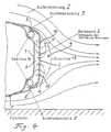
- a rear area of a car 1 is now shown schematically in a sectional view, this rear area now having a device for increasing the reduction in pressure resistance.
- first openings 9 in the form of blow-out slots which serve to blow out air at high speed, are arranged in particular in the region of release lines 5 of the rear of the vehicle 3. H. So to the so-called boundary layer blowing.
- an outer wall 6 of the rear of the vehicle 3 adjoining the dead water area 4 is designed and shaped such that the blown-out air is deflected from its original flow direction into the dead water area 4 using the Coanda effect, as indicated by arrows 12.
- both the first openings 9 and the second openings 10 are each designed in the form of bores or slots or the like.
- the first openings 9 are designed as elongated blow-out slots, which are located on the upper and lower edge areas of the rear drop side 6, ie in each case in the area the release lines 5 are arranged.
- the second openings 9, that is to say the suction openings are designed in the form of bores or holes which are arranged distributed over the surface of the rear drop side 6.
- two fans 11, preferably in the form of cross-flow fans, are arranged, which provide the necessary energy to blow out the boundary layer and extract the boundary layer to guarantee.
- These two blowers 11 are arranged in the vicinity of the first openings or blow-out slots 9 and thus serve on the one hand to convey the blow-out air through the first openings 9 and on the other hand to feed the exhaust air through the second openings 10 into the interior of the intermediate space 8.
- the fans 11 in the form of cross-flow fans are preferably adapted to the respective slot length of the first openings or blow-out slots 9.
- blowers 11 which is not shown in FIG. 4 for the sake of simplicity, electric motors are provided which are connected to the electrical system of the car 1 and are preferably flanged to the side of the blowers 11.
- the blower 11 When the blower 11 is started up, air is thus passed through the first openings or blow-out slots 9 in the region of the separation lines 5 at a high speed of approximately 50m / sec. blown out. As a result, kinetic energy is supplied to the strongly delayed boundary layer and detachment is initially avoided. The pressure in the area of the rear of the vehicle 3 can thus increase further. In addition, the air emerging from the blow-out slots 9 is deflected from the original tangential direction into the dead water area 4 on the subsequent rounded wall area of the outer wall or rear drop side 6 using the Coanda effect. In a preferred manner, the ratio of the height of a blow-out slot 9 to the radius of curvature of the rounded wall section of the outer wall 6 is substantially smaller than 1.
- This Coanda effect deflection also supplies the dead water area 4 with energy and the healthy outer flow 2 with high kinetic energy into the Steered rear area.
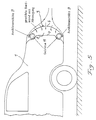
- FIG. 5 of a device for reducing the flow resistance in the rear area of a vehicle is modified compared to the embodiment according to FIG. 4 in that the outer wall 6 of the rear of the vehicle 3 of a notchback car 1, i. h So the rear drop side, in its area, which adjoins the upper and lower blow-out slots 9, is convexly curved outwards.
- an outwardly arched tailgate 6 results in a further streamlined effect, since this convex curvature does not result in such a strong deflection of the external flow, as a result of which the required blowing and suction performance and thus the performance of the blowers 11 can be reduced.
- an outward arched tailgate accommodates an improved design of the body shape in the rear area.
- the blowers 11 arranged in the space 8 between the outer wall 6 and the inner wall 7 of the rear of the vehicle are each designed as cross-flow blowers, which are installed over the entire slot lengths of the blow-out slots 9 and because of their small transverse dimensions and their high pressure figures are very beneficial.
- These cross flow fans which are used practically for the supply of energy, suck in the air in the same way, as shown in FIG. 4, through suction openings or bores in the convexly curved outer wall 6 or rear drop side of the vehicle rear 3 and then blow the air through the two blowout slots 9 in the area the release lines of the rear of the vehicle 3 at high speed (approx. 50m / sec.) (boundary layer blowing).
- blower drive by means of an exhaust gas turbine installed in the motor vehicle, with which the blower is then coupled.
- an exhaust gas turbocharger is coupled directly to the device according to the invention for the supply of energy, that is to say for the promotion of the exhaust air and the exhaust air, instead of fans.
- energy that is to say for the promotion of the exhaust air and the exhaust air, instead of fans.
- Such a solution is special obvious in the case of motor vehicles with rear-engine drive.
- part of the turbo useful power must be released to the environment via a bypass valve in order to avoid overstressing the engine due to excessive boost pressure.
- the full-load operation of the engine is now exactly the same as the high driving speed of the motor vehicle, in which the intended flow control by simultaneous blowing and suctioning and thus the reduction in resistance are most effective.
- the drive energy required to convey the blow-out and exhaust air i. H.
- the energy inserted into the device according to the invention is less than the energy saving as a result of the reduction in pressure resistance achieved in the rear area.
- first openings 9 are provided, which are designed in the form of blow-out slots, in particular with blowers 11 assigned to them. These blow-out slots are arranged both in the vertical and in the horizontal direction and thus surround the rear of the vehicle 3 in a quasi-annular manner.
- the method and the device according to the invention can be used with great advantage primarily in cars, trucks with box bodies and in buses, but also in rail vehicles, such as. B. high-speed trains.
- the device according to the invention is particularly effective in all vehicle designs with a "cut-off rear".
- boundary layer influencing consists in the coupling of the device according to the invention with the ventilation system of the passenger compartment or the connection of the suction or blow-out zones in the rear area with places on the body where high negative or positive pressures occur, e.g. B. in the wheel arch.
Landscapes
- Engineering & Computer Science (AREA)
- Mechanical Engineering (AREA)
- Chemical & Material Sciences (AREA)
- Combustion & Propulsion (AREA)
- Transportation (AREA)
- Body Structure For Vehicles (AREA)
- Structures Of Non-Positive Displacement Pumps (AREA)
Applications Claiming Priority (2)
| Application Number | Priority Date | Filing Date | Title |
|---|---|---|---|
| DE3837729A DE3837729A1 (de) | 1988-11-07 | 1988-11-07 | Verfahren und vorrichtung zum reduzieren des stroemungswiderstandes im heckbereich eines fahrzeugs, z. b. eines strassen- oder schienenfahrzeugs oder dergleichen |
| DE3837729 | 1988-11-07 |
Publications (2)
| Publication Number | Publication Date |
|---|---|
| EP0441846A1 EP0441846A1 (de) | 1991-08-21 |
| EP0441846B1 true EP0441846B1 (de) | 1994-03-09 |
Family
ID=6366650
Family Applications (1)
| Application Number | Title | Priority Date | Filing Date |
|---|---|---|---|
| EP89912395A Expired - Lifetime EP0441846B1 (de) | 1988-11-07 | 1989-11-07 | Vorrichtung zum reduzieren des strömungswiderstandes im heckbereich eines fahrzeugs, z.b. eines strassen-oder schienenfahrzeugs oder dergleichen |
Country Status (4)
| Country | Link |
|---|---|
| US (1) | US5407245A (enExample) |
| EP (1) | EP0441846B1 (enExample) |
| DE (2) | DE3837729A1 (enExample) |
| WO (1) | WO1990005084A1 (enExample) |
Families Citing this family (68)
| Publication number | Priority date | Publication date | Assignee | Title |
|---|---|---|---|---|
| DE9116515U1 (de) * | 1991-06-21 | 1993-01-21 | Daimler-Benz Aktiengesellschaft, 7000 Stuttgart | Vorrichtung zum Reduzieren des Strömungswiderstandes im Heckbereiche eines Fahrzeuges |
| US6616218B2 (en) * | 1994-10-19 | 2003-09-09 | The United States Of America As Represented By The Administrator Of The National Aeronautics And Space Administration | Base passive porosity for vehicle drag reduction |
| US6286892B1 (en) * | 1994-10-19 | 2001-09-11 | The United States Of America As Represented By The Administrator Of The National Aeronautics And Space Administration | Base passive porosity for drag reduction |
| IT1279132B1 (it) * | 1995-04-19 | 1997-12-04 | Dipartimento Di Energetica Del | Dispositivo per la riduzione della resistenza di forma dei veicoli. |
| US5908217A (en) * | 1995-07-17 | 1999-06-01 | Georgia Tech Research Corporation | Pneumatic aerodynamic control and drag-reduction system for ground vehicles |
| DE19602602A1 (de) * | 1996-01-25 | 1997-07-31 | Anton Dr Lechner | Vorrichtung zur Verringerung des Strömungswiderstandes eines Fahrzeuges, bevorzugt Nutzfahrzeuges |
| US6068328A (en) * | 1997-11-25 | 2000-05-30 | Gazdzinski; Robert F. | Vehicular boundary layer control system and method |
| DE19912140C2 (de) | 1999-03-18 | 2001-04-26 | Daimler Chrysler Ag | Kraftfahrzeug mit Strömungsbeeinflussungsmitteln zur Reduzierung des Luftwiderstandes |
| US6742616B2 (en) * | 2000-06-20 | 2004-06-01 | Michael F. Leban | Hybrid air boost vehicle and method for making same |
| DE10233041B4 (de) * | 2002-07-20 | 2006-04-20 | Daimlerchrysler Ag | Heckpartie eines Kraftfahrzeugs |
| SE0301352L (sv) * | 2003-05-09 | 2004-03-02 | Scania Cv Abp | Förfarande och anordning för styrning av luftmotstånd |
| US6994394B1 (en) * | 2003-05-23 | 2006-02-07 | Vitaliy Lyakir | Automobile body performing decreased aerodynamic lift |
| US7055638B2 (en) * | 2004-01-23 | 2006-06-06 | General Motors Corporation | Virtual airdam and method for a vehicle |
| FR2876975B1 (fr) * | 2004-10-25 | 2007-01-19 | Renault Sas | Methode et dispositif de controle des structures tourbillonnaires de sillage apparaissant aux parois des vehicules automobiles |
| US8940265B2 (en) * | 2009-02-17 | 2015-01-27 | Mcalister Technologies, Llc | Sustainable economic development through integrated production of renewable energy, materials resources, and nutrient regimes |
| SE528351C2 (sv) | 2005-01-27 | 2006-10-24 | Wm Data Caran Ab | Förbättringar av landfordons aerodynamiska egenskaper |
| ITBO20050457A1 (it) | 2005-07-08 | 2007-01-09 | Ferrari Spa | Vettura ad alte prestazioni con soffiaggio di aria per modificare il campo aerodinamico |
| DE102006019777A1 (de) * | 2006-04-28 | 2007-11-08 | Daimlerchrysler Ag | Kraftwagenheck |
| DE102006041955A1 (de) * | 2006-08-30 | 2008-03-20 | Deutsches Zentrum für Luft- und Raumfahrt e.V. | Verfahren zur Steuerung der Verbrennung in einer Brennkammer und Brennkammervorrichtung |
| US20080150321A1 (en) * | 2006-11-01 | 2008-06-26 | Colin Neale | Vehicle having aerodynamic fan elements |
| US7695050B2 (en) * | 2006-11-01 | 2010-04-13 | Colin Neale | Vehicle having aerodynamic fan elements |
| EP2162621B1 (en) | 2007-05-02 | 2012-06-06 | Ramot at Tel-Aviv University Ltd. | Apparatus and method for oscillating fluid jets |
| US8113466B2 (en) * | 2007-09-17 | 2012-02-14 | Birkenstock David T | System and method for drag reduction |
| US9188086B2 (en) * | 2008-01-07 | 2015-11-17 | Mcalister Technologies, Llc | Coupled thermochemical reactors and engines, and associated systems and methods |
| US8318131B2 (en) | 2008-01-07 | 2012-11-27 | Mcalister Technologies, Llc | Chemical processes and reactors for efficiently producing hydrogen fuels and structural materials, and associated systems and methods |
| US7810867B2 (en) * | 2008-04-14 | 2010-10-12 | Fastskinz, Inc. | Vehicle with drag-reducing outer surface |
| DE102008060257A1 (de) * | 2008-12-03 | 2010-06-10 | Daimler Ag | Aktive Grenzschichtbeeinflussung zur Minimierung des Luftwiderstandes eines Kraftwagens |
| US8313556B2 (en) * | 2009-02-17 | 2012-11-20 | Mcalister Technologies, Llc | Delivery systems with in-line selective extraction devices and associated methods of operation |
| US8980416B2 (en) * | 2009-02-17 | 2015-03-17 | Mcalister Technologies, Llc | Architectural construct having for example a plurality of architectural crystals |
| US9231267B2 (en) | 2009-02-17 | 2016-01-05 | Mcalister Technologies, Llc | Systems and methods for sustainable economic development through integrated full spectrum production of renewable energy |
| US8808529B2 (en) | 2009-02-17 | 2014-08-19 | Mcalister Technologies, Llc | Systems and methods for sustainable economic development through integrated full spectrum production of renewable material resources using solar thermal |
| US8441361B2 (en) | 2010-02-13 | 2013-05-14 | Mcallister Technologies, Llc | Methods and apparatuses for detection of properties of fluid conveyance systems |
| US9097152B2 (en) * | 2009-02-17 | 2015-08-04 | Mcalister Technologies, Llc | Energy system for dwelling support |
| US8814983B2 (en) | 2009-02-17 | 2014-08-26 | Mcalister Technologies, Llc | Delivery systems with in-line selective extraction devices and associated methods of operation |
| US8318269B2 (en) * | 2009-02-17 | 2012-11-27 | Mcalister Technologies, Llc | Induction for thermochemical processes, and associated systems and methods |
| WO2011100689A2 (en) | 2010-02-13 | 2011-08-18 | Mcalister Roy E | Chemical reactors with annularly positioned delivery and removal devices, and associated systems and methods |
| CA2789688C (en) * | 2010-02-13 | 2014-07-08 | Mcalister Technologies, Llc | Reactor vessels with pressure and heat transfer features for producing hydrogen-based fuels and structural elements, and associated systems and methods |
| AU2011216244A1 (en) * | 2010-02-13 | 2012-09-06 | Mcalister Technologies, Llc | Reactor vessels with transmissive surfaces for producing hydrogen-based fuels and structural elements, and associated systems and methods |
| US8662854B1 (en) | 2010-05-21 | 2014-03-04 | Fastskinz, Inc. | Turbine with turbulence inducing surface |
| US8734546B2 (en) | 2011-08-12 | 2014-05-27 | Mcalister Technologies, Llc | Geothermal energization of a non-combustion chemical reactor and associated systems and methods |
| US8826657B2 (en) | 2011-08-12 | 2014-09-09 | Mcallister Technologies, Llc | Systems and methods for providing supplemental aqueous thermal energy |
| WO2013025650A1 (en) | 2011-08-12 | 2013-02-21 | Mcalister Technologies, Llc | Mobile transport platforms for producing hydrogen and structural materials and associated systems and methods |
| US8669014B2 (en) | 2011-08-12 | 2014-03-11 | Mcalister Technologies, Llc | Fuel-cell systems operable in multiple modes for variable processing of feedstock materials and associated devices, systems, and methods |
| US9039327B2 (en) | 2011-08-12 | 2015-05-26 | Mcalister Technologies, Llc | Systems and methods for collecting and processing permafrost gases, and for cooling permafrost |
| US8888408B2 (en) | 2011-08-12 | 2014-11-18 | Mcalister Technologies, Llc | Systems and methods for collecting and processing permafrost gases, and for cooling permafrost |
| WO2013025644A1 (en) | 2011-08-12 | 2013-02-21 | Mcalister Technologies, Llc | Systems and methods for extracting and processing gases from submerged sources |
| WO2013025659A1 (en) | 2011-08-12 | 2013-02-21 | Mcalister Technologies, Llc | Reducing and/or harvesting drag energy from transport vehicles, includings for chemical reactors, and associated systems and methods |
| US8828491B2 (en) | 2011-08-12 | 2014-09-09 | Mcalister Technologies, Llc | Methods for manufacturing architectural constructs |
| US8673509B2 (en) | 2011-08-12 | 2014-03-18 | Mcalister Technologies, Llc | Fuel-cell systems operable in multiple modes for variable processing of feedstock materials and associated devices, systems, and methods |
| WO2013025655A2 (en) | 2011-08-12 | 2013-02-21 | Mcalister Technologies, Llc | Systems and methods for providing supplemental aqueous thermal energy |
| US8911703B2 (en) | 2011-08-12 | 2014-12-16 | Mcalister Technologies, Llc | Reducing and/or harvesting drag energy from transport vehicles, including for chemical reactors, and associated systems and methods |
| JP2013216247A (ja) * | 2012-04-10 | 2013-10-24 | Toyota Motor Corp | 車両後部構造 |
| US8926719B2 (en) | 2013-03-14 | 2015-01-06 | Mcalister Technologies, Llc | Method and apparatus for generating hydrogen from metal |
| US9534296B2 (en) | 2013-03-15 | 2017-01-03 | Mcalister Technologies, Llc | Methods of manufacture of engineered materials and devices |
| US9079489B2 (en) | 2013-05-29 | 2015-07-14 | Mcalister Technologies, Llc | Methods for fuel tank recycling and net hydrogen fuel and carbon goods production along with associated apparatus and systems |
| EP2851274B1 (en) * | 2013-09-23 | 2016-07-06 | C.R.F. Società Consortile per Azioni | System for controlling the aerodynamic drag of a motor-vehicle, adapted to cause separation of the boundary layer at a predetermined area of the motor-vehicle body, by the use of passive jets, and motor-vehicle provided with this system |
| DE102013219706A1 (de) * | 2013-09-30 | 2015-04-02 | Siemens Aktiengesellschaft | Anordnung zum zeitweiligen Erhöhen eines Luftwiderstands eines Schienenfahrzeugs |
| US8870275B1 (en) | 2013-10-18 | 2014-10-28 | Peter Schmidt | Active and passive boundary layer control for vehicle drag reduction |
| US9586632B2 (en) | 2014-11-14 | 2017-03-07 | Embry-Riddle Aeronautical University, Inc. | Optimizing jets for wake control of ground vehicles |
| DE102015004920A1 (de) * | 2015-04-17 | 2016-10-20 | Audi Ag | Vorrichtung zur Verringerung des Luftwiderstands eines Fahrzeugs |
| CN104960585A (zh) * | 2015-06-26 | 2015-10-07 | 哈尔滨工业大学深圳研究生院 | 基于射流激励器对汽车进行主动减阻控制的方法及系统 |
| US10933894B2 (en) * | 2016-04-16 | 2021-03-02 | Mircea Toma | System for loading and unloading moving vehicles |
| CN113401232B (zh) * | 2016-09-05 | 2023-05-16 | Ogab有限公司 | 一种主动减阻系统和减少车辆阻力的方法 |
| CN108313144A (zh) * | 2017-01-17 | 2018-07-24 | 郑州宇通客车股份有限公司 | 降低车辆风阻的方法、车辆气路系统及车辆 |
| WO2018163528A1 (ja) * | 2017-03-06 | 2018-09-13 | 株式会社ホンダアクセス | 自動車用空力部品 |
| CN109250002A (zh) * | 2017-07-13 | 2019-01-22 | 通用汽车环球科技运作有限责任公司 | 机动车辆的被动空气射流 |
| DE102018221976A1 (de) * | 2018-12-17 | 2020-06-18 | Psa Automobiles Sa | Luftwiderstandsverringerungseinrichtung für ein Fahrzeug und Verfahren zum Verringern des Luftwiderstands eines Fahrzeugs |
| EP4172029A4 (en) | 2020-06-24 | 2024-07-31 | Energy Horizon LLC | Land vehicle drag reduction device and method |
Family Cites Families (15)
| Publication number | Priority date | Publication date | Assignee | Title |
|---|---|---|---|---|
| DE539614C (de) * | 1927-08-21 | 1931-11-28 | Albert Betz Dr | Einrichtung zur Beeinflussung der Grenzschicht von einer Stroemung ausgesetzten Koerpern |
| US2242494A (en) * | 1932-04-07 | 1941-05-20 | Austin M Wolf | Ventilating and cooling system for motor vehicles |
| DE649343C (de) * | 1935-02-28 | 1937-08-31 | Waggon Fabrik A G | Stroemungsbremse fuer Schnellkraftfahrzeuge |
| US2037942A (en) * | 1935-10-28 | 1936-04-21 | Edward A Stalker | Means of reducing the fluid resistance of propelled vehicles |
| GB616163A (en) * | 1943-01-19 | 1949-01-18 | Groupement Francais Pour Le Developpement Des Recherches Aeronautiques | Means for avoid separation and turbulence in fluids moving with respect to solid surfaces |
| FR916198A (fr) * | 1944-10-28 | 1946-11-28 | Système réducteur de la résistance aérodynamique des mobiles | |
| FR1168556A (fr) * | 1957-02-07 | 1958-12-10 | Perfectionnements aux ailes d'avions | |
| DE1456066A1 (de) * | 1962-12-24 | 1970-01-08 | Hermann Papst | Anordnung zur Grenzschichtabsaugung bei Strassen- und Wasserfahrzeugen |
| US3591229A (en) * | 1967-07-14 | 1971-07-06 | Daimler Benz Ag | Installation for reducing the soiling of rear lights or the like at motor vehicle bodies |
| DE2212952A1 (de) * | 1972-03-17 | 1973-09-27 | Messerschmitt Boelkow Blohm | Schienenfahrzeug oder schienenzug, vorzugsweise fuer schnellbahnen |
| US4460055A (en) * | 1980-11-03 | 1984-07-17 | Karl Steiner | System to increase vehicle fuel efficiency |
| US4393852A (en) * | 1980-12-08 | 1983-07-19 | Eaton Corporation | Linkage mechanism for supercharger system |
| DE3230640A1 (de) * | 1982-08-18 | 1984-02-23 | Volkswagenwerk Ag, 3180 Wolfsburg | Fahrzeug mit relativ steil abfallendem heck |
| DE3230641A1 (de) * | 1982-08-18 | 1984-02-23 | Volkswagenwerk Ag, 3180 Wolfsburg | Fahrzeug mit relativ steil abfallendem heck |
| US5184832A (en) * | 1984-12-07 | 1993-02-09 | Tsutomu Miwa | Aerodynamic motorcar |
-
1988
- 1988-11-07 DE DE3837729A patent/DE3837729A1/de active Granted
-
1989
- 1989-11-07 US US07/679,053 patent/US5407245A/en not_active Expired - Fee Related
- 1989-11-07 EP EP89912395A patent/EP0441846B1/de not_active Expired - Lifetime
- 1989-11-07 WO PCT/DE1989/000702 patent/WO1990005084A1/de not_active Ceased
- 1989-11-07 DE DE89912395T patent/DE58907194D1/de not_active Expired - Fee Related
Also Published As
| Publication number | Publication date |
|---|---|
| DE3837729A1 (de) | 1990-05-10 |
| EP0441846A1 (de) | 1991-08-21 |
| WO1990005084A1 (de) | 1990-05-17 |
| US5407245A (en) | 1995-04-18 |
| DE58907194D1 (de) | 1994-04-14 |
| DE3837729C2 (enExample) | 1991-01-10 |
Similar Documents
| Publication | Publication Date | Title |
|---|---|---|
| EP0441846B1 (de) | Vorrichtung zum reduzieren des strömungswiderstandes im heckbereich eines fahrzeugs, z.b. eines strassen-oder schienenfahrzeugs oder dergleichen | |
| DE102013219894B4 (de) | Fahrzeug mit aktivem Luftdiffusor | |
| DE3617538C2 (enExample) | ||
| DE102016125656B4 (de) | Luftfahrzeug mit einem Kühlsystem und Kühlverfahren | |
| DE602004009503T2 (de) | System zur Reduzierung des Luftwiderstandes, und Kraftfahrzeug ausgerüstet mit einem derartigen System | |
| DE19602602A1 (de) | Vorrichtung zur Verringerung des Strömungswiderstandes eines Fahrzeuges, bevorzugt Nutzfahrzeuges | |
| DE19705268A1 (de) | Kraftfahrzeug mit einer bugseitigen Luftführungsvorrichtung | |
| DE69907054T2 (de) | Entlüftungsrohrauslass eines Getriebegehäuses | |
| EP0199010B1 (de) | Aerodynamische Vorrichtung für einen Personenwagen | |
| DE102016118692A1 (de) | Anpresskrafterzeugungssystem für ein Fahrzeug | |
| EP3075622B1 (de) | Fahrzeug mit einem an der fahrzeugoberfläche mündenden luftkanal | |
| DE102018113773A1 (de) | Fahrzeug-Kofferraumdeckelspoiler mit aerodynamisch geformten Flügelabschnitten | |
| DE29721562U1 (de) | Fahrzeug mit Mitteln zur Verringerung des heckseitig induzierten Luftwiderstandes | |
| DE102011121407A1 (de) | Diffusoranordnung | |
| DE102018004148A1 (de) | Anordnung einer Luftleiteinrichtung an einem Aufbau für ein Fahrzeug, insbesondere für ein Nutzfahrzeug, sowie Fahrzeug mit einer solchen Anordnung | |
| DE102019104285B4 (de) | Antennengehäuse mit Profilelement zur Windlastreduzierung | |
| DE102016215032A1 (de) | Luftleiteinrichtung für ein Kraftfahrzeug | |
| EP3386831B1 (de) | Eisenbahn-triebfahrzeug mit dachübergangselement | |
| WO2022033784A1 (de) | Unterbodenverkleidungselement für ein fahrzeug sowie anordnung einer unterbodenverkleidung an einem aufbau eines fahrzeugs | |
| DE102006025752A1 (de) | Verfahren und Vorrichtung zum Erzeugen von aerodynamischem Widerstand an einem Flugzeug | |
| DE1630335C3 (de) | Einrichtung zur Verminderung der Verschmutzung von Heckleuchten an Kraftfahrzeugkarosserien | |
| WO2018172207A1 (de) | System zur aerodynamischen verbesserung eines landfahrzeuges insbesondere von einem lkw oder ähnlichem | |
| CH391486A (de) | Luftführungseinrichtung an Kraftfahrzeugen | |
| DE102015012057A1 (de) | Spoilereinrichtung | |
| DE1630335B2 (de) | Einrichtung zur verminderung der verschmutzung von heckleuchten an kraftfahrzeugkarosserien |
Legal Events
| Date | Code | Title | Description |
|---|---|---|---|
| PUAI | Public reference made under article 153(3) epc to a published international application that has entered the european phase |
Free format text: ORIGINAL CODE: 0009012 |
|
| 17P | Request for examination filed |
Effective date: 19910504 |
|
| AK | Designated contracting states |
Kind code of ref document: A1 Designated state(s): DE FR GB IT SE |
|
| RAP1 | Party data changed (applicant data changed or rights of an application transferred) |
Owner name: DAIMLER-BENZ AKTIENGESELLSCHAFT |
|
| RIN1 | Information on inventor provided before grant (corrected) |
Inventor name: GEROPP, DIETER |
|
| RIN1 | Information on inventor provided before grant (corrected) |
Inventor name: GEROPP, DIETER, PROF.DR. |
|
| 17Q | First examination report despatched |
Effective date: 19920630 |
|
| RTI1 | Title (correction) | ||
| GRAA | (expected) grant |
Free format text: ORIGINAL CODE: 0009210 |
|
| ITF | It: translation for a ep patent filed | ||
| AK | Designated contracting states |
Kind code of ref document: B1 Designated state(s): DE FR GB IT SE |
|
| REF | Corresponds to: |
Ref document number: 58907194 Country of ref document: DE Date of ref document: 19940414 |
|
| GBT | Gb: translation of ep patent filed (gb section 77(6)(a)/1977) |
Effective date: 19940412 |
|
| ET | Fr: translation filed | ||
| PLBE | No opposition filed within time limit |
Free format text: ORIGINAL CODE: 0009261 |
|
| STAA | Information on the status of an ep patent application or granted ep patent |
Free format text: STATUS: NO OPPOSITION FILED WITHIN TIME LIMIT |
|
| EAL | Se: european patent in force in sweden |
Ref document number: 89912395.4 |
|
| 26N | No opposition filed | ||
| PGFP | Annual fee paid to national office [announced via postgrant information from national office to epo] |
Ref country code: GB Payment date: 19951023 Year of fee payment: 7 |
|
| PGFP | Annual fee paid to national office [announced via postgrant information from national office to epo] |
Ref country code: FR Payment date: 19951117 Year of fee payment: 7 |
|
| PGFP | Annual fee paid to national office [announced via postgrant information from national office to epo] |
Ref country code: SE Payment date: 19951122 Year of fee payment: 7 |
|
| PGFP | Annual fee paid to national office [announced via postgrant information from national office to epo] |
Ref country code: DE Payment date: 19960120 Year of fee payment: 7 |
|
| PG25 | Lapsed in a contracting state [announced via postgrant information from national office to epo] |
Ref country code: GB Effective date: 19961107 |
|
| PG25 | Lapsed in a contracting state [announced via postgrant information from national office to epo] |
Ref country code: SE Effective date: 19961108 |
|
| GBPC | Gb: european patent ceased through non-payment of renewal fee |
Effective date: 19961107 |
|
| PG25 | Lapsed in a contracting state [announced via postgrant information from national office to epo] |
Ref country code: FR Effective date: 19970731 |
|
| PG25 | Lapsed in a contracting state [announced via postgrant information from national office to epo] |
Ref country code: DE Effective date: 19970801 |
|
| EUG | Se: european patent has lapsed |
Ref document number: 89912395.4 |
|
| REG | Reference to a national code |
Ref country code: FR Ref legal event code: ST |
|
| PG25 | Lapsed in a contracting state [announced via postgrant information from national office to epo] |
Ref country code: IT Free format text: LAPSE BECAUSE OF NON-PAYMENT OF DUE FEES;WARNING: LAPSES OF ITALIAN PATENTS WITH EFFECTIVE DATE BEFORE 2007 MAY HAVE OCCURRED AT ANY TIME BEFORE 2007. THE CORRECT EFFECTIVE DATE MAY BE DIFFERENT FROM THE ONE RECORDED. Effective date: 20051107 |