EP0440263A2 - Tintenstrahlaufzeichnungsgerät - Google Patents
Tintenstrahlaufzeichnungsgerät Download PDFInfo
- Publication number
- EP0440263A2 EP0440263A2 EP91101388A EP91101388A EP0440263A2 EP 0440263 A2 EP0440263 A2 EP 0440263A2 EP 91101388 A EP91101388 A EP 91101388A EP 91101388 A EP91101388 A EP 91101388A EP 0440263 A2 EP0440263 A2 EP 0440263A2
- Authority
- EP
- European Patent Office
- Prior art keywords
- ink
- ejection
- ejection outlet
- recording head
- recording
- Prior art date
- Legal status (The legal status is an assumption and is not a legal conclusion. Google has not performed a legal analysis and makes no representation as to the accuracy of the status listed.)
- Granted
Links
Images


Classifications
-
- B—PERFORMING OPERATIONS; TRANSPORTING
- B41—PRINTING; LINING MACHINES; TYPEWRITERS; STAMPS
- B41J—TYPEWRITERS; SELECTIVE PRINTING MECHANISMS, i.e. MECHANISMS PRINTING OTHERWISE THAN FROM A FORME; CORRECTION OF TYPOGRAPHICAL ERRORS
- B41J2/00—Typewriters or selective printing mechanisms characterised by the printing or marking process for which they are designed
- B41J2/005—Typewriters or selective printing mechanisms characterised by the printing or marking process for which they are designed characterised by bringing liquid or particles selectively into contact with a printing material
- B41J2/01—Ink jet
- B41J2/135—Nozzles
- B41J2/14—Structure thereof only for on-demand ink jet heads
- B41J2/14016—Structure of bubble jet print heads
- B41J2/14024—Assembling head parts
-
- B—PERFORMING OPERATIONS; TRANSPORTING
- B41—PRINTING; LINING MACHINES; TYPEWRITERS; STAMPS
- B41J—TYPEWRITERS; SELECTIVE PRINTING MECHANISMS, i.e. MECHANISMS PRINTING OTHERWISE THAN FROM A FORME; CORRECTION OF TYPOGRAPHICAL ERRORS
- B41J2/00—Typewriters or selective printing mechanisms characterised by the printing or marking process for which they are designed
- B41J2/005—Typewriters or selective printing mechanisms characterised by the printing or marking process for which they are designed characterised by bringing liquid or particles selectively into contact with a printing material
- B41J2/01—Ink jet
- B41J2/135—Nozzles
- B41J2/145—Arrangement thereof
-
- B—PERFORMING OPERATIONS; TRANSPORTING
- B41—PRINTING; LINING MACHINES; TYPEWRITERS; STAMPS
- B41J—TYPEWRITERS; SELECTIVE PRINTING MECHANISMS, i.e. MECHANISMS PRINTING OTHERWISE THAN FROM A FORME; CORRECTION OF TYPOGRAPHICAL ERRORS
- B41J2/00—Typewriters or selective printing mechanisms characterised by the printing or marking process for which they are designed
- B41J2/005—Typewriters or selective printing mechanisms characterised by the printing or marking process for which they are designed characterised by bringing liquid or particles selectively into contact with a printing material
- B41J2/01—Ink jet
- B41J2/135—Nozzles
- B41J2/16—Production of nozzles
- B41J2/1601—Production of bubble jet print heads
- B41J2/1604—Production of bubble jet print heads of the edge shooter type
-
- B—PERFORMING OPERATIONS; TRANSPORTING
- B41—PRINTING; LINING MACHINES; TYPEWRITERS; STAMPS
- B41J—TYPEWRITERS; SELECTIVE PRINTING MECHANISMS, i.e. MECHANISMS PRINTING OTHERWISE THAN FROM A FORME; CORRECTION OF TYPOGRAPHICAL ERRORS
- B41J2/00—Typewriters or selective printing mechanisms characterised by the printing or marking process for which they are designed
- B41J2/005—Typewriters or selective printing mechanisms characterised by the printing or marking process for which they are designed characterised by bringing liquid or particles selectively into contact with a printing material
- B41J2/01—Ink jet
- B41J2/135—Nozzles
- B41J2/16—Production of nozzles
- B41J2/1621—Manufacturing processes
- B41J2/1623—Manufacturing processes bonding and adhesion
-
- B—PERFORMING OPERATIONS; TRANSPORTING
- B41—PRINTING; LINING MACHINES; TYPEWRITERS; STAMPS
- B41J—TYPEWRITERS; SELECTIVE PRINTING MECHANISMS, i.e. MECHANISMS PRINTING OTHERWISE THAN FROM A FORME; CORRECTION OF TYPOGRAPHICAL ERRORS
- B41J2/00—Typewriters or selective printing mechanisms characterised by the printing or marking process for which they are designed
- B41J2/005—Typewriters or selective printing mechanisms characterised by the printing or marking process for which they are designed characterised by bringing liquid or particles selectively into contact with a printing material
- B41J2/01—Ink jet
- B41J2/135—Nozzles
- B41J2/16—Production of nozzles
- B41J2/1621—Manufacturing processes
- B41J2/1632—Manufacturing processes machining
- B41J2/1634—Manufacturing processes machining laser machining
-
- B—PERFORMING OPERATIONS; TRANSPORTING
- B41—PRINTING; LINING MACHINES; TYPEWRITERS; STAMPS
- B41J—TYPEWRITERS; SELECTIVE PRINTING MECHANISMS, i.e. MECHANISMS PRINTING OTHERWISE THAN FROM A FORME; CORRECTION OF TYPOGRAPHICAL ERRORS
- B41J2/00—Typewriters or selective printing mechanisms characterised by the printing or marking process for which they are designed
- B41J2/005—Typewriters or selective printing mechanisms characterised by the printing or marking process for which they are designed characterised by bringing liquid or particles selectively into contact with a printing material
- B41J2/01—Ink jet
- B41J2/135—Nozzles
- B41J2/16—Production of nozzles
- B41J2/1621—Manufacturing processes
- B41J2/1637—Manufacturing processes molding
-
- B—PERFORMING OPERATIONS; TRANSPORTING
- B41—PRINTING; LINING MACHINES; TYPEWRITERS; STAMPS
- B41J—TYPEWRITERS; SELECTIVE PRINTING MECHANISMS, i.e. MECHANISMS PRINTING OTHERWISE THAN FROM A FORME; CORRECTION OF TYPOGRAPHICAL ERRORS
- B41J2202/00—Embodiments of or processes related to ink-jet or thermal heads
- B41J2202/01—Embodiments of or processes related to ink-jet heads
- B41J2202/14—Mounting head into the printer
Definitions
- the present invention relates to an ink jet recording apparatus for effecting recording on a recording material.
- ink jet recording apparatuses including a type wherein a pressure change is produced in a liquid passage by deformation of a piezoelectric element to eject fine droplets of liquid, a type wherein an additional pair of electrodes are used to deflect the liquid droplets, and a type wherein heat is abruptly produced by a heat generating element disposed in a liquid passage to produce a bubble by which a liquid is ejected through an ejection outlet.
- the ink jet recording apparatus using the thermal energy to eject the recording liquid is particularly noted because of the following advantages:
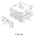
- an ink jet recording head comprising an orifice plate 40 having orifices 41 (ink ejection outlets), a top plate 400 having ink passage grooves 401 in communication with the respective orifices, and a heater board 100 having plural energy generating elements 101 for the liquid ejection and constituting a part of the ink passage.
- the orifice plate is used to constitute the ejection side surface with the same material for the purpose of preventing the deviation of the ejection of the ink droplet attributable to the difference in the wettability between the heater board and the top plate.
- the orifice is the important element influential to the ejection performance of the ink jet recording head. Particularly, the orifice through which the ink is ejected is the most important part. As described hereinbefore, together with the recent development in the image recording technique and the recent development in the recording head manufacturing technique, the size of the orifice (diameter of the orifice) is reduced, and plural orifices are arranged at a high density.
- the method (3) involves problems that the cost of the base material (Si) of the orifice plate is expensive, and that the manufacturing or the processing period is long.
- the method (4) involves the problems that the manufacturing period from the photolithography to the plating is long, and that auxiliary materials are required to be used, such as a substrate or photoresist.
- the method (5) is not enough to manufacture the satisfactory orifice.
- the CO2 gas laser and YAG laser do not have the laser output which is sufficient to manufacture, and therefore, the configuration and the accuracy of the produced orifice is not satisfactory.
- the orifice produced by the YAG laser is not circular, and in addition the material not completely removed by the laser is present around the orifice. Depending on the material and the thickness of the orifice plate, the sufficient opening is not produced.
- the orifices are formed one-by-one, and therefore, the time is requires for producing many orifices, so that the method is not suitable for the mass-production.
- the plural orifices are required to be formed at the respective correct positions.
- a moving mechanism for finely moving and finely positioning the laser is required, which increases the difficulties.
- the improvement has been investigated in the ink.
- the material of the recording head in contact with the ink therefore, is required to have sufficient resistivity against the ink.
- the orifice plate therefore, is required to have such a property. This may impose further difficulty in the production of the orifices.
- the ink jet recording head is comprised of an orifice plate, a top plate and a base plate. If the orifices are not in correct alignment with the corresponding ink passages with high precision, the ejection performance is influenced even to such an extent of the liability of ejection failure.
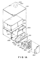
- Figures 1A and 1B are an exploded perspective view and a perspective view of an ink jet cartridge according to an embodiment of the present invention.
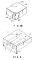
- Figure 2 is a perspective view of a top plate having ink passage grooves and ejection outlets.
- Figures 3A and 3B are schematic views of an apparatus for producing an ejection outlet using a laser beam.
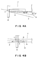
- Figures 4A and 4B show enlarged views of the laser beam for producing an ejection outlet.
- Figure 5 is a perspective view of a recording head comprising the heater board and a top plate joined therewith.
- Figure 6 shows the optical path of the laser for producing the ejection outlet.
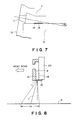
- Figure 7 is an enlarged view adjacent an ejection outlet.
- Figures 8 and 9 illustrate accuracy of the position of the liquid ejection.
- Figure 10 is a perspective view of an ink jet recording apparatus according to an embodiment of the present invention.
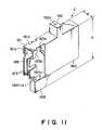
- Figure 11 is a perspective view of a cartridge according to an embodiment of the present invention.
- Figure 12 is a perspective view of an ink jet recording apparatus according to an embodiment of the present invention.
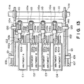
- Figure 13 is a top plan view of the ink jet recording apparatus of Figure 12.
- Figures 14 and 15 are side sectional views.
- Figure 16 is an exploded view of a conventional recording head.
- FIGS 1A and 1B show a recording head according to an embodiment of the present invention.
- the ink jet recording head has as a unit an ink container (ink supplying source) which is detachably mountable to an ink jet recording apparatus.
- the recording head comprises a heater board 100 including Si substrate, electrothermal transducers (ejection heaters) and aluminum or the like wiring for supplying electric power to the electrothermal transducers, wherein the electrothermal transducers and the wiring are formed by a film forming technique. It also comprises a wiring board 200 connected to the heater board 100. The corresponding lines are connected by wire bonding or the like.
- a top plate 400 has integral portions for constituting partition walls between adjacent ink passages, ejection outlets and a common liquid chamber or the like. It is made of resin material such as polyether sulfone.
- the supporting member 300 supports the wiring board 200 bonded thereto. It has a mounting reference relative to a carriage for scanningly moving the recording head.
- the supporting member 300 also functions as a heat radiating member for emitting heat from the heater board 100, the heat being produced by driving the recording head.
- An ink container 600 is supplied with ink from an ink storage (ink supplying source), and is effective to supply the ink to the common chamber constituted by the bonding between the heater board and the top plate 400.
- Designated by reference numerals 700 and 800 are a filter disposed in the supply container 606 adjacent an ink supply outlet to the common chamber, and a cover for the ink supply container 600.
- An absorbing material 900 for absorbing the ink is disposed in the main body 1000 of the cartridge.
- An ink supply port 2100 is used to supply the ink into the unit constituted by the above-described parts 100 - 800.
- the ink is supplied through the supply port 1200, by which the ink is filled in the absorbing material 900.
- the cartridge comprises a cover 1100, an air vent formed in the cover for the communication between the inside of the cartridge and the ambience, a liquid repelling material 1300 disposed at the inside of the air communicating vent 1400 which is effective to prevent leakage of the ink through the vent 1400.
- the unit constituted by the parts 100 - 300 is mounted to the portion 1010.
- the positioning or fixing can be accomplished by engagement between projections 1012 of the cartridge main assembly 1000 and holes formed in the supporting member 300, for example.
- the cartridge shown in Figure 1B is provided.
- the ink is supplied into the supply container 600 from the cartridge inside through the supply port 1200, a hole 320 formed in the supporting member 300 and an opening formed in a backside of the supply container 600 ( Figure 1A).
- the ink is further supplied into the common liquid chamber through a suitable supply pipe and an ink inlet 420 of the top plate 40.
- gaskets made of silicone rubber or butyl rubber or the like are used to seal the connections.
- FIG. 2 shows the structure of the top plate 7.
- the top plate 7 has a desired number of ink passage grooves 14 and ink ejection outlets (orifice) 11 formed in the orifice plate 10 which is integral with the top plate 7, although only two orifices are shown for the sake of simplicity.
- the top plate 7 is made of resin material exhibiting resistivity against the ink, such as polysulfone, polyethersulfone, polyphenylene oxide, polypropylene or the like.
- the top plate 7 is integrally molded in a mold with the orifice plate 10.
- the ink passage grooves 14 and the orifices 11 will be described.
- a resin material is molded using a mold having a reverse configuration of the grooves provided by machining or the like.
- the grooves 14 are formed in the top plate 7.
- the material is molded in a metal mold into a configuration without the orifices.
- an excimer laser beam is projected from an excimer laser apparatus to an ink passage side of the orifice plate 10 at a position where the orifice is to be formed.
- the resin material is evaporated and removed to provide an orifice 11.
- Figures 3A and 3B show the orifice formation in an orifice plate integral with the top plate by the application of the excimer laser beam.
- the laser beam is projected on the inside of the orifice plate 10, that is, to the groove side of the top plate
- Figure 3B shows the laser beam projected on the outer side of the orifice plate 10. Both for laser beam application to form an ejection outlet.
- a laser oscillator 1 oscillates KrF excimer laser beam, the laser beam 2 having a wavelength of 248 mm and a pulse width of approximately 14 micro-sec. in the form of pulses.
- the system comprises a synthetic quartz lens for converging the laser beam 2 a projection mask having a pattern of evaporated aluminum capable of blocking the laser beam 2.
- a plurality of holes having a diameter of 133 microns are arranged at a pitch of 212 microns to constitute a pattern of orifices.
- FIG 4A shows detail of orifice production.
- the excimer laser beam 2 is projected to the orifice plate 10 through the mask 4 to the ink passage side 14.
- the cross-sectional area of the orifice is tapered and converged toward the ejection direction.
- Designated by a reference 7 is a top plate having the integral ink passages 14.
- the configuration of the ejection outlet is conical with small diameter at the recording sheet side, and the axis of the conical configuration is inclined with respect to a normal line of the ejection plate.
- the ink jet head in this embodiment uses an integral top plate having an orifice plate and an ink passage plate, and the ejection outlets are tapered so as to have cross-sectional areas decreasing toward the ejection outlets by the application of the excimer laser beam to the ink passage side of the orifice plate. Therefore, the ejection speed is high, and the orifice surface is not easily wet, so that the ink ejection direction can be stabilized.
- the excimer laser beam is projected to the inside, a part of the laser beam is blocked by the ink passage wall 14A, as indicated by a reference 14B in Figure 6, and it is possible that the configuration of the ejection outlet is irregular.
- the configuration of the ejection outlet is very important influential to the volume, ejection direction and an ejection speed as well of the ejected ink.
- the excimer laser is projected with an inclination of 15 degrees with respect to the horizontal surface of the ink passage (the heater board surface during the head manufacturing step), as shown in Figure 4A.
- the central direction of the tapered ejection outlet ( Figure 7) is inclined by 15 ( ⁇ 2) degrees from the heater board surface.
- the angle of inclination is not limited to this, but can be properly selected by skilled in the art in accordance with the size of the passage or the like. It may be approximately 5 - 20 degrees.
- the cross-sectional configuration of the ejection outlet may be circular, trapezoidal or hexagonal or the like.
- the orifice cross-sectional configuration is as shown in Figure 4B. More particularly, the cross-sectional area of the ejection outlet 11 is enlarged in the ejection direction.
- reference numeral 8 designates a substrate (heater board) on which ejection energy generating elements are patterned; 9 designates an opening communicating with the ink passage; and 15 are electrothermal transducers functioning as ejection energy generating elements.
- the excimer laser is capable of oscillating ultraviolet laser beam and has advantages of high strength, narrow wavelength, good directivity, short pulse oscillation and capability of being converged by lens to increase the energy density.
- the excimer laser oscillator By the excimer laser oscillator, the mixture of rare gas and halogen is discharged and excited, by which a short pulse ultraviolet beam (15 - 35 ns). Kr-F, Xe-Cl and Ar-F lasers are widely used.
- the oscillation energy is 1000 mJ/pulse, and the frequency of the pulses is 30 - 1000 Hz.
- the short pulse ultraviolet beam of high strength such as the excimer laser beam
- the projected portion of the material is instantaneously dissolved and scattered with plasma and impact noise (ablative photodecomposition (APD)).
- APD abbreviated photodecomposition
- the manufacturing accuracy of the excimer laser is compared with that of the other lasers, for example, when the excimer laser, YAG laser and CO2 laser are projected on polyimide (PI) film, a sharp opening is formed by the KrF laser since the ultraviolet light is absorbed by the PI, but the YAG laser not in the ultraviolet region can form an opening, but the edge is not smooth, and in the case of CO2 laser (infrared) results in a crater around the opening.
- PI polyimide
- the excimer laser projection is not influential to metal such as SUS, non-transparent ceramic material or Si, and therefore, such materials are usable as a masking material when the excimer laser is used.
- Figure 5 is a perspective view of the main body of the recording head constituted by combining the heater board 8 and the top plate 7.
- the heater board 8 having the ejection heaters 15 or the like is abutted to the orifice plate 10, and is bonded thereto so as to constitute the main body of the recording head.
- the positioning or the bonding between the top plate and the orifice plate is not required, and therefore, the positional deviation or alignment error upon the bonding does not occur. Therefore, the number of rejects and the number of process steps are reduced, which are good from the standpoint of mass-production and the cost reduction of the recording head.
- the orifice or the ink passage is free from being clogged with the bonding agent.
- the heater board and the top plate 7 having the integral orifice plate 10 are put together, they are correctly positioned in the direction of the passage by abutting the heater board 8 to the end surface which is opposite from the ejection side surface of the orifice plate 10, and therefore, the overall positioning or the assembling steps are easier. In addition, there is no liability of removal of the orifice plate.
- the main body of the recording head may be in the form of a cartridge shown in Figure 1.
- an ink jet recording head including the recording head of this embodiment involves variation within a range in the amount of ejection, the direction of ejection and the ejection speed.
- the ejection direction is unstable due to fine foreign matter on the orifice surface, deterioration of the water repelling property or the like.
- the ejection direction varies in a conical variation space, as shown in Figure 8, about the laser beam incidence direction, that is, the central axis of the ejection outlet.
- Figure 9 shows the ink jet recording apparatus of this embodiment.
- a positioning surface of a metal plate 24 which is constructed to be parallel with the heater board and the passage groove of the ink jet head is supported on a head mounting surface 23A of a carriage inclined at the same angle ⁇ 2 as the inclination of the above-described laser beam by engagement between projections 23B of the carriage and recesses 24A of the recording head, by which the central direction of the liquid ejection is aligned with a normal direction of the recording material S ( Figure 9).
- the recording head is mounted on the head mounting surface 23A of the carriage 23 so that the central line L (incidence direction of the incidence direction of the laser beam) at the ejection outlet and the surface of the recording material S forms 90 degrees angle.
- the ink ejection direction is changed from the energy supplying direction to the ejection region, and the recording material is disposed so that the distance between the ejection region and the recording material is minimum, and the ink ejection direction is substantially perpendicular to the recording material.
- the energy supply direction to the ejection region is a pressure wave produced by a bubble formed by film boiling by the thermal energy produced from the electrothermal transducer element.
- the ejection outlet region is disposed at a vent portion of a member having plural ink guiding recess, and there are through openings produced by the application of high energy beam at the vent side.
- the accuracy in the position of shot of the ink on the recording material S is minimum in the head scanning direction, and the ink shot area 1 A has the minimum width. Therefore, if the comparison is made between the case in which the head is mounted so that the central line L of the ejection outlet is perpendicular to the recording material S ( Figure 9) and the case in which the heater board 8 and the metal plate 24 are aligned with the normal direction to the recording material S ( Figure 8), the shot area on the recording material S has a smaller width 1 A in the former case than in the width 1 B in the latter case.
- the shot accuracy is increased, and therefore, the deflection of the ink is made constant during the reciprocating movement of the carriage. Therefore, even if the recording operation is performed both during the forward and backward movement of the carriage, the sharp images can be obtained in any direction recordings.
- the angle control is effected at the main assembly of the recording apparatus, but it is possible that the metal plate which is a reference surface of the recording head or the positioning portion may be inclined properly.
- the present invention is applicable to an ink jet recording head which is not of a head exchanging type, but a type wherein only ink is replenished.
- Figure 10 shows an example of an ink jet recording apparatus in which the recording head is mounted on the carriage under the angular conditions shown in Figure 9.
- the ink jet printer of Figure 9 uses an exchangeable recording head cartridge.
- the cartridge 80 in Figure 10 may be the one shown in Figure 1.
- the cartridge 80 is detachably mounted on the carriage by a confining member 81.
- the carriage is reciprocally movable in the longitudinal direction along the shaft 21.
- the positioning of the cartridge 80 relative to the carriage can be established by holes formed in the cover 300 and projections of the carriage 23.
- the electric connection therebetween is established by contact between connecting pads on the wiring board and a connector on the carriage 23.
- the ink ejected from the recording head of the cartridge 80 is ejected to the recording material 13 which is confined on the platen 19 with a small clearance from the recording head so as to form an image on the recording material 18.
- ejection signals in accordance with the image data are supplied from a proper data source through a cable 16 and contacts connected thereto.
- reference numeral 17 designates a carriage motor for scanningly moving the carriage 23 along the shaft 21, 22 designates wire for transmitting the driving force from the motor 17 to the carriage 23.
- a feeding motor 20 is connected with the platen roller 19 to feed the recording material 18.
- the ink jet printer of this embodiment is capable of effect recording during the forward movement and during the backward movement, of the recording head.
- the cartridge C of this embodiment has an ink container and a recording head 186 at the upper and lower positions, respectively.
- the recording head 186 is produced in the similar manner as in the foregoing embodiment, using the excimer laser beam.
- the connector 185 of the recording head for receiving signals or the like for driving the recording head 186 and producing an output relating to a remaining amount of the ink is disposed at a position beside the ink container 180. Therefore, when the cartridge C is mounted to the carriage which will be described hereinafter, the height H can be reduced. By reducing the thickness W of the cartridge in the scanning direction, the size of the carriage can be reduced when the cartridge C is disposed beside it, as shown in Figure 2.
- a connector cover 183 is integrally formed with the outer wall of the container to prevent in advertent contact to the connector 185.
- a positioning portion 181 has abutment surfaces 181a and 181b in the two directions. By providing sufficient distances between such positioning surfaces and the positioning abutment surface of the recording head 186, the recording head can be assuredly positioned and fixed by the pressure with a pushing pin toward the slanted surface 184.
- a grip 182 is used when the cartridge C is mounted or dismounted relative to the mounting position.
- An air vent 182a is formed in the grip 182 to permit communication between the ambience and the inside of the ink container 180.
- a cut-away Portion 182a and a guide 183b function as guides when the cartridge C is mounted to the mounting portion.
- the recording head 186 in this embodiment has plural ejection outlets in the bottom surface of this Figure.
- ejection energy generating elements are produced to produce energy contributable to the ejection or discharge of the ink.
- the ejection energy generating elements are preferably in the form of thermal energy generating elements (electrothermal transducers) are preferable from the standpoint that the ejection outlets or the ejection outlets can be disposed at a high density.
- Figures 12 and 13 are a perspective view and a top plan view of the carriage of the ink jet recording apparatus for mounting the cartridge C shown in Figure 11 under the condition shown in Figure 9.
- four cartridges C1, C2, C3 and C4 are mounted on the carriage 102.
- the cartridges containing different color ink material, yellow ink, magenta ink, cyan ink and black ink, for example.
- four pushing pin 110 (A - D) are engaged and are urged to the left in Figure 13 by springs 110a (A - D).
- the connector holder 140 functioning as a supporting member is engaged with links 121 (link I and link II) through a shaft 120 (shaft I and shaft II) and is movable to the left and is movable to the left and right in accordance with rotation of an operating lever 107 engaging with the rink 121 (clockwise direction and counterclockwise direction).
- links 121 link I and link II
- shaft 120 shaft I and shaft II
- an operating lever 107 engaging with the rink 121 (clockwise direction and counterclockwise direction).
- the recording head 186 of the cartridge C is inserted from the upper to a front recess 102f1 of the mounting portion 102f.
- a rectangular portion 102h of the carriage 102 is engaged between guides 183b of the cartridge C, so that the cartridge C is roughly positioned.
- the operating lever 107 is rotated in the clockwise direction about the shaft 109, the holder 140 advances, so that the cut-away portion 183a of the cartridge C is advanced to the guide 154 of the carriage 102, and the pin 110 is engaged with the cartridge C, by which the cartridge C is mounted to the mounting portion 102f.
- the angular relation between the recording head and the recording sheet is as shown in Figure 9.
- a spring 159 is provided on the carriage 102 to produce urging force to improve the positioning accuracy of the cartridge C by backwardly pushing the cartridge C mounted on the mounting portion 102f.
- the free end 110b of the pushing rod 110 is contacted to the associated one of the four cartridges C at the abutment surface 101d to push the cartridge.
- An outer peripheral surface 110c of the pushing pin 110 is contacted to an abutment surface 102S of the carriage 102 to independently receive the thrust force perpendicular to the axis of the pushing pin. Therefore, the supporting member 140 receives only the reaction force by the spring 110a (springs A - D), and does not receive the thrust force. Therefore, when the plural cartridges are simultaneously released, the releasing operation can be carried out with small operating force to the releasing lever 107.
- the lever 107 is operated when an engaging shaft 106a integral with the main assembly connector 106 is engaged with an engaging hole 140b of the connector holder 140 by resilience force of the tension spring 141 ( Figure 14). Then, the main assembly connector 106 and the connector holder 140 move as a unit.
- the predetermined distance is the distance between the engaging shaft 106a and the engaging portion 140b, and a movement distance of the connector holder 140 permit (release) movement of the main assembly connector 103 from the positioned state.
- the main assembly connector 106 Since the main assembly connector 106 is combined with the head connector 85 with force stronger than that of the tension spring 141. The main assembly connector 106 is released from the connector holder 140. That is, the disengagement occurs. A large diameter portion of the engaging hole 140a is larger in the diameter than the engaging shaft 106a of the main assembly connector 106 and therefore, a gap appears therebetween. Accordingly, upon the engagement between the main assembly connector 106 and the head connector 185, the main assembly connector 106 is free from the connector holder 140, and therefore, the cartridge C is positioned relative to the carriage 102 only by the pressing force of the pressing pin 110, by which the correct positioning of the recording head 186 relative to the carriage 102 is assured.
- the lever 107 When the cartridge C is dismounted (released), the lever 107 is rotated in the counterclockwise direction from the upright position to the horizontal position ( Figure 12).
- the engaging shaft 106a is engaged with the heat connector 185 with strong force, but together with the rightward movement of the connector holder 140, the large diameter surface of the engaging hole 140a abuts the engaging shaft 106a, and release the main assembly connector 106 from the head connector 108 while pushing the engaging shaft 106a toward rear in Figure 12.
- the pushing pin 110 moves together with the connector holder 140 and is moved away from the recording head 186.
- a scanning rail 111 extends in the main scan direction of the carriage 102 and slidably supports the carriage.
- Designated by a reference numeral 111a is a bearing.
- a flexible cable 151 functions to transfer various signals with the cartridge C through the connector.
- a belt 152 functions to transmit the driving force for reciprocating the carriage 102. Pairs of rollers 117 and 118, 115 and 116 are effective to feed the recording material and are disposed before and after the recording position by the recording head 186.
- a platen 150 is effective to provide a flat recording surface of the recording material.
- Figure 14 shows the recording apparatus in the form of a printer, copying machine or facsimile machine, using the above-described structures.
- the main assembly 1000 of the recording apparatus is provided with a cover 1101 openable at the front side.
- the cover 1101 When the cover 1101 is opened, the inside of the main assembly becomes accessible.
- the opening of the cover permits the rotational movement of the lever 107 to permit mounting or dismounting of the cartridges C1, C2, C3 and C4 relative to the main assembly.
- the lever 107 indicated by the solid line is at the position for permitting mounting of the cartridge shown in Figure 11. At this position, the movement of the cover 1101 to the closed position is prevented.
- the cartridge shown by the broken lines is during the mounting operations.
- the cartridge shown by the solid lines is a recordable operating position in the main assembly of the apparatus.
- Reference numeral 1102 designates a flexible sheet for the electric wiring.
- a rail 112 cooperates with the rail 111 to support and guide the carriage 102.
- the connector holder 140 is shown as after the cartridge is fixed to the carriage by moving the lever 107 to its broken line position after the cartridge is mounted.
- Shafts 120 and 1202 are provided at both sides relative to the relative movement between the connector holder 140 and the carriage, and the positional levels are the same.
- the shafts are columnar for permitting movement in the two elongated holes having central long axis to the sides of the carriage.
- the shaft indicated by the solid lines correspond to the lever 107 indicated by the solid lines.
- the shafts 120 and 1202 further assure the parallel movement of the connector holder.
- the shafts 120 and 1202 are provided on other than the connector main body, and are disposed above and adjacent the pushing pin 110 for positioning the recording head, and therefore, the positioning accuracy of the pushing pins 110 is increased.
- Shafts similar to the shafts 120 and 1202 may be provided on the main assembly of the connector to stabilize the parallel movement of the connector main body, and after the connection of the connector it may be freed in the front-rear direction and in the lateral direction within the clearance from the side plate.
- the elongated slot of the shaft 1202 does not fix the shaft 1202 in the front-rear direction after the connector main body is connected, by which the positioning of the pin 110 acts only on the shaft 120.
- Figure 15 is a side view illustrating the engaging relation between the lever 107 and the shaft 120, and corresponds to a side view of the apparatus shown in Figure 13.
- the link 121 engages the lever 107 with the shaft 120.
- the main assembly is used as a copying machine. The structure will be briefly described. As shown in the Figure, there are an upper original cover, an optical reading means disposed below an original supporting platen glass, and means 1212 for converting the read information to electric signals. The electric signals are converted to recording head driving signals through the flexible sheet 1102 to produce a full-color ink image.
- a cassette 1210 is inserted into the bottom portion of the main assembly from a discharge tray 1213 side to supply the recording material in the direction opposite from the inserting direction.
- a feeding roller 1212 is provided in the recording material feeding station.
- the recording head is mounted on the carriage in the positional relation having been described in conjunction with Figure 9, and therefore, good recording is possible both during the forward movement and during the backward movement, of the recording head.
- the present invention is particularly suitably usable in an ink jet recording head and recording apparatus wherein thermal energy by an electrothermal transducer, laser beam or the like is used to cause a change of state of the ink to eject or discharge the ink. This is because the high density of the picture elements and the high resolution of the recording are possible.
- the typical structure and the operational principle are preferably the ones disclosed in U.S. Patent Nos. 4,723,129 and 4,740,796.
- the principle and structure are applicable to a so-called on-demand type recording system and a continuous type recording system.
- it is suitable for the on-demand type because the principle is such that at least one driving signal is applied to an electrothermal transducer disposed on a liquid (ink) retaining sheet or liquid passage, the driving signal being enough to provide such a quick temperature rise beyond a departure from nucleation boiling point, by which the thermal energy is provided by the electrothermal transducer to produce film boiling on the heating portion of the recording head, whereby a bubble can be formed in the liquid (ink) corresponding to each of the driving signals.
- the liquid (ink) is ejected through an ejection outlet to produce at least one droplet.
- the driving signal is preferably in the form of a pulse, because the development and contraction of the bubble can be effected instantaneously, and therefore, the liquid (ink) is ejected with quick response.
- the driving signal in the form of the pulse is preferably such as disclosed in U.S. Patents Nos. 4,463,359 and 4,345,262.
- the temperature increasing rate of the heating surface is preferably such as disclosed in U.S. Patent No. 4,313,124.
- the structure of the recording head may be as shown in U.S. Patent Nos. 4,558,333 and 4,459,600 wherein the heating portion is disposed at a bent portion, as well as the structure of the combination of the ejection outlet, liquid passage and the electrothermal transducer as disclosed in the above-mentioned patents.
- the present invention is applicable to the structure disclosed in Japanese Laid-Open Patent Application No. 123670/1984 wherein a common slit is used as the ejection outlet for plural electrothermal transducers, and to the structure disclosed in Japanese Laid-Open Patent Application No. 138461/1984 wherein an opening for absorbing pressure wave of the thermal energy is formed corresponding to the ejecting portion. This is because the present invention is effective to perform the recording operation with certainty and at high efficiency irrespective of the type of the recording head.
- the present invention is effectively applicable to a so-called full-line type recording head having a length corresponding to the maximum recording width.
- a recording head may comprise a single recording head and plural recording head combined to cover the maximum width.
- the present invention is applicable to a serial type recording head wherein the recording head is fixed on the main assembly, to a replaceable chip type recording head which is connected electrically with the main apparatus and can be supplied with the ink when it is mounted in the main assembly, or to a cartridge type recording head having an integral ink container.
- the provisions of the recovery means and/or the auxiliary means for the preliminary operation are preferable, because they can further stabilize the effects of the present invention.
- preliminary heating means which may be the electrothermal transducer, an additional heating element or a combination thereof.
- means for effecting preliminary ejection (not for the recording operation) can stabilize the recording operation.
- the recording head mountable may be a single corresponding to a single color ink, or may be plural corresponding to the plurality of ink materials having different recording color or density.
- the present invention is effectively applicable to an apparatus having at least one of a monochromatic mode mainly with black, a multi-color mode with different color ink materials and/or a full-color mode using the mixture of the colors, which may be an integrally formed recording unit or a combination of plural recording heads.
- the ink has been liquid. It may be, however, an ink material which is solidified below the room temperature but liquefied at the room temperature. Since the ink is controlled within the temperature not lower than 30 o C and not higher than 70 o C to stabilize the viscosity of the ink to provide the stabilized ejection in usual recording apparatus of this type, the ink may be such that it is liquid within the temperature range when the recording signal is the present invention is applicable to other types of ink. In one of them, the temperature rise due to the thermal energy is positively prevented by consuming it for the state change of the ink from the solid state to the liquid state. Another ink material is solidified when it is left, to prevent the evaporation of the ink.
- the ink is liquefied, and the liquefied ink may be ejected.
- Another ink material may start to be solidified at the time when it reaches the recording material.
- the present invention is also applicable to such an ink material as is liquefied by the application of the thermal energy.
- Such an ink material may be retained as a liquid or solid material in through holes or recesses formed in a porous sheet as disclosed in Japanese Laid-Open Patent Application No. 56847/1979 and Japanese Laid-Open Patent Application No. 71260/1985. The sheet is faced to the electrothermal transducers. The most effective one for the ink materials described above is the film boiling system.
- the ink jet recording apparatus may be used as an output terminal of an information processing apparatus such as computer or the like, as a copying apparatus combined with an image reader or the like, or as a facsimile machine having information sending and receiving functions.
- the top plate has an integral orifice plate, and the excimer laser beam is applied from the inside at such an angle that the wall constituting the groove is not influential to the excimer laser beam, by which an ink ejection or discharge outlet is formed.
- the recording head Upon the mounting of the ink jet head to the main assembly of the recording apparatus, the recording head is inclined at the same angle as the inclination of the laser beam. Therefore, a tapered ejection outlet can be stably provided, and the ejection direction is stabilized. In addition, during the recording operation, the accuracy of the position of the liquid shot is improved.
- An ink jet recording apparatus for recording on a recording material with ink includes an ink jet recording head mounting portion for mounting thereon an ink jet recording head having an ejection outlet converged in a direction of ink ejection and inclined relative to a base plate; a feeder for feeding the recording material; and a mounting device for mounting the ink jet recording head on the mounting portion so that the ink ejection outlet of the recording head is perpendicular to the recording material.
Landscapes
- Engineering & Computer Science (AREA)
- Manufacturing & Machinery (AREA)
- Physics & Mathematics (AREA)
- Optics & Photonics (AREA)
- Particle Formation And Scattering Control In Inkjet Printers (AREA)
- Ink Jet (AREA)
Applications Claiming Priority (2)
| Application Number | Priority Date | Filing Date | Title |
|---|---|---|---|
| JP22194/90 | 1990-02-02 | ||
| JP2219490 | 1990-02-02 |
Publications (3)
| Publication Number | Publication Date |
|---|---|
| EP0440263A2 true EP0440263A2 (de) | 1991-08-07 |
| EP0440263A3 EP0440263A3 (en) | 1991-12-04 |
| EP0440263B1 EP0440263B1 (de) | 1995-01-11 |
Family
ID=12075993
Family Applications (1)
| Application Number | Title | Priority Date | Filing Date |
|---|---|---|---|
| EP91101388A Expired - Lifetime EP0440263B1 (de) | 1990-02-02 | 1991-02-01 | Tintenstrahlaufzeichnungsgerät |
Country Status (6)
| Country | Link |
|---|---|
| US (1) | US5956054A (de) |
| EP (1) | EP0440263B1 (de) |
| JP (1) | JP3032021B2 (de) |
| CN (1) | CN1022392C (de) |
| DE (1) | DE69106535T2 (de) |
| ES (1) | ES2067057T3 (de) |
Cited By (5)
| Publication number | Priority date | Publication date | Assignee | Title |
|---|---|---|---|---|
| EP0500110A1 (de) * | 1991-02-21 | 1992-08-26 | Hewlett-Packard Company | Photoabtrageverfahren von wenigstens einer gestuften Öffnung, die ein polymeres Material durchdringt und eine Düsenplatte, die eine gestufte Öffnung aufweist |
| EP0564102A3 (de) * | 1992-04-02 | 1995-03-15 | Hewlett Packard Co | |
| EP0661158A3 (de) * | 1994-01-03 | 1997-01-15 | Xerox Corp | Tintenstrahldrucken. |
| EP1020288A3 (de) * | 1999-01-12 | 2000-08-16 | Hewlett-Packard GmbH | Tintenstrahldruckvorrichtung und Verfahren zur Steuerung der Tropfenform |
| EP1000744A3 (de) * | 1998-10-27 | 2001-01-31 | Canon Kabushiki Kaisha | Tintenstrahlaufzeichnungskopf, Tintenstrahlaufzeichnungskassette und Aufzeichnungsvorrichtung |
Families Citing this family (16)
| Publication number | Priority date | Publication date | Assignee | Title |
|---|---|---|---|---|
| US6960870B2 (en) * | 1997-07-29 | 2005-11-01 | Seiko Epson Corporation | Piezo-electric resonator and manufacturing method thereof |
| US6976295B2 (en) * | 1997-07-29 | 2005-12-20 | Seiko Epson Corporation | Method of manufacturing a piezoelectric device |
| JP4523133B2 (ja) * | 2000-08-31 | 2010-08-11 | セイコーインスツル株式会社 | 記録ユニット及びインクジェット式記録装置 |
| US6860588B1 (en) | 2000-10-11 | 2005-03-01 | Hewlett-Packard Development Company, L.P. | Inkjet nozzle structure to reduce drop placement error |
| US7147310B2 (en) * | 2002-01-30 | 2006-12-12 | Hewlett-Packard Development Company, L.P. | Printing-fluid container |
| US6648460B2 (en) | 2002-01-30 | 2003-11-18 | Hewlett-Packard Development Company, L.P. | High volumetric efficiency ink container vessel |
| US6962408B2 (en) | 2002-01-30 | 2005-11-08 | Hewlett-Packard Development Company, L.P. | Printing-fluid container |
| US7744202B2 (en) | 2002-01-30 | 2010-06-29 | Hewlett-Packard Development Company, L.P. | Printing-fluid container |
| US6877849B2 (en) * | 2003-01-23 | 2005-04-12 | Hewlett-Packard Development Company, L.P. | Printing system with high volumetric ink container vessel |
| US7104630B2 (en) * | 2003-07-31 | 2006-09-12 | Hewlett-Packard Development Company, L.P. | Printing-fluid container |
| US6959985B2 (en) * | 2003-07-31 | 2005-11-01 | Hewlett-Packard Development Company, L.P. | Printing-fluid container |
| US7004564B2 (en) * | 2003-07-31 | 2006-02-28 | Hewlett-Packard Development Company, L.P. | Printing-fluid container |
| KR20060123842A (ko) * | 2005-05-30 | 2006-12-05 | 삼성전자주식회사 | 잉크 토출장치와 이를 포함하는 화상형성장치 및 화상 형성방법 |
| US8783824B2 (en) * | 2007-09-27 | 2014-07-22 | Canon Kabushiki Kaisha | Capping unit for ink jet recording unit |
| US10507639B2 (en) * | 2015-04-17 | 2019-12-17 | 3Dbotics, Inc. | Modular printing apparatus for 3D printing |
| JP6797554B2 (ja) | 2016-05-06 | 2020-12-09 | キヤノン株式会社 | 通知装置および記録装置 |
Family Cites Families (21)
| Publication number | Priority date | Publication date | Assignee | Title |
|---|---|---|---|---|
| US4014029A (en) * | 1975-12-31 | 1977-03-22 | International Business Machines Corporation | Staggered nozzle array |
| CA1127227A (en) * | 1977-10-03 | 1982-07-06 | Ichiro Endo | Liquid jet recording process and apparatus therefor |
| JPS5936879B2 (ja) * | 1977-10-14 | 1984-09-06 | キヤノン株式会社 | 熱転写記録用媒体 |
| US4330787A (en) * | 1978-10-31 | 1982-05-18 | Canon Kabushiki Kaisha | Liquid jet recording device |
| FR2448979B1 (fr) * | 1979-02-16 | 1986-05-23 | Havas Machines | Dispositif destine a deposer sur un support des gouttes d'encre |
| US4345262A (en) * | 1979-02-19 | 1982-08-17 | Canon Kabushiki Kaisha | Ink jet recording method |
| US4463359A (en) * | 1979-04-02 | 1984-07-31 | Canon Kabushiki Kaisha | Droplet generating method and apparatus thereof |
| US4313124A (en) * | 1979-05-18 | 1982-01-26 | Canon Kabushiki Kaisha | Liquid jet recording process and liquid jet recording head |
| US4278983A (en) * | 1979-05-23 | 1981-07-14 | Gould Inc. | Ink jet writing device |
| US4450455A (en) * | 1981-06-18 | 1984-05-22 | Canon Kabushiki Kaisha | Ink jet head |
| US4558333A (en) * | 1981-07-09 | 1985-12-10 | Canon Kabushiki Kaisha | Liquid jet recording head |
| JPS58112746A (ja) * | 1981-12-28 | 1983-07-05 | Ricoh Co Ltd | オンデマンド型インクジエツトヘツド |
| JPS59123670A (ja) * | 1982-12-28 | 1984-07-17 | Canon Inc | インクジエツトヘツド |
| JPS59138461A (ja) * | 1983-01-28 | 1984-08-08 | Canon Inc | 液体噴射記録装置 |
| JPS6071260A (ja) * | 1983-09-28 | 1985-04-23 | Erumu:Kk | 記録装置 |
| JPS60219060A (ja) * | 1984-04-17 | 1985-11-01 | Canon Inc | 液体噴射記録装置 |
| IT1179109B (it) | 1984-09-10 | 1987-09-16 | Olivetti & Co Spa | Testina di stampa seriale a getto d'inchiostro |
| JPS61242852A (ja) * | 1985-04-19 | 1986-10-29 | Hitachi Koki Co Ltd | インクジエツトヘツドの製造方法 |
| GB8722085D0 (en) * | 1987-09-19 | 1987-10-28 | Cambridge Consultants | Ink jet nozzle manufacture |
| US5208604A (en) * | 1988-10-31 | 1993-05-04 | Canon Kabushiki Kaisha | Ink jet head and manufacturing method thereof, and ink jet apparatus with ink jet head |
| EP0367541B1 (de) * | 1988-10-31 | 1994-10-05 | Canon Kabushiki Kaisha | Verfahren zur Herstellung eines Tintenstrahldruckkopfes |
-
1991
- 1991-01-31 JP JP03010956A patent/JP3032021B2/ja not_active Expired - Fee Related
- 1991-02-01 EP EP91101388A patent/EP0440263B1/de not_active Expired - Lifetime
- 1991-02-01 DE DE69106535T patent/DE69106535T2/de not_active Expired - Fee Related
- 1991-02-01 ES ES91101388T patent/ES2067057T3/es not_active Expired - Lifetime
- 1991-02-02 CN CN91101249.4A patent/CN1022392C/zh not_active Expired - Fee Related
-
1997
- 1997-10-22 US US08/956,496 patent/US5956054A/en not_active Expired - Fee Related
Cited By (8)
| Publication number | Priority date | Publication date | Assignee | Title |
|---|---|---|---|---|
| US5469199A (en) * | 1990-08-16 | 1995-11-21 | Hewlett-Packard Company | Wide inkjet printhead |
| EP0500110A1 (de) * | 1991-02-21 | 1992-08-26 | Hewlett-Packard Company | Photoabtrageverfahren von wenigstens einer gestuften Öffnung, die ein polymeres Material durchdringt und eine Düsenplatte, die eine gestufte Öffnung aufweist |
| EP0564102A3 (de) * | 1992-04-02 | 1995-03-15 | Hewlett Packard Co | |
| EP0661158A3 (de) * | 1994-01-03 | 1997-01-15 | Xerox Corp | Tintenstrahldrucken. |
| EP1000744A3 (de) * | 1998-10-27 | 2001-01-31 | Canon Kabushiki Kaisha | Tintenstrahlaufzeichnungskopf, Tintenstrahlaufzeichnungskassette und Aufzeichnungsvorrichtung |
| US6416155B1 (en) | 1998-10-27 | 2002-07-09 | Canon Kabushiki Kaisha | Ink jet recording head, ink jet recording cartridge, and recording apparatus |
| EP1020288A3 (de) * | 1999-01-12 | 2000-08-16 | Hewlett-Packard GmbH | Tintenstrahldruckvorrichtung und Verfahren zur Steuerung der Tropfenform |
| US6299270B1 (en) | 1999-01-12 | 2001-10-09 | Hewlett-Packard Company | Ink jet printing apparatus and method for controlling drop shape |
Also Published As
| Publication number | Publication date |
|---|---|
| EP0440263B1 (de) | 1995-01-11 |
| CN1022392C (zh) | 1993-10-13 |
| US5956054A (en) | 1999-09-21 |
| JP3032021B2 (ja) | 2000-04-10 |
| JPH04211954A (ja) | 1992-08-03 |
| CN1054740A (zh) | 1991-09-25 |
| DE69106535T2 (de) | 1995-05-18 |
| ES2067057T3 (es) | 1995-03-16 |
| EP0440263A3 (en) | 1991-12-04 |
| DE69106535D1 (de) | 1995-02-23 |
Similar Documents
| Publication | Publication Date | Title |
|---|---|---|
| EP0440263B1 (de) | Tintenstrahlaufzeichnungsgerät | |
| EP0419181B1 (de) | Tintenstrahlaufzeichnungskopf, Kartusche und Apparat | |
| EP0739739B1 (de) | Verfahren zum Herstellen eines Tintenstrahlaufzeichnungskopfes | |
| EP0419190B1 (de) | Tintenstrahldruckkopf, -Kassette und -Gerät | |
| JP4846028B2 (ja) | インクジェット記録ヘッド | |
| EP0709199B1 (de) | Tintenstrahlkopf, Tintenstrahlkopfkassette, Tintenstrahlapparat und Verfahren zur Herstellung eines solchen Tintenstrahlkopfes | |
| EP0636480B1 (de) | Tintenstrahlaufzeichnungskopf, Aufzeichnungsgerät und Herstellungsverfahren und Vorrichtung für die Herstellung des Kopfes | |
| US6168254B1 (en) | Ink jet recording apparatus | |
| US5694684A (en) | Manufacturing method for ink jet recording head | |
| US20020075357A1 (en) | Liquid ejection head and method of manufacturing the liquid ejection head | |
| JPH10258386A (ja) | レーザ加工方法および該レーザ加工方法を用いた液体噴射記録ヘッドの製造方法 | |
| US20010050703A1 (en) | Liquid eject head, cartridge and image forming apparatus, and manufacturing method of liquid eject head | |
| JPH11147314A (ja) | インクジェット記録ヘッド及びインクジェット記録装置 | |
| JP2708593B2 (ja) | インクジェット記録ヘッド及び該記録ヘッドの製造方法 | |
| US6877225B1 (en) | Method of manufacturing an ink jet head | |
| EP0786305B1 (de) | Laserbearbeitungsvorrichtung und Verfahren zur Herstellung eines Flüssigkeitsstrahlaufzeichnungskopfes mittels einer solchen Laserbearbeitungsvorrichtung | |
| JP2764418B2 (ja) | インクジェット記録ヘッドの製造方法および該方法によって製造されたインクジェット記録ヘッド | |
| JP3198219B2 (ja) | インクジェット記録ヘッドおよびインクジェット記録装置 | |
| JPH10175299A (ja) | インクジェット記録装置 | |
| JPH10181004A (ja) | 液体噴射記録ヘッドおよびその製造方法 | |
| JPH06155745A (ja) | インクジェット記録ヘッドおよびその製造方法およびインクジェット記録装置 | |
| JP2001253067A (ja) | 記録ヘッドとキャリッジ及びインクジェット記録装置 | |
| JP2000198203A (ja) | インクジェット記録ヘッド、インクジェット記録カ―トリッジおよび記録装置 | |
| JPH03184862A (ja) | インクジェット記録ヘッド |
Legal Events
| Date | Code | Title | Description |
|---|---|---|---|
| PUAI | Public reference made under article 153(3) epc to a published international application that has entered the european phase |
Free format text: ORIGINAL CODE: 0009012 |
|
| 17P | Request for examination filed |
Effective date: 19910201 |
|
| AK | Designated contracting states |
Kind code of ref document: A2 Designated state(s): BE DE ES FR GB IT NL |
|
| PUAL | Search report despatched |
Free format text: ORIGINAL CODE: 0009013 |
|
| AK | Designated contracting states |
Kind code of ref document: A3 Designated state(s): BE DE ES FR GB IT NL |
|
| 17Q | First examination report despatched |
Effective date: 19930525 |
|
| GRAA | (expected) grant |
Free format text: ORIGINAL CODE: 0009210 |
|
| AK | Designated contracting states |
Kind code of ref document: B1 Designated state(s): BE DE ES FR GB IT NL |
|
| REF | Corresponds to: |
Ref document number: 69106535 Country of ref document: DE Date of ref document: 19950223 |
|
| ET | Fr: translation filed | ||
| REG | Reference to a national code |
Ref country code: ES Ref legal event code: FG2A Ref document number: 2067057 Country of ref document: ES Kind code of ref document: T3 |
|
| ITF | It: translation for a ep patent filed | ||
| PLBE | No opposition filed within time limit |
Free format text: ORIGINAL CODE: 0009261 |
|
| STAA | Information on the status of an ep patent application or granted ep patent |
Free format text: STATUS: NO OPPOSITION FILED WITHIN TIME LIMIT |
|
| 26N | No opposition filed | ||
| ITTA | It: last paid annual fee | ||
| REG | Reference to a national code |
Ref country code: GB Ref legal event code: IF02 |
|
| PGFP | Annual fee paid to national office [announced via postgrant information from national office to epo] |
Ref country code: ES Payment date: 20071228 Year of fee payment: 18 |
|
| PGFP | Annual fee paid to national office [announced via postgrant information from national office to epo] |
Ref country code: IT Payment date: 20080222 Year of fee payment: 18 Ref country code: GB Payment date: 20080226 Year of fee payment: 18 Ref country code: DE Payment date: 20080229 Year of fee payment: 18 Ref country code: NL Payment date: 20080220 Year of fee payment: 18 |
|
| PGFP | Annual fee paid to national office [announced via postgrant information from national office to epo] |
Ref country code: FR Payment date: 20080221 Year of fee payment: 18 |
|
| PGFP | Annual fee paid to national office [announced via postgrant information from national office to epo] |
Ref country code: BE Payment date: 20080122 Year of fee payment: 18 |
|
| BERE | Be: lapsed |
Owner name: *CANON K.K. Effective date: 20090228 |
|
| GBPC | Gb: european patent ceased through non-payment of renewal fee |
Effective date: 20090201 |
|
| NLV4 | Nl: lapsed or anulled due to non-payment of the annual fee |
Effective date: 20090901 |
|
| REG | Reference to a national code |
Ref country code: FR Ref legal event code: ST Effective date: 20091030 |
|
| PG25 | Lapsed in a contracting state [announced via postgrant information from national office to epo] |
Ref country code: NL Free format text: LAPSE BECAUSE OF NON-PAYMENT OF DUE FEES Effective date: 20090901 |
|
| PG25 | Lapsed in a contracting state [announced via postgrant information from national office to epo] |
Ref country code: DE Free format text: LAPSE BECAUSE OF NON-PAYMENT OF DUE FEES Effective date: 20090901 |
|
| PG25 | Lapsed in a contracting state [announced via postgrant information from national office to epo] |
Ref country code: BE Free format text: LAPSE BECAUSE OF NON-PAYMENT OF DUE FEES Effective date: 20090228 |
|
| REG | Reference to a national code |
Ref country code: ES Ref legal event code: FD2A Effective date: 20090202 |
|
| PG25 | Lapsed in a contracting state [announced via postgrant information from national office to epo] |
Ref country code: GB Free format text: LAPSE BECAUSE OF NON-PAYMENT OF DUE FEES Effective date: 20090201 Ref country code: FR Free format text: LAPSE BECAUSE OF NON-PAYMENT OF DUE FEES Effective date: 20090302 |
|
| PG25 | Lapsed in a contracting state [announced via postgrant information from national office to epo] |
Ref country code: ES Free format text: LAPSE BECAUSE OF NON-PAYMENT OF DUE FEES Effective date: 20090202 |
|
| PG25 | Lapsed in a contracting state [announced via postgrant information from national office to epo] |
Ref country code: IT Free format text: LAPSE BECAUSE OF NON-PAYMENT OF DUE FEES Effective date: 20090201 |