EP0440070B1 - Energiesparschaltung in einem hydraulischen Gerät - Google Patents
Energiesparschaltung in einem hydraulischen Gerät Download PDFInfo
- Publication number
- EP0440070B1 EP0440070B1 EP91100748A EP91100748A EP0440070B1 EP 0440070 B1 EP0440070 B1 EP 0440070B1 EP 91100748 A EP91100748 A EP 91100748A EP 91100748 A EP91100748 A EP 91100748A EP 0440070 B1 EP0440070 B1 EP 0440070B1
- Authority
- EP
- European Patent Office
- Prior art keywords
- fluid line
- pilot
- direction control
- pass
- autodeceleration
- Prior art date
- Legal status (The legal status is an assumption and is not a legal conclusion. Google has not performed a legal analysis and makes no representation as to the accuracy of the status listed.)
- Expired - Lifetime
Links
- 239000012530 fluid Substances 0.000 claims description 183
- 238000006073 displacement reaction Methods 0.000 claims description 27
- 238000011144 upstream manufacturing Methods 0.000 claims description 18
- 230000007935 neutral effect Effects 0.000 claims description 15
- 230000001172 regenerating effect Effects 0.000 claims description 13
- 238000010586 diagram Methods 0.000 description 2
- 238000010276 construction Methods 0.000 description 1
- 230000007423 decrease Effects 0.000 description 1
- 230000003247 decreasing effect Effects 0.000 description 1
- 230000000694 effects Effects 0.000 description 1
- 238000005516 engineering process Methods 0.000 description 1
- 238000005381 potential energy Methods 0.000 description 1
Images
Classifications
-
- E—FIXED CONSTRUCTIONS
- E02—HYDRAULIC ENGINEERING; FOUNDATIONS; SOIL SHIFTING
- E02F—DREDGING; SOIL-SHIFTING
- E02F9/00—Component parts of dredgers or soil-shifting machines, not restricted to one of the kinds covered by groups E02F3/00 - E02F7/00
- E02F9/20—Drives; Control devices
- E02F9/22—Hydraulic or pneumatic drives
- E02F9/2217—Hydraulic or pneumatic drives with energy recovery arrangements, e.g. using accumulators, flywheels
-
- E—FIXED CONSTRUCTIONS
- E02—HYDRAULIC ENGINEERING; FOUNDATIONS; SOIL SHIFTING
- E02F—DREDGING; SOIL-SHIFTING
- E02F9/00—Component parts of dredgers or soil-shifting machines, not restricted to one of the kinds covered by groups E02F3/00 - E02F7/00
- E02F9/20—Drives; Control devices
- E02F9/22—Hydraulic or pneumatic drives
- E02F9/2278—Hydraulic circuits
- E02F9/2296—Systems with a variable displacement pump
Definitions
- This invention relates to an energy regenerative circuit adapted to a hydraulic apparatus of an operation machine such as an excavator, a crane truck or the like.
- a variable displacement pump controlled by a capacity control mechanism is connected to a fluid tank via a by-pass fluid line, and a pilot pump is connected to said fluid tank; an actuator is controlled by a direction control valve; said by-pass fluid line and said capacity control mechanism are connected together via a by-pass pressure signal fluid line; and a first pilot valve is provided to open and close said by-pass pressure signal fluid line.
- a circuit is known from EP-A- 309 987.
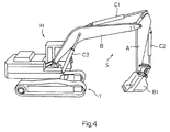
- a (front) operation device S consisting of a boom B, an arm A, a bucket B1, hydraulic cylinders C1 and C2, and the like is provided on the main vehicle body H which can perform a turning motion.
- the boom B is supported on the main vehicle body H such that it is operated by a boom cylinder C3 which is an actuator.
- the weight W of the operation device S is exerted on a chamber of the loaded side which is the lower chamber of the boom cylinder C3 which is partitioned by a piston.
- symbol T denotes a travelling device of the excavator.
- the above publication discloses a hydraulic circuit of a construction machinery in which a hydraulic line of an actuator on which the load is exerted is coupled to a discharge line of a variable displacement pump whose capacity is controlled by a control mechanism via a change-over valve which is changed over by said control mechanism, wherein said hydraulic line coupled to the loaded-side chamber of said actuator is provided with an energy regenerative valve which is changed over by said control mechanism when the pressurized fluid in the loaded-side chamber is drained in order to shunt the pressurized fluid drained from the loaded-side chamber and to add it to said hydraulic line of the unloaded-side chamber of said actuator, and a pressure reduction signal valve for reducing the discharge capacity of the pump is provided between said variable displacement pump and said control mechanism.
- the object of this invention is to provide an energy regenerative circuit of an improved hydraulic apparatus which makes it possible to regenerate the holding pressure in the loaded-side chamber of the actuator maintaining high efficiency while saving the energy, and to obtain the compacting function of the operation device more quickly and stably.
- this invention provides an energy regenerative circuit of a hydraulic apparatus according to claim 1.
- Claim 2 is directed to an advantageous embodiment of the invention.
- a variable displacement pump controlled by a capacity control mechanism is connected to a fluid tank via a by-pass fluid line and a pilot pump is connected to said fluid tank via an autodeceleration signal fluid line; the upstream side of orifice of said by-pass fluid line and the downstream side of orifice of said autodeceleration signal fluid line are controlled to be opened or closed when a direction control valve that controls an actuator is at its neutral position or at its operation positions; the upstream side of said signal orifice of said by-pass fluid line and said capacity control mechanism are connected together via a by-pass pressure signal fluid line, and said pilot pump and said capacity control mechanism are connected together via a pilot pressure transfer fluid line; a first pilot valve is provided to open and close said by-pass pressure signal fluid line and said pilot pressure transfer fluid line; said first pilot valve is connected at its pilot port side to the upstream side of said direction control valve of said autodeceleration signal fluid line via an autodeceleration pressure signal fluid line that is opened and closed by the second pilot valve; said first pilot pilot valve
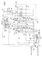
- Fig. 1 illustrates a portion of the energy regenerative circuit in the hydraulic apparatus adapted, for example, to the excavator shown in Fig. 4.
- a variable displacement pump 204 whose discharge rate is controlled by a capacity control mechanism 202, and a pilot pump 206. These pumps are driven by an engine E.
- the variable displacement pump 204 is connected to a fluid tank 212 via a by-pass fluid line 210 that has a signal orifice 208.
- the pilot pump 206 is connected to the fluid tank 212 via an autodeceleration signal fluid line 216 formed on the downstream side of the orifice 214.
- a direction control valve 218 is provided on the upstream side of the signal orifice 208 of by-pass fluid line 210 and on the downstream side of the orifice 214 of autodeceleration signal fluid line 216 to open and close them simultaneously.
- the direction control valve 218 opens the above two fluid lines when it is at its neutral position, and closes them when it is in operation.
- the direction control valve 218 controls an actuator 220 which, in this case, consists of a boom cylinder C3 that has a loaded-side chamber 222 on the side of piston head and an unloaded-side chamber 224 on the side of piston rod.
- the piston rod supports the load W of the operation device S such as boom B and the like.
- the load W acts on the loaded-side chamber 222 as load-holding pressure (when the operation device S is above the ground).
- the position of the direction control valve 218 is changed over by the secondary pilot pressure of a pressure-reducing valve that is not shown but that is connected to a loaded-side chamber pilot fluid line 226 and an unloaded-side chamber pilot fluid line 228.
- the side for controlling the by-pass fluid line 210 of the direction control valve 218 consists of a 6-port 3-position change-over valve that can be changed over to a neutral position designated at #1 in Fig. 1, to an actuator loaded-side chamber acting position designated at #2 and to an actuator unloaded-side chamber acting position designated at #3.
- the side for controlling the autodeceleration signal fluid line 216 consists of a 2-port 3-position change-over valve that can be changed over to a neutral position designated at #4 in Fig. 1, to an actuator loaded-side chamber acting position designated at #5 and to an actuator unloaded-side chamber acting position designated at #6.
- Another direction control valve 232 is provided on the upstream side of the direction control valve 218 of the by-pass fluid line 210 and on the upstream side of an autodeceleration pressure signal fluid line 230 that will be described later of the autodeceleration signal fluid line 216, in order to close both of these fluid lines when it is at its neutral position and to close them when it is at its operation position.
- the position of said other direction control valve 232 for controlling another actuator is changed over based on the secondary pilot pressure of another pressure-reducing valve.
- the side for controlling the by-pass fluid line 210 of the another direction control valve 232 consists of a 6-port 3-position change-over valve that can be changed over to a neutral position #7, and to operation positions #8 and #9.
- the side for controlling the autodeceleration signal fluid line 216 consists of a 2-port 3-position change-over valve that can be changed over to a neutral position #10, and to operation positions #11 and #12.
- the pressure-reducing valves for controlling the direction control valves 218 and 232 are controlled by an operation lever provided in the cab.
- variable displacement pump 204 When the direction control valves 218 and 232 are operated, the variable displacement pump 204 is connected to the direction control valves 218 and 232 through main fluid line 211, such that the discharge pressure of the variable displacement pump 204 can be fed to the actuators thereof.
- a pressure switch 236 is connected to the autodeceleration signal fluid line 216 via signal fluid line 234.
- the pressure switch 236 is turned on when the autodeceleration signal fluid path 216 is closed by the direction control valves 218 and 232, and is turned off when the autodeceleration signal fluid line 216 is opened.
- the pressure switch 236 is turned on, the operation magnet M of governor lever G of the engine E is excited, and the governor lever G is moved to the position of a rated speed.
- the pressure switch 236 is turned off, the magnet M is de-energized, and the governor lever G is moved to the position of a low speed.
- the upstream side of signal orifice 208 of the by-pass fluid line 210 and the capacity control mechanism 202 are connected together through by-pass pressure signal fluid line 238. Further, the pilot pump 206 and the capacity control mechanism 202 are connected together through pilot pressure transfer fluid line 239.
- the capacity control mechanism 202 consists of a capacity control cylinder which is controlled to move toward the direction of a small flow rate indicated by arrow B when the hydraulic pressure that is fed is great and to move toward the direction of a large flow rate indicated by arrow A when the hydraulic pressure is small.
- the by-pass pressure signal fluid line 238 and pilot pressure transfer fluid line 239 are opened and closed by the first pilot valve 240.
- the pilot port side of the first pilot valve 240 is connected to the upstream side of the direction control valve 218 of the autodeceleration signal fluid line 216 via autodeceleration pressure signal fluid line 230 which is opened and closed by the second pilot valve 242.
- the pilot port side of the second pilot valve 242 is connected to the loaded-side chamber pilot fluid line 226 of the direction control valve 218 via pilot pressure signal fluid line 244.
- the second pilot valve 242 closes the autodeceleration pressure signal fluid line 230 (position designated at #14 in Fig. 4) and opens this fluid line (position designated at #13 in Fig. 4) when no pilot pressure acts thereon.
- the second pilot valve 242 consists of a 3-port 2-position change-over valve and has an internal fluid line that is so constituted that when a position #13 is assumed to open the autodeceleration pressure signal fluid line 230, this fluid line 230 is connected to the pilot port side of the first pilot valve 240 via a fluid line 246 and is further connected to the fluid tank 212 via another branch fluid line 250 that has an orifice 248.
- the first pilot valve 240 consists of a 4-port 2-position change-over valve which opens the by-pass pressure signal fluid line 238 at a position designated at #16 and further closes the pilot pressure transfer fluid line 239. At the position #15, furthermore, the first pilot valve 240 closes the by-pass pressure signal fluid line 238 and opens the pilot pressure transfer fluid line 239.
- the first pilot valve 240 has an internal fluid line that is so constituted that at the position where the pilot pressure transfer fluid line 239 is opened, the pilot pressure transfer fluid line 239 is connected to the fluid tank 212 via a fluid line 256 that has two orifices 252 and 254, and is further connected to the capacity control mechanism 202 via by-pass pressure signal fluid line 238 and fluid line 258 that is branched from between the two orifices 252 and 254 of the fluid line 256.
- the direction control valve 218 assumes the positions designated at #1 and #4 in Fig. 1 in the by-pass fluid line 210 and autodeceleration signal fluid line 216.
- the another direction control valve 232 is presumed to remain at the neutral position.
- the by-pass fluid line 210 and the autodeceleration signal fluid line 216 are both opened.
- the pressure switch 236 is turned off and the governor lever G is at the low-speed position.
- the second pilot valve 242 opens the autodeceleration pressure signal fluid line 230 at the position #13 of Fig. 1. However, since the autodeceleration pressure is low, the first pilot valve 240 assumes the position #16 to close the pilot pressure transfer fluid line 239 and to open the by-pass pressure signal fluid line 238. Discharge pressure of the variable displacement pump 204 is fed to the capacity control mechanism 202 via by-pass pressure signal fluid line 238.
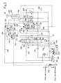
- the secondary pilot pressure acts on the direction control valve 218 from the pressure-reducing valve that is not shown via unloaded-side chamber pilot fluid line 228; i.e., the direction control valve 218 is changed over to the positions designated at #3 and #6 in the by-pass fluid line 210 and autodeceleration signal fluid line 216 as shown in Fig. 2.
- the by-pass fluid line 210 and autodeceleration signal fluid line 216 are both closed.
- the pressure switch 236 is turned on, and the governor lever G is shifted to the position of the rated speed.
- the second pilot valve 242 at the position #13 of Fig. 2 opens the autodeceleration pressure signal fluid line 230 but the autodeceleration signal fluid line 216 remains closed. Due to the function of the orifice 248 of branch fluid line 250, furthermore, the autodeceleration pressure rises and the first pilot valve 240 is switched to the position #15.
- the by-pass pressure signal fluid line 238 is closed and the pilot pressure transfer fluid line 239 is opened.
- variable displacement pump 204 is controlled to a medium dicharge rate.
- the pressurized fluid discharged from the thus controlled variable displacement pump 204 is fed to the unloaded-side chamber 224 of the actuator 220 via main fluid line 211, internal fluid line 262 having orifice 260 in the direction control valve 218, and fluid line 264.
- the load-holding fluid in the loaded-side chamber 222 whose pressure is elevated by the action of load W of the operation device S is fed to another internal fluid line 268 in the direction control valve 218 via fluid line 266.
- the load-holding pressurized fluid is returned to the fluid tank 212 via the orifice 270 provided for the internal fluid line 268 and return fluid line 246.
- the load-holding pressurized fluid is further partly fed to the unloaded-side chamber 224 of the actuator 220 via check valve 274 of a further internal fluid line 272 and fluid line 264.
- the boom B i.e. the operation device S, is allowed to descend.
- the pressurized fluid may often be fed to the unloaded-side chamber 224 of the actuator 220 in order to compact the ground by the operation device.
- the unloaded-side chamber 224 When the boom is lowered and grounded, the unloaded-side chamber 224 is converted into the loaded side.
- the hydraulic pressure in the loaded-side chamber 222 is so lowered as to become equal to the line pressure of the fluid tank 212, and no pressurized fluid is fed to the unloaded-side chamber 224.
- the variable displacement pump 204 is maintained under a medium discharge rate condition. However, since the by-pass fluid line 210 is closed, the pressurized fluid is fed to the unloaded-side chamber 224 stably and continuously.
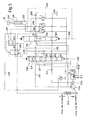
- the secondary pilot pressure acts on the direction control valve 218 from the pressure-reducing valve that is not shown via loaded-side chamber pilot fluid line 226; i.e., the direction control valve 218 is changed over to the positions #2 and #5 in the by-pass fluid line 210 and autodeceleration signal fluid line 216.
- the by-pass fluid line 210 and the autodeceleration signal fluid line 216 are both closed.
- the pressure switch 236 is turned, and the governor lever G is shifted to the position of the rated speed.
- the second pilot valve 242 receives the secondary pilot pressure via pilot pressure signal fluid line 244, and is changed over to a position #14 of Fig. 3 to close the autodeceleration pressure signal fluid line 230.
- the first pilot valve 240 is changed over to a position #16, whereby the by-pass pressure signal fluid line 238 is opened and the pilot pressure transfer fluid line 239 is closed.
- the by-pass pressure signal fluid line 238 is opened, the by-pass fluid line 210 is closed by the direction control valve 218 and the hydraulic pressure in the by-pass pressure signal fluid line 238 becomes equal to the tank pressure.
- the variable displacement pump 204 is controlled to exhibit its maximum discharge rate.
- the pressurized fluid discharged from the variable displacement pump 204 is fed to the loaded-side chamber 222 of the actuator 220 via main fluid line 211, internal fluid line 276 of the direction control valve 218 and fluid line 266.
- the pressurized fluid of the autodeceleration pressure signal fluid line 230 escapes into the fluid tank 212 via branch fluid line 250 that has the orifice 248 of second pilot valve 242. Therefore, the first pilot valve 240 is changed over to the position #16 of Fig. 1.
- the hydraulic pressure in the by-pass pressure signal fluid line 238 becomes equal to the tank pressure, and the variable displacement pump 204 is controlled to exhibit the greatest discharge rate.
Landscapes
- Engineering & Computer Science (AREA)
- Mining & Mineral Resources (AREA)
- Civil Engineering (AREA)
- General Engineering & Computer Science (AREA)
- Structural Engineering (AREA)
- Fluid-Pressure Circuits (AREA)
- Operation Control Of Excavators (AREA)
Claims (2)
- Energiesparschaltung für ein hydraulisches Gerät, bei der
eine durch eine Leistungssteuereinrichtung (202) gesteuerte verstellbare Pumpe (204) mit einem Fluidtank (212) über eine Ausweich-Fluidleitung (210) verbunden ist und eine Servopumpe an den Fluidtank (212) angeschlossen ist;
ein Stellorgan (220) durch ein Wegeventil (218) gesteuert wird;
die Ausweich-Fluidleitung (210) und die Leistungssteuereinrichtung miteinander durch eine Drucksignalausweichfluidleitung (238) verbunden sind; und
ein erstes Servoventil (240) vorgesehen ist, um die Drucksignalausweichfluidleitung (238) zu öffnen und zu schließen,
dadurch gekennzeichnet, daß
eine Selbstverzögerungssignalfluidleitung (216), die die Servopumpe (206) mit dem Fluidtank (212) verbindet, und die Ausweichfluidleitung (210) so gesteuert werden, daß sie geöffnet oder geschlossen werden, wenn das Wegeventil (218) in seiner neutralen Stellung bzw. seiner Arbeitsstellung ist;
die Servopumpe (206) und der Leistungssteuermechanismus (202) miteinander über eine Servodruckübertragungsfluidleitung (239) verbunden sind, die durch das erste Servoventil (240) geöffnet und geschlossen wird;
eine Öffnung (208) in der Ausweichfluidleitung (210) stromabwärts vom Wegeventil (218) und der Verbindung zwischen der Ausweichfluidleitung und der Servodruckübertragungsfluidleitung (239) vorgesehen ist;
eine Öffnung (214) in der Selbstverzögerungssignalfluidleitung stromaufwärts vom Wegeventil vorgesehen ist; und
das erste Servoventil (240) an seinem Steueranschluß mit der Selbstverzögerungsfluidleitung (216) stromaufwärts vom Wegeventil (218) über eine Selbstverzögerungsdrucksignalfluidleitung (230) verbunden ist. - Energiesparschaltung für ein hydraulisches Gerät nach Anspruch 2, bei der ein weiteres Wegeventil (232) vorgesehen ist, das, wenn es in seiner neutralen Stellung oder seinen Arbeitsstellungen ist, die Ausweichfluidleitung (210) stromaufwärts vom Wegeventil (218) und die Selbstverzögerungssignalfluidleitung (216) stromaufwärts von der Selbstverzögerungsdrucksignalfluidleitung (230) öffnet oder schließt.
Applications Claiming Priority (4)
| Application Number | Priority Date | Filing Date | Title |
|---|---|---|---|
| JP394190U JPH0396404U (de) | 1990-01-22 | 1990-01-22 | |
| JP3941/90U | 1990-01-22 | ||
| JP7617/90U | 1990-01-31 | ||
| JP761790U JPH0754642Y2 (ja) | 1990-01-31 | 1990-01-31 | 油圧装置のエネルギー再生回路 |
Publications (3)
| Publication Number | Publication Date |
|---|---|
| EP0440070A2 EP0440070A2 (de) | 1991-08-07 |
| EP0440070A3 EP0440070A3 (en) | 1992-07-08 |
| EP0440070B1 true EP0440070B1 (de) | 1995-05-24 |
Family
ID=26337616
Family Applications (1)
| Application Number | Title | Priority Date | Filing Date |
|---|---|---|---|
| EP91100748A Expired - Lifetime EP0440070B1 (de) | 1990-01-22 | 1991-01-22 | Energiesparschaltung in einem hydraulischen Gerät |
Country Status (4)
| Country | Link |
|---|---|
| US (1) | US5046309A (de) |
| EP (1) | EP0440070B1 (de) |
| CA (1) | CA2034613C (de) |
| DE (1) | DE69109877T2 (de) |
Families Citing this family (37)
| Publication number | Priority date | Publication date | Assignee | Title |
|---|---|---|---|---|
| US5207059A (en) * | 1992-01-15 | 1993-05-04 | Caterpillar Inc. | Hydraulic control system having poppet and spool type valves |
| US5237819A (en) * | 1992-02-21 | 1993-08-24 | Caterpillar Inc. | Pilot control circuit with preselected actuation delays |
| EP0564939B1 (de) * | 1992-04-04 | 1995-12-13 | Mannesmann Rexroth AG | Hydraulische Steuereinrichtung für mehrere Verbraucher |
| US5220862A (en) * | 1992-05-15 | 1993-06-22 | Caterpillar Inc. | Fluid regeneration circuit |
| US5433076A (en) * | 1992-10-29 | 1995-07-18 | Hitachi Construction Machinery Co., Ltd. | Hydraulic control valve apparatus and hydraulic drive system |
| DE69302012T2 (de) * | 1992-12-04 | 1996-09-05 | Hitachi Construction Machinery Co., Ltd., Tokio/Tokyo | Hydraulischer regenerator |
| US5349151A (en) * | 1993-02-08 | 1994-09-20 | Savair Inc. | Low impact flow control device |
| JP3434514B2 (ja) * | 1993-03-23 | 2003-08-11 | 日立建機株式会社 | 油圧作業機の油圧駆動装置 |
| US5575148A (en) * | 1993-11-30 | 1996-11-19 | Hitachi Construction Machinery Co., Ltd. | Hydraulic pump control system |
| US5570286A (en) * | 1993-12-23 | 1996-10-29 | Lord Corporation | Regenerative system including an energy transformer which requires no external power source to drive same |
| JP3550260B2 (ja) * | 1996-09-30 | 2004-08-04 | コベルコ建機株式会社 | アクチュエータ作動特性制御装置 |
| US6715403B2 (en) | 2001-10-12 | 2004-04-06 | Caterpillar Inc | Independent and regenerative mode fluid control system |
| US6701822B2 (en) | 2001-10-12 | 2004-03-09 | Caterpillar Inc | Independent and regenerative mode fluid control system |
| KR100674158B1 (ko) * | 2003-01-14 | 2007-01-24 | 히다치 겡키 가부시키 가이샤 | 유압 작업기 |
| US7124576B2 (en) * | 2004-10-11 | 2006-10-24 | Deere & Company | Hydraulic energy intensifier |
| EP1676963A3 (de) * | 2004-12-30 | 2008-12-31 | Doosan Infracore Co., Ltd. | Steuerung für Hydraulikpumpen von Baggern |
| US7249457B2 (en) * | 2005-02-18 | 2007-07-31 | Timberjack Inc. | Hydraulic gravitational load energy recuperation |
| SE531309C2 (sv) * | 2006-01-16 | 2009-02-17 | Volvo Constr Equip Ab | Styrsystem för en arbetsmaskin och förfarande för styrning av en hydraulcylinder hos en arbetsmaskin |
| US8839920B2 (en) | 2008-04-17 | 2014-09-23 | Levant Power Corporation | Hydraulic energy transfer |
| US8376100B2 (en) * | 2008-04-17 | 2013-02-19 | Levant Power Corporation | Regenerative shock absorber |
| US8392030B2 (en) * | 2008-04-17 | 2013-03-05 | Levant Power Corporation | System and method for control for regenerative energy generators |
| JP5172477B2 (ja) * | 2008-05-30 | 2013-03-27 | カヤバ工業株式会社 | ハイブリッド建設機械の制御装置 |
| US8241010B2 (en) * | 2009-12-03 | 2012-08-14 | Caterpillar Global Mining Llc | Hydraulic reservoir for hydraulic regenerative circuit |
| EP4289640B1 (de) | 2010-06-16 | 2025-11-05 | ClearMotion, Inc. | Integrierter stromerzeugender dämpfer |
| WO2013063749A1 (zh) * | 2011-10-31 | 2013-05-10 | 中联重科股份有限公司 | 液压控制回路 |
| CN102374203B (zh) * | 2011-10-31 | 2013-03-13 | 中联重科股份有限公司 | 液压控制回路 |
| CN103832416B (zh) * | 2012-11-26 | 2016-03-02 | 柳州柳工挖掘机有限公司 | 液压机械回转制动能量回用装置 |
| WO2014145018A2 (en) | 2013-03-15 | 2014-09-18 | Levant Power Corporation | Active vehicle suspension improvements |
| US9174508B2 (en) | 2013-03-15 | 2015-11-03 | Levant Power Corporation | Active vehicle suspension |
| US9702349B2 (en) | 2013-03-15 | 2017-07-11 | ClearMotion, Inc. | Active vehicle suspension system |
| US8840118B1 (en) | 2013-03-15 | 2014-09-23 | Levant Power Corporation | Active suspension with on-demand energy flow |
| WO2014176371A2 (en) | 2013-04-23 | 2014-10-30 | Levant Power Corporation | Active suspension with structural actuator |
| CN104895855B (zh) * | 2014-03-03 | 2018-05-01 | 卡特彼勒(青州)有限公司 | 用于机器的液压系统、机器和液压系统控制方法 |
| EP3196367B1 (de) * | 2014-09-19 | 2022-04-13 | Volvo Construction Equipment AB | Hydraulikschaltung für eine baumaschine |
| US9702424B2 (en) | 2014-10-06 | 2017-07-11 | ClearMotion, Inc. | Hydraulic damper, hydraulic bump-stop and diverter valve |
| EP3280847B1 (de) | 2015-04-10 | 2020-10-21 | Volvo Construction Equipment AB | Lasterfassendes hydrauliksystem für eine arbeitsmaschine und verfahren zur steuerung eines lasterfassenden hydrauliksystems |
| CN111395425B (zh) * | 2020-04-02 | 2022-09-02 | 上海三一重机股份有限公司 | 斗杆油缸控制系统、控制方法及挖掘机 |
Family Cites Families (14)
| Publication number | Priority date | Publication date | Assignee | Title |
|---|---|---|---|---|
| US4401009A (en) * | 1972-11-08 | 1983-08-30 | Control Concepts, Inc. | Closed center programmed valve system with load sense |
| US4147178A (en) * | 1976-08-20 | 1979-04-03 | Tadeusz Budzich | Load responsive valve assemblies |
| US4065922A (en) * | 1976-08-23 | 1978-01-03 | Hyster Company | Load lifting and lowering control system |
| US4129987A (en) * | 1977-10-17 | 1978-12-19 | Gresen Manufacturing Company | Hydraulic control system |
| US4199942A (en) * | 1978-09-28 | 1980-04-29 | Eaton Corporation | Load sensing control for hydraulic system |
| JPS636474Y2 (de) * | 1980-07-28 | 1988-02-23 | ||
| US4392415A (en) * | 1980-12-19 | 1983-07-12 | Caterpillar Tractor Co. | Control for dead engine lower |
| US4359931A (en) * | 1981-01-19 | 1982-11-23 | The Warner & Swasey Company | Regenerative and anticavitation hydraulic system for an excavator |
| US4510751A (en) * | 1982-04-22 | 1985-04-16 | The Cessna Aircraft Company | Outlet metering load-sensing circuit |
| US4610193A (en) * | 1983-10-26 | 1986-09-09 | Deere & Company | Load control system |
| JP2582266B2 (ja) * | 1987-09-29 | 1997-02-19 | 新キヤタピラー三菱株式会社 | 流体圧制御システム |
| DE3805061A1 (de) * | 1988-02-18 | 1989-08-31 | Linde Ag | Hydraulische schaltanordnung |
| EP0393195B1 (de) * | 1988-06-17 | 1994-01-12 | Kabushiki Kaisha Kobe Seiko Sho | Fluid-steuerungsmechanismus für kraftschaufeln |
| JP2514915B2 (ja) * | 1989-03-08 | 1996-07-10 | 油谷重工株式会社 | 建設機械のブ―ム用フロ―ト回路 |
-
1991
- 1991-01-16 US US07/641,893 patent/US5046309A/en not_active Expired - Fee Related
- 1991-01-21 CA CA002034613A patent/CA2034613C/en not_active Expired - Fee Related
- 1991-01-22 DE DE69109877T patent/DE69109877T2/de not_active Expired - Fee Related
- 1991-01-22 EP EP91100748A patent/EP0440070B1/de not_active Expired - Lifetime
Also Published As
| Publication number | Publication date |
|---|---|
| EP0440070A2 (de) | 1991-08-07 |
| US5046309A (en) | 1991-09-10 |
| CA2034613C (en) | 1994-10-18 |
| EP0440070A3 (en) | 1992-07-08 |
| CA2034613A1 (en) | 1991-07-23 |
| DE69109877T2 (de) | 1995-11-23 |
| DE69109877D1 (de) | 1995-06-29 |
Similar Documents
| Publication | Publication Date | Title |
|---|---|---|
| EP0440070B1 (de) | Energiesparschaltung in einem hydraulischen Gerät | |
| US5862831A (en) | Variable-regeneration directional control valve for construction vehicles | |
| KR920010178B1 (ko) | 이동식 크레인의 떨림 억제장치 | |
| JP5574375B2 (ja) | エネルギ回生用制御回路および作業機械 | |
| JP3846775B2 (ja) | 作業機械におけるブームシリンダの油圧制御回路 | |
| JPH1096402A (ja) | 油圧回路 | |
| US4476679A (en) | Civil engineering and construction machinery with hydraulic drive system | |
| KR20020071003A (ko) | 모빌 조종 장치 | |
| US5791226A (en) | Fluid regeneration device for construction vehicles | |
| US5101628A (en) | Energy regenerative circuit in a hydraulic apparatus | |
| US20210364015A1 (en) | Fluid pressure circuit | |
| JP6509651B2 (ja) | 流体回路 | |
| GB2269425A (en) | Hydraulic circuit | |
| JP3162384B2 (ja) | 作業装置を備えた作業機械のための液圧装置 | |
| CN100392257C (zh) | 液压作业机 | |
| JPH0640406U (ja) | ロードセンシングシステムにおける複数ポンプの分・合流切換装置 | |
| US5950519A (en) | Hydraulic system with secondary exhaust passage | |
| JP4386476B2 (ja) | 静水圧駆動系 | |
| JPH0672437B2 (ja) | 油圧シヨベルの油圧回路 | |
| JP2799045B2 (ja) | クレーン用油圧回路 | |
| JP3666830B2 (ja) | 油圧機械の油圧再生回路 | |
| JP2596166Y2 (ja) | 作業車両のダイナミックダンパーの切換装置 | |
| JP2005140153A (ja) | 建設機械の油圧制御装置 | |
| JPH0364655B2 (de) | ||
| JPH0754642Y2 (ja) | 油圧装置のエネルギー再生回路 |
Legal Events
| Date | Code | Title | Description |
|---|---|---|---|
| PUAI | Public reference made under article 153(3) epc to a published international application that has entered the european phase |
Free format text: ORIGINAL CODE: 0009012 |
|
| AK | Designated contracting states |
Kind code of ref document: A2 Designated state(s): DE FR IT |
|
| PUAL | Search report despatched |
Free format text: ORIGINAL CODE: 0009013 |
|
| AK | Designated contracting states |
Kind code of ref document: A3 Designated state(s): DE FR IT |
|
| 17P | Request for examination filed |
Effective date: 19921230 |
|
| 17Q | First examination report despatched |
Effective date: 19931125 |
|
| GRAA | (expected) grant |
Free format text: ORIGINAL CODE: 0009210 |
|
| AK | Designated contracting states |
Kind code of ref document: B1 Designated state(s): DE FR IT |
|
| ITF | It: translation for a ep patent filed | ||
| REF | Corresponds to: |
Ref document number: 69109877 Country of ref document: DE Date of ref document: 19950629 |
|
| PLBE | No opposition filed within time limit |
Free format text: ORIGINAL CODE: 0009261 |
|
| STAA | Information on the status of an ep patent application or granted ep patent |
Free format text: STATUS: NO OPPOSITION FILED WITHIN TIME LIMIT |
|
| 26N | No opposition filed | ||
| PGFP | Annual fee paid to national office [announced via postgrant information from national office to epo] |
Ref country code: DE Payment date: 19991231 Year of fee payment: 10 |
|
| PGFP | Annual fee paid to national office [announced via postgrant information from national office to epo] |
Ref country code: FR Payment date: 20000112 Year of fee payment: 10 |
|
| PG25 | Lapsed in a contracting state [announced via postgrant information from national office to epo] |
Ref country code: FR Free format text: LAPSE BECAUSE OF NON-PAYMENT OF DUE FEES Effective date: 20010928 |
|
| PG25 | Lapsed in a contracting state [announced via postgrant information from national office to epo] |
Ref country code: DE Free format text: LAPSE BECAUSE OF NON-PAYMENT OF DUE FEES Effective date: 20011101 |
|
| REG | Reference to a national code |
Ref country code: FR Ref legal event code: ST |
|
| PG25 | Lapsed in a contracting state [announced via postgrant information from national office to epo] |
Ref country code: IT Free format text: LAPSE BECAUSE OF NON-PAYMENT OF DUE FEES;WARNING: LAPSES OF ITALIAN PATENTS WITH EFFECTIVE DATE BEFORE 2007 MAY HAVE OCCURRED AT ANY TIME BEFORE 2007. THE CORRECT EFFECTIVE DATE MAY BE DIFFERENT FROM THE ONE RECORDED. Effective date: 20050122 |