EP0440039B1 - Verfahren und Vorrichtung zum Herstellen von Würsten in einer zusammenhängenden Kette und zum Trennen in einzelne Würste oder in Gruppen von zusammenhängenden Würsten - Google Patents
Verfahren und Vorrichtung zum Herstellen von Würsten in einer zusammenhängenden Kette und zum Trennen in einzelne Würste oder in Gruppen von zusammenhängenden Würsten Download PDFInfo
- Publication number
- EP0440039B1 EP0440039B1 EP91100465A EP91100465A EP0440039B1 EP 0440039 B1 EP0440039 B1 EP 0440039B1 EP 91100465 A EP91100465 A EP 91100465A EP 91100465 A EP91100465 A EP 91100465A EP 0440039 B1 EP0440039 B1 EP 0440039B1
- Authority
- EP
- European Patent Office
- Prior art keywords
- sausages
- speed
- cutting
- drive
- conveying
- Prior art date
- Legal status (The legal status is an assumption and is not a legal conclusion. Google has not performed a legal analysis and makes no representation as to the accuracy of the status listed.)
- Expired - Lifetime
Links
- 235000013580 sausages Nutrition 0.000 title claims abstract description 87
- 238000000034 method Methods 0.000 title claims description 14
- 238000005520 cutting process Methods 0.000 claims description 38
- 238000006073 displacement reaction Methods 0.000 claims description 21
- 238000000926 separation method Methods 0.000 claims description 10
- 238000004519 manufacturing process Methods 0.000 claims description 2
- 239000004033 plastic Substances 0.000 claims description 2
- 239000004429 Calibre Substances 0.000 claims 1
- 238000010276 construction Methods 0.000 claims 1
- 230000001105 regulatory effect Effects 0.000 description 4
- 238000013459 approach Methods 0.000 description 3
- 230000001427 coherent effect Effects 0.000 description 3
- 230000005540 biological transmission Effects 0.000 description 2
- 229910000831 Steel Inorganic materials 0.000 description 1
- 230000001133 acceleration Effects 0.000 description 1
- 230000015572 biosynthetic process Effects 0.000 description 1
- 230000001771 impaired effect Effects 0.000 description 1
- 230000003993 interaction Effects 0.000 description 1
- 239000000463 material Substances 0.000 description 1
- 239000010959 steel Substances 0.000 description 1
Images

Classifications
-
- A—HUMAN NECESSITIES
- A22—BUTCHERING; MEAT TREATMENT; PROCESSING POULTRY OR FISH
- A22C—PROCESSING MEAT, POULTRY, OR FISH
- A22C11/00—Sausage making ; Apparatus for handling or conveying sausage products during manufacture
- A22C11/10—Apparatus for twisting or linking sausages
- A22C11/107—A string passing between two rotary members comprising dividing elements cooperating with each other
Definitions
- the invention relates to a method and an apparatus for producing sausages in a coherent chain and for separating them into individual sausages or groups of coherent sausages according to the preamble of claims 1 and 5, respectively.
- Such a device has become known from DE-A-31 04 099.
- the sausage strand coming from a filling machine is moved forward between two endless belts of a transport device.
- Displacement elements are attached to each of the endless belts, which meet in the area of the deflecting wheels of the endless belts and thereby separate the sausage strand by local squeezing.
- a separating device Downstream of the conveyor belt is a separating device which comprises two mutually parallel, mutually opposite, the sausage chain, synchronously counter rotating drive shafts, which are arranged transversely to the transport direction of the sausage chain and each have at least one separating arm protruding radially from the drive shafts, which separating arms at
- the cutting process interacts in such a way that the separating arms on one drive shaft are provided with knives, while the separating arms on the other drive shaft have counterholders, during the separating process the cutting edge of the knife approaches the counterholder and thereby cuts the department between two sausages.
- the endless belts are connected by a toothed belt to the drive wheel of the one drive shaft of the separating device, the drive shafts being connected to one another by toothed wheels.
- Training the separating device in the form of counter-synchronously driven separating arms with knife and counter-holder has the advantage that the knife and the counter-holder have the same speed as the sausage chain, so that knife and counter-holder interact in the manner of a toothing with the respective constriction between two sausages .
- the invention is based on the technical problem of specifying a method and a device according to which an exact separation of the sausages can be carried out independently of the length of the sausages, of the number of connected sausages and of the sausage transport speed without expensive retooling measures.
- the method can be further improved if the sausages are divided before displacement by displacement elements which, like the separating elements, run in opposite directions and synchronously in opposite directions on a circular path and whose speed of rotation can be changed during their non-functional circulation, but is adapted to the sausage transport speed in the area of engagement becomes.
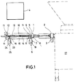
- the filling machine denoted by 17 is shown in dash-dot lines, from which the filling material continuously exits in the form of a strand and is filled into the casing in the usual manner.
- the sausage skein 5 thus created is conveyed through the central opening of a brake ring 1, which can be set in rotation by a calibration gear 2 and thereby rotates the sausage skein 5 as well.
- the addrive gear 2 is driven by an electric motor 3, which is controlled by an electronic control 4.
- the sausage strand 5 in the illustrated embodiment reaches a compartment device which consists of two displacement units 6.
- the two displacement units 6 are connected to an electric motor 7, which is also speed-controlled by the electronic control 4.
- the electric motor 7 is assembled with a gear 18, which has two drive shafts 8.
- a displacement element 9 is attached to each drive shaft 8 and is rigidly connected to it (not shown in detail).
- the compartment device is followed by a transport device which consists of two endless conveyor belts 10.
- the conveyor belts 10 are guided around deflection wheels 11, of which which are connected as drive wheels to a speed-controllable electric motor 12, which in turn is controlled by the electronic control 4.
- the conveyor belts 10 run in the opposite direction and transport the divided sausages 13 in the direction of the arrow 14.
- the sausages 13 are prevented from rotating by the conveyor belts 10.
- the drive of the separating device consists of two drive shafts 19 which are arranged in parallel at a distance from one another, opposite the sausage chain, and rotate synchronously in opposite directions and are arranged transversely to the transport direction of the sausage chain.
- each separating arm 20 or 20 ' is arranged radially opposite one another at the end of each drive shaft 19.
- Each separating arm 20 or 20 ' carries at its free end a knife 22 which is directed radially outward with its cutting edge 21.
- the drive shafts 19 are part of a transmission 23 which is assembled with an electric motor 24 whose speed can be electronically controlled by the controller 4.
- the separating device designated overall by 25, can thus be constructed in exactly the same way as the displacement unit 6.
- the separating device 25 can be controlled by the controller 4, for example, as a function of the displacing unit 6.
- the flight circles 26 and 27 of the knives 22 overlap, the overlap advantageously being approximately 1 to 2 mm.
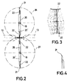
- FIG. 3 shows how the knives 22 meet in the separation area and interact in the process.
- the knives 22 are in an inclined position of the separating arms 20 and 20 ′, the ends of the knives 22 already confronting a constriction between two sausages 13 in such an inclined position.
- the two interacting knives 22 are shown shortly before the separating cut and shortly thereafter in dash-dotted lines in successive positions.
- the knives can approach to a minimum distance of approximately 0.1 mm.
- One of the knives 22 is slightly offset from the other so that they pass through the separation position one behind the other.
- An angle of approximately 20 ° formed by the two cutting surfaces has proven particularly useful.
- the cutting surfaces can be ground symmetrically, as shown in Figure 3.
- the grinding can also be done on one side, as shown in Figure 4, for example.
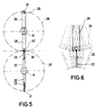
- one of the drive axles 19 is again provided with two diametrically opposed, radially outwardly projecting separating arms 20 and 20 ', each with a knife 22.
- the other drive axis 19 has two counterholders 28 and 28 ', which also project radially outward on opposite sides. They each have an open-ended recess 29 or 29 'at the end, which opens into an open slot 30 or 30'.
- the slot 30 or 30 has a width of approximately 1 to 2 mm, the cutting edge 21 of the respective knife 22 immersing approximately 1 mm in the slot 30 or 30'.
- This position of the knife 22 or the counter-holder 28 ' is shown schematically in FIG.
- the various positions of the knives and counterholders before and after the cut are shown in dash-dotted lines.
- edge-open recess 29 or 20 'and the counter-holder 28 or 28' makes it possible to manufacture the counter-holder from plastic.
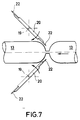
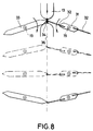
- one of the drive axles 19 carries at least one separating arm 31, to which a knife 32 is fastened, which can be made of strip steel, for example, ie the knife 32 is designed to be resilient.
- the cutting edge 35 of the knife 32 is represented by a bevel on one side.
- At least one counter-holder 33 is attached to the other drive shaft 19 and has an inclined surface 34.
- the interaction of the knife edge 35 with the inclined surface 34 is shown in FIG. 8.
- the cutting edge 35 approaches the oblique surface 34 at the constriction point.
- the separating arm 31 and the counter-holder 33 form an obtuse angle with their center lines.
- the cutting edge 35 hits the inclined surface 34 and moves forward thereon until the knife 32 is in an extended position with the center line of the counter-holder 33.
- the cutting edge 35 rests resiliently on the inclined surface 34 due to the design of the knife 32 as a leaf spring.
- the counter-holder 33 is chamfered at its front end relative to the inclined surface 34 in such a way that an edge 37 results, which can also be designed as a cutting edge.
- this bevel designated 38 also has the advantage that the sausages are not damaged in their end regions when the separating arms engage.
- the entire device works as follows:
- the sausage strand 5 coming from the filling machine 17 is set in rotation by the brake ring 1, which is driven by the electric motor 3 via the transmission 2.
- the oppositely rotating displacement elements 9 come into engagement with the sausage strand 5, their speed being regulated in such a way that the rotational speed of their crossing point essentially coincides with the advancing speed of the sausage strand 5, which is forced by the endless belts 10.
- the sausage strand 5 rotates as it is narrowed by the displacement elements 9 until the front, already twisted end of the sausage 13 is gripped by the endless belts 10 and a further constriction occurs in the following portion. After the rear sausage strand 5 rotates further, the rear end of the sausage is twisted off.
- the electronic control 4 regulates the rotational speed of the displacement elements 9, depending on the length in which the sausages are to be produced.
- the divided but coherent sausages are fed between the endless conveyor belts 10 to the separating device 25.
- the speed of the electric motor 24 of the separating device 25 can be regulated or controlled by the electronic control 4 during the rotation of the separating arms.
- the separating device for example the knives 22, reach the cutting position exactly at the desired constriction between two sausages 13, they can be controlled accordingly depending on the position of the displacement elements 9.
- the speed of rotation of the separating arms 20 can be controlled by the control device 4 so that either a separation occurs with each constriction or only after passing through a group of sausages in a certain number. Then the control device 4 regulates the rotational speed of the separating arms 20 correspondingly far during their non-functional partial circulation, possibly down to zero.
- the length of the separator arms i.e. the flight circle diameter 26 of the cutting edges 21 depends on the caliber of the sausages to be separated. For calibers between 13 and 40 mm, a flight circle diameter of approximately 80 mm and smaller has proven to be very advantageous because sausage calibers can be used as a basis in a relatively wide range of variations. with larger calibres the flight circle diameter should be correspondingly larger. Compared to previously known separation devices, a significantly higher number of portions can be separated per minute.
- the maximum possible separation performance depends on the following parameters: Portion length Conveyor belt speed Number of consecutive servings Center distance of the shafts with the separating elements Number of separators per shaft (1 or 2) Pressure angle of the separating elements in the sausage skein Maximum permissible radial acceleration or Delay.
- the drive for the endless conveyor belts 10 in the form of the electric motor 12 can of course be regulated in its speed by the controller 4, as can the electric motor 3 driving the twisting mechanism 2 as shown in the figure. In this way, all movements can be programmed to be optimally coordinated.
- the speed curve is accelerated or decelerated outside the area of engagement of the separating elements or displacement elements.
- the drive is stopped for a certain time in a reference position.
Landscapes
- Life Sciences & Earth Sciences (AREA)
- Engineering & Computer Science (AREA)
- Wood Science & Technology (AREA)
- Zoology (AREA)
- Food Science & Technology (AREA)
- Processing Of Meat And Fish (AREA)
- Meat, Egg Or Seafood Products (AREA)
- Auxiliary Devices For And Details Of Packaging Control (AREA)
Priority Applications (1)
| Application Number | Priority Date | Filing Date | Title |
|---|---|---|---|
| AT91100465T ATE98428T1 (de) | 1990-01-31 | 1991-01-16 | Verfahren und vorrichtung zum herstellen von wuersten in einer zusammenhaengenden kette und zum trennen in einzelne wuerste oder in gruppen von zusammenhaengenden wuersten. |
Applications Claiming Priority (2)
| Application Number | Priority Date | Filing Date | Title |
|---|---|---|---|
| DE9001075U DE9001075U1 (de) | 1990-01-31 | 1990-01-31 | Vorrichtung zum Herstellen von Würsten in einer zusammenhängenden Kette und zum Trennen derselben |
| DE9001075U | 1990-01-31 |
Publications (2)
| Publication Number | Publication Date |
|---|---|
| EP0440039A1 EP0440039A1 (de) | 1991-08-07 |
| EP0440039B1 true EP0440039B1 (de) | 1993-12-15 |
Family
ID=6850536
Family Applications (1)
| Application Number | Title | Priority Date | Filing Date |
|---|---|---|---|
| EP91100465A Expired - Lifetime EP0440039B1 (de) | 1990-01-31 | 1991-01-16 | Verfahren und Vorrichtung zum Herstellen von Würsten in einer zusammenhängenden Kette und zum Trennen in einzelne Würste oder in Gruppen von zusammenhängenden Würsten |
Country Status (9)
| Country | Link |
|---|---|
| US (1) | US5145450A (cs) |
| EP (1) | EP0440039B1 (cs) |
| JP (1) | JPH0811034B2 (cs) |
| AT (1) | ATE98428T1 (cs) |
| CA (1) | CA2034975A1 (cs) |
| CS (1) | CS23091A3 (cs) |
| DD (1) | DD298346A5 (cs) |
| DE (2) | DE9001075U1 (cs) |
| ES (1) | ES2049052T3 (cs) |
Cited By (2)
| Publication number | Priority date | Publication date | Assignee | Title |
|---|---|---|---|---|
| EP0931458A1 (de) | 1998-01-21 | 1999-07-28 | ALBERT HANDTMANN Maschinenfabrik GmbH & Co. KG | Vorrichtung und Verfahren zum Trennen von Würsten |
| EP0941662A2 (de) | 1998-03-09 | 1999-09-15 | ALBERT HANDTMANN Maschinenfabrik GmbH & Co. KG | Vorrichtung und Verfahren zum Trennen von Würsten |
Families Citing this family (14)
| Publication number | Priority date | Publication date | Assignee | Title |
|---|---|---|---|---|
| US5330382A (en) * | 1992-10-05 | 1994-07-19 | Marlen Research Corporation | Sizer adapter apparatus and method for creating substantially evenly and incompletely filled casings |
| JP3760472B2 (ja) * | 1995-06-13 | 2006-03-29 | ハイテック株式会社 | 充填ケーシングを、捻り部を介して分割されたソーセージ等のリンク状製品にする装置 |
| US5709600A (en) * | 1996-03-27 | 1998-01-20 | Townsend Engineering Company | Method and means for linking and then separating encased sausage |
| IT1290475B1 (it) * | 1997-03-26 | 1998-12-04 | Righele Giovanni | Macchina per produrre salsicce con budello attorcigliato |
| DE10012149B4 (de) * | 2000-03-14 | 2004-07-01 | Christof Stimpfl | Vorrichtung und Verfahren zum Abtrennen von Würsten von einem Wurststrang |
| FR2819993A1 (fr) * | 2001-02-01 | 2002-08-02 | Vemag Maschinenbau Gmbh | Procede et dispositif pour le transport et la separation de saucisses ou de produits alimentaires |
| DE10237909B4 (de) * | 2002-08-14 | 2007-08-16 | Stimpfl & Gieseler Gmbh | Vorrichtung zum Durchtrennen der Verbindung zwischen zwei Würsten |
| NL1025005C2 (nl) * | 2003-12-12 | 2005-06-14 | Townsend Engineering B V | Werkwijze voor het gefaseerd separeren van een worststreng, separatie-element en samenstel van separatie-elementen. |
| DK1886572T3 (da) * | 2006-08-10 | 2011-10-24 | Handtmann Albert Maschf | Pølsetarmbremse, der kan indstilles under produktion |
| EP1902622B1 (de) * | 2006-09-19 | 2009-01-07 | Albert Handtmann Maschinenfabrik GmbH & Co. KG | Vorrichtung und Verfahren zum Abteilen eines gefüllten Wurststrangs |
| FR2915656B1 (fr) * | 2007-05-02 | 2009-10-02 | Nijal Soc Par Actions Simplifi | Dispositif de mise en portions avec pinces et lame de coupe |
| CN107242601A (zh) * | 2016-10-28 | 2017-10-13 | 衡阳智源农业科技有限公司 | 一种塞肉菜灌肉装置 |
| DE102019106758B4 (de) * | 2019-03-18 | 2024-09-12 | Maschinenfabrik Seydelmann Kg | Schneidvorrichtung; Separierer; Verfahren zum Separieren von Lebensmittelbestandteilen mittels eines Separierers |
| DE102022117135B3 (de) | 2022-07-08 | 2023-08-03 | Vemag Maschinenbau Gmbh | Trennvorrichtung zum Trennen von Portionen aus mit Lebensmittel-Masse befüllten länglichen Hüllen, betreffendes Crimpelement sowie Verfahren |
Family Cites Families (8)
| Publication number | Priority date | Publication date | Assignee | Title |
|---|---|---|---|---|
| DE2302297C2 (de) * | 1973-01-18 | 1983-08-04 | Karl 7065 Winterbach Schnell | Vorrichtung zum Einfüllen teigiger Medien in einen Darm oder dergleichen |
| DE2402817A1 (de) * | 1974-01-22 | 1975-07-24 | Handtmann Albert Fa | Verfahren und vorrichtung zum herstellen von wuersten |
| DE3104099A1 (de) * | 1981-02-06 | 1982-09-09 | Karl 7065 Winterbach Schnell | "wurstfuellmaschine mit vorrichtung zur zipfelbildung" |
| DE3323659A1 (de) * | 1983-07-01 | 1985-01-03 | Karl 7065 Winterbach Schnell | Fuellmaschine fuer teigige medien, insbesondere fuer wurtstbraet |
| DE3408859A1 (de) * | 1984-03-10 | 1985-09-12 | Karl 7065 Winterbach Schnell | Wurstfuellmaschine mit einer vorrichtung zur zipfelbildung und einer abschneideinrichtung fuer die wuerste |
| US4730367A (en) * | 1985-09-26 | 1988-03-15 | Envaril, S.A. | Apparatus and method for producing sausages |
| DE3911859A1 (de) * | 1989-04-11 | 1990-10-18 | Handtmann Albert Maschf | Verfahren und vorrichtung zum abteilen eines von einer fuellmaschine kommenden durchgehenden wurststranges in einzelne wuerste |
| JP2612491B2 (ja) * | 1989-04-28 | 1997-05-21 | ハイテック株式会社 | ソーセージ等の製造装置 |
-
1990
- 1990-01-31 DE DE9001075U patent/DE9001075U1/de not_active Expired - Lifetime
- 1990-07-17 DD DD90342855A patent/DD298346A5/de not_active IP Right Cessation
-
1991
- 1991-01-16 DE DE91100465T patent/DE59100699D1/de not_active Expired - Lifetime
- 1991-01-16 EP EP91100465A patent/EP0440039B1/de not_active Expired - Lifetime
- 1991-01-16 AT AT91100465T patent/ATE98428T1/de not_active IP Right Cessation
- 1991-01-16 ES ES91100465T patent/ES2049052T3/es not_active Expired - Fee Related
- 1991-01-25 CA CA002034975A patent/CA2034975A1/en not_active Abandoned
- 1991-01-30 US US07/648,519 patent/US5145450A/en not_active Expired - Lifetime
- 1991-01-31 CS CS91230A patent/CS23091A3/cs unknown
- 1991-01-31 JP JP3010615A patent/JPH0811034B2/ja not_active Expired - Lifetime
Cited By (4)
| Publication number | Priority date | Publication date | Assignee | Title |
|---|---|---|---|---|
| EP0931458A1 (de) | 1998-01-21 | 1999-07-28 | ALBERT HANDTMANN Maschinenfabrik GmbH & Co. KG | Vorrichtung und Verfahren zum Trennen von Würsten |
| US6045445A (en) * | 1998-01-21 | 2000-04-04 | Albert Handtmann Maschinenfabrik Gmbh & Co. | Device and a method of separating sausages |
| EP0941662A2 (de) | 1998-03-09 | 1999-09-15 | ALBERT HANDTMANN Maschinenfabrik GmbH & Co. KG | Vorrichtung und Verfahren zum Trennen von Würsten |
| US6080054A (en) * | 1998-03-09 | 2000-06-27 | Albert Handtmann Maschinenfabrik Gmbh & Co. Kg | Device and process for separating sausages |
Also Published As
| Publication number | Publication date |
|---|---|
| EP0440039A1 (de) | 1991-08-07 |
| DD298346A5 (de) | 1992-02-20 |
| JPH0811034B2 (ja) | 1996-02-07 |
| DE59100699D1 (de) | 1994-01-27 |
| CA2034975A1 (en) | 1991-08-01 |
| DE9001075U1 (de) | 1990-09-27 |
| ATE98428T1 (de) | 1994-01-15 |
| CS23091A3 (en) | 1992-04-15 |
| US5145450A (en) | 1992-09-08 |
| JPH04218328A (ja) | 1992-08-07 |
| ES2049052T3 (es) | 1994-04-01 |
Similar Documents
| Publication | Publication Date | Title |
|---|---|---|
| EP0440039B1 (de) | Verfahren und Vorrichtung zum Herstellen von Würsten in einer zusammenhängenden Kette und zum Trennen in einzelne Würste oder in Gruppen von zusammenhängenden Würsten | |
| EP0392083B1 (de) | Verfahren und Vorrichtung zum Abteilen eines von einer Füllmaschine kommenden durchgehenden Wurststranges in einzelne Würste | |
| EP0941662B1 (de) | Vorrichtung und Verfahren zum Trennen von Würsten | |
| EP0931458B1 (de) | Vorrichtung und Verfahren zum Trennen von Würsten | |
| EP3400805A1 (de) | Vorrichtung und verfahren zum übergeben und einlegen von würstchengruppen in eine verpackung | |
| EP1902622A1 (de) | Vorrichtung und Verfahren zum Abteilen eines gefüllten Wurststrangs | |
| DE102012201915B3 (de) | Längsförderer für stabförmige Produkte der Tabak verarbeitenden Industrie und Fördereinrichtung mit einem Längsförderer und Verfahren zum Betreiben eines Längsförderers | |
| EP1767096B1 (de) | Vorrichtung und Verfahren zum Portionieren eines Gutstranges | |
| EP3449730B1 (de) | Vorrichtung zum abteilen von schlauchförmigen hüllen | |
| EP0472825A1 (de) | Vorrichtung zum Abteilen eines von einer Füllmaschine kommenden durchgehenden Wurststranges in einzelne Würste | |
| EP3967146B1 (de) | Portioniervorrichtung und -verfahren | |
| DE3315925C2 (de) | Vorrichtung zum Abschneiden von Einzelstücken | |
| EP2213177B1 (de) | Vorrichtung und Verfahren zum hüllenschonenden Abteilen von gefüllten Wurststrängen | |
| EP4014744A1 (de) | Vorrichtung und verfahren zum einschnüren und/oder abtrennen eines wurststrangs | |
| EP4133942B1 (de) | Verdrängerelementepaar | |
| DE19602411C1 (de) | Vorrichtung zum Abtrennen von Einzelstücken | |
| DE102010039479A1 (de) | Schneidvorrichtung einer Strangmaschine der Tabak verarbeitenden Industrie | |
| DE3104099A1 (de) | "wurstfuellmaschine mit vorrichtung zur zipfelbildung" | |
| EP0474970A1 (de) | Vorrichtung zum Abteilen eines von einer Füllmaschine kommenden durchgehenden Wurststranges in einzelne Würste | |
| DE709529C (de) | Querschneider | |
| DE102018132899B3 (de) | Magazinrevolvereinrichtung für Portioniermaschine | |
| DE2912247A1 (de) | Vorrichtung zum abtrennen von wuerstchen von einer kette | |
| DE2422852C3 (de) | Sammelvorrichtung für Zigaretten oder ähnliche längliche Gegenstände | |
| DE2253097C3 (de) | Zigarettenmaschine zum Herstellen von Filterzigaretten | |
| DE650409C (de) | An Strangzigarettenmaschinen angeordnete Vorrichtung zum Sondern der Zigaretten nachLage der Mundstuecke |
Legal Events
| Date | Code | Title | Description |
|---|---|---|---|
| PUAI | Public reference made under article 153(3) epc to a published international application that has entered the european phase |
Free format text: ORIGINAL CODE: 0009012 |
|
| AK | Designated contracting states |
Kind code of ref document: A1 Designated state(s): AT CH DE ES FR GB IT LI |
|
| 17P | Request for examination filed |
Effective date: 19910911 |
|
| 17Q | First examination report despatched |
Effective date: 19920908 |
|
| GRAA | (expected) grant |
Free format text: ORIGINAL CODE: 0009210 |
|
| AK | Designated contracting states |
Kind code of ref document: B1 Designated state(s): AT CH DE ES FR GB IT LI |
|
| REF | Corresponds to: |
Ref document number: 98428 Country of ref document: AT Date of ref document: 19940115 Kind code of ref document: T |
|
| ET | Fr: translation filed | ||
| REF | Corresponds to: |
Ref document number: 59100699 Country of ref document: DE Date of ref document: 19940127 |
|
| ITTA | It: last paid annual fee | ||
| GBT | Gb: translation of ep patent filed (gb section 77(6)(a)/1977) |
Effective date: 19940105 |
|
| ITF | It: translation for a ep patent filed | ||
| REG | Reference to a national code |
Ref country code: ES Ref legal event code: FG2A Ref document number: 2049052 Country of ref document: ES Kind code of ref document: T3 |
|
| PLBE | No opposition filed within time limit |
Free format text: ORIGINAL CODE: 0009261 |
|
| STAA | Information on the status of an ep patent application or granted ep patent |
Free format text: STATUS: NO OPPOSITION FILED WITHIN TIME LIMIT |
|
| 26N | No opposition filed | ||
| PGFP | Annual fee paid to national office [announced via postgrant information from national office to epo] |
Ref country code: CH Payment date: 20000131 Year of fee payment: 10 |
|
| PG25 | Lapsed in a contracting state [announced via postgrant information from national office to epo] |
Ref country code: LI Free format text: LAPSE BECAUSE OF NON-PAYMENT OF DUE FEES Effective date: 20010131 Ref country code: CH Free format text: LAPSE BECAUSE OF NON-PAYMENT OF DUE FEES Effective date: 20010131 |
|
| REG | Reference to a national code |
Ref country code: CH Ref legal event code: PL |
|
| REG | Reference to a national code |
Ref country code: GB Ref legal event code: IF02 |
|
| PGFP | Annual fee paid to national office [announced via postgrant information from national office to epo] |
Ref country code: ES Payment date: 20100121 Year of fee payment: 20 |
|
| PGFP | Annual fee paid to national office [announced via postgrant information from national office to epo] |
Ref country code: IT Payment date: 20100125 Year of fee payment: 20 Ref country code: FR Payment date: 20100210 Year of fee payment: 20 |
|
| PGFP | Annual fee paid to national office [announced via postgrant information from national office to epo] |
Ref country code: DE Payment date: 20100226 Year of fee payment: 20 Ref country code: AT Payment date: 20100122 Year of fee payment: 20 Ref country code: GB Payment date: 20100121 Year of fee payment: 20 |
|
| REG | Reference to a national code |
Ref country code: GB Ref legal event code: PE20 Expiry date: 20110115 |
|
| PG25 | Lapsed in a contracting state [announced via postgrant information from national office to epo] |
Ref country code: GB Free format text: LAPSE BECAUSE OF EXPIRATION OF PROTECTION Effective date: 20110115 |
|
| PG25 | Lapsed in a contracting state [announced via postgrant information from national office to epo] |
Ref country code: DE Free format text: LAPSE BECAUSE OF EXPIRATION OF PROTECTION Effective date: 20110116 |
|
| REG | Reference to a national code |
Ref country code: ES Ref legal event code: FD2A Effective date: 20130725 |
|
| PG25 | Lapsed in a contracting state [announced via postgrant information from national office to epo] |
Ref country code: ES Free format text: LAPSE BECAUSE OF EXPIRATION OF PROTECTION Effective date: 20110117 |