EP0439132A1 - Gerät zur magnetischen Aufzeichnung und Wiedergabe - Google Patents
Gerät zur magnetischen Aufzeichnung und Wiedergabe Download PDFInfo
- Publication number
- EP0439132A1 EP0439132A1 EP91100811A EP91100811A EP0439132A1 EP 0439132 A1 EP0439132 A1 EP 0439132A1 EP 91100811 A EP91100811 A EP 91100811A EP 91100811 A EP91100811 A EP 91100811A EP 0439132 A1 EP0439132 A1 EP 0439132A1
- Authority
- EP
- European Patent Office
- Prior art keywords
- still picture
- recording
- digital data
- magnetic tape
- signal
- Prior art date
- Legal status (The legal status is an assumption and is not a legal conclusion. Google has not performed a legal analysis and makes no representation as to the accuracy of the status listed.)
- Withdrawn
Links
Images


Classifications
-
- H—ELECTRICITY
- H04—ELECTRIC COMMUNICATION TECHNIQUE
- H04N—PICTORIAL COMMUNICATION, e.g. TELEVISION
- H04N1/00—Scanning, transmission or reproduction of documents or the like, e.g. facsimile transmission; Details thereof
- H04N1/21—Intermediate information storage
- H04N1/2104—Intermediate information storage for one or a few pictures
- H04N1/2112—Intermediate information storage for one or a few pictures using still video cameras
- H04N1/212—Motion video recording combined with still video recording
-
- H—ELECTRICITY
- H04—ELECTRIC COMMUNICATION TECHNIQUE
- H04N—PICTORIAL COMMUNICATION, e.g. TELEVISION
- H04N5/00—Details of television systems
- H04N5/76—Television signal recording
- H04N5/91—Television signal processing therefor
- H04N5/92—Transformation of the television signal for recording, e.g. modulation, frequency changing; Inverse transformation for playback
-
- G—PHYSICS
- G11—INFORMATION STORAGE
- G11B—INFORMATION STORAGE BASED ON RELATIVE MOVEMENT BETWEEN RECORD CARRIER AND TRANSDUCER
- G11B15/00—Driving, starting or stopping record carriers of filamentary or web form; Driving both such record carriers and heads; Guiding such record carriers or containers therefor; Control thereof; Control of operating function
- G11B15/02—Control of operating function, e.g. switching from recording to reproducing
- G11B15/05—Control of operating function, e.g. switching from recording to reproducing by sensing features present on or derived from record carrier or container
- G11B15/087—Control of operating function, e.g. switching from recording to reproducing by sensing features present on or derived from record carrier or container by sensing recorded signals
-
- G—PHYSICS
- G11—INFORMATION STORAGE
- G11B—INFORMATION STORAGE BASED ON RELATIVE MOVEMENT BETWEEN RECORD CARRIER AND TRANSDUCER
- G11B20/00—Signal processing not specific to the method of recording or reproducing; Circuits therefor
- G11B20/10—Digital recording or reproducing
- G11B20/10527—Audio or video recording; Data buffering arrangements
-
- G—PHYSICS
- G11—INFORMATION STORAGE
- G11B—INFORMATION STORAGE BASED ON RELATIVE MOVEMENT BETWEEN RECORD CARRIER AND TRANSDUCER
- G11B20/00—Signal processing not specific to the method of recording or reproducing; Circuits therefor
- G11B20/10—Digital recording or reproducing
- G11B20/18—Error detection or correction; Testing, e.g. of drop-outs
- G11B20/1806—Pulse code modulation systems for audio signals
-
- G—PHYSICS
- G11—INFORMATION STORAGE
- G11B—INFORMATION STORAGE BASED ON RELATIVE MOVEMENT BETWEEN RECORD CARRIER AND TRANSDUCER
- G11B27/00—Editing; Indexing; Addressing; Timing or synchronising; Monitoring; Measuring tape travel
- G11B27/10—Indexing; Addressing; Timing or synchronising; Measuring tape travel
- G11B27/102—Programmed access in sequence to addressed parts of tracks of operating record carriers
- G11B27/107—Programmed access in sequence to addressed parts of tracks of operating record carriers of operating tapes
-
- G—PHYSICS
- G11—INFORMATION STORAGE
- G11B—INFORMATION STORAGE BASED ON RELATIVE MOVEMENT BETWEEN RECORD CARRIER AND TRANSDUCER
- G11B27/00—Editing; Indexing; Addressing; Timing or synchronising; Monitoring; Measuring tape travel
- G11B27/10—Indexing; Addressing; Timing or synchronising; Measuring tape travel
- G11B27/19—Indexing; Addressing; Timing or synchronising; Measuring tape travel by using information detectable on the record carrier
- G11B27/28—Indexing; Addressing; Timing or synchronising; Measuring tape travel by using information detectable on the record carrier by using information signals recorded by the same method as the main recording
- G11B27/30—Indexing; Addressing; Timing or synchronising; Measuring tape travel by using information detectable on the record carrier by using information signals recorded by the same method as the main recording on the same track as the main recording
- G11B27/3027—Indexing; Addressing; Timing or synchronising; Measuring tape travel by using information detectable on the record carrier by using information signals recorded by the same method as the main recording on the same track as the main recording used signal is digitally coded
-
- H—ELECTRICITY
- H04—ELECTRIC COMMUNICATION TECHNIQUE
- H04N—PICTORIAL COMMUNICATION, e.g. TELEVISION
- H04N1/00—Scanning, transmission or reproduction of documents or the like, e.g. facsimile transmission; Details thereof
- H04N1/21—Intermediate information storage
- H04N1/2104—Intermediate information storage for one or a few pictures
- H04N1/2112—Intermediate information storage for one or a few pictures using still video cameras
- H04N1/2137—Intermediate information storage for one or a few pictures using still video cameras with temporary storage before final recording, e.g. in a frame buffer
-
- H—ELECTRICITY
- H04—ELECTRIC COMMUNICATION TECHNIQUE
- H04N—PICTORIAL COMMUNICATION, e.g. TELEVISION
- H04N5/00—Details of television systems
- H04N5/76—Television signal recording
- H04N5/91—Television signal processing therefor
- H04N5/92—Transformation of the television signal for recording, e.g. modulation, frequency changing; Inverse transformation for playback
- H04N5/928—Transformation of the television signal for recording, e.g. modulation, frequency changing; Inverse transformation for playback the sound signal being pulse code modulated and recorded in time division multiplex with the modulated video signal
-
- H—ELECTRICITY
- H04—ELECTRIC COMMUNICATION TECHNIQUE
- H04N—PICTORIAL COMMUNICATION, e.g. TELEVISION
- H04N5/00—Details of television systems
- H04N5/76—Television signal recording
- H04N5/91—Television signal processing therefor
- H04N5/93—Regeneration of the television signal or of selected parts thereof
- H04N5/94—Signal drop-out compensation
- H04N5/945—Signal drop-out compensation for signals recorded by pulse code modulation
-
- H—ELECTRICITY
- H04—ELECTRIC COMMUNICATION TECHNIQUE
- H04N—PICTORIAL COMMUNICATION, e.g. TELEVISION
- H04N9/00—Details of colour television systems
- H04N9/79—Processing of colour television signals in connection with recording
- H04N9/7921—Processing of colour television signals in connection with recording for more than one processing mode
-
- H—ELECTRICITY
- H04—ELECTRIC COMMUNICATION TECHNIQUE
- H04N—PICTORIAL COMMUNICATION, e.g. TELEVISION
- H04N9/00—Details of colour television systems
- H04N9/79—Processing of colour television signals in connection with recording
- H04N9/87—Regeneration of colour television signals
-
- G—PHYSICS
- G11—INFORMATION STORAGE
- G11B—INFORMATION STORAGE BASED ON RELATIVE MOVEMENT BETWEEN RECORD CARRIER AND TRANSDUCER
- G11B2220/00—Record carriers by type
- G11B2220/90—Tape-like record carriers
-
- H—ELECTRICITY
- H04—ELECTRIC COMMUNICATION TECHNIQUE
- H04N—PICTORIAL COMMUNICATION, e.g. TELEVISION
- H04N2101/00—Still video cameras
Definitions
- the present invention relates to a magnetic recording and reproducing apparatus, for example, a video tape recorder (hereinafter abbreviated to VTR), which can record both continuous moving pictures and a still picture for each frame or field.
- VTR video tape recorder
- a recording track on a magnetic tape has a general moving picture analog recording area by two-head helical scan and also an overlap recording area (commonly called) on the extension thereof.
- the overlap recording area can be formed by winding the magnetic tape round the rotary head drum in an about 220° arc and is generally used to record PCM audio signals.
- a VTR combined with video camera is provided with a digital-electronic still camera function in addition to a general moving picture analog recording function.
- An object of the present invention is to provide a magnetic recording and reproducing apparatus wherein the reproducing operations of the apparatus are improved so that convenient operations for the user are secured.
- a magnetic recording and reproducing apparatus which comprises a rotary drum, a magnetic head mounted to the rotary drum, a mechanism for traveling a magnetic tape so as to wind round the rotary drum in a more than 180° arc, a circuit for recording a moving picture signal and an audio signal for the moving picture on a first area in a recording track inclined to a magnetic tape traveling direction, a circuit for recording digital data indicating a one-cut still picture signal corresponding to a frame or a field on a second area in the recording track, a circuit for reproducing the moving picture signal, a circuit for reproducing said audio signal for the moving picture, a circuit for reproducing the still picture signal, a circuit for detecting that the digital data indicating the still picture is reproduced by an amount of data corresponding to the one cut of the still picture, a switch which is operated by a person who monitors pictures so as to instruct the restart of the magnetic tape, and a logic circuit which generates an instruction for switching the reproducing signal output from the
- Fig. 2 is a block diagram showing a recording circuit of a VTR combined with video camera which is used in the present invention.
- the above VTR conforms to the 8 mm video standard.
- processing such as generation of luminance and color-difference signals and color encoding is performed digitally as described hereunder.
- processing such as generation of luminance and color-difference signals and color encoding is performed digitally as described hereunder.
- processing may be performed analogically.
- Light passing through a lens tube 103 forms an optical image on a solid-state image sensor 104.
- the light receiving surface of the image sensor has photodiodes corresponding to the number of scanning lines (the NTSC specifies 525 scanning lines), which are lined up in the vertical direction, and photodiodes corresponding to the number of pixels per line, which are lined up in the horizontal direction.
- the output thereof is supplied to an A-D converter 105 to be converted to a digital image signal.
- an example of a signal of a sampling frequency of 4f sc (a symbol f sc indicates a frequency of a color subcarrier which is 455/2 x 4.5/286 ⁇ 3.579545 MHz) and a quantization bit number of 8 is shown.
- the output of the A-D converter is supplied to an encoder circuit 106, and processing such as generation of luminance and color-difference signals and color subcarrier modulation with two color-difference signals is performed digitally. Then, the output is supplied to a D-A converter 107 and a frame or field memory 108.
- the output of the D-A converter 107 is an analog video signal which conforms to the NTSC standard and supplied to a luminance signal recording circuit 116 and a chrominance signal recording circuit 115 of the VTR unit.
- the output is also supplied to a viewfinder 112 via a switch 110 to display moving pictures which are being imaged.
- the switch 110 When the VTR unit is in the stopped or recording state, the switch 110 is connected to the PB position as shown in Fig. 2. When the VTR unit is in the reproducing state, the switch is connected to the PB position (on the opposite side) . In the latter case, a reproduced video signal is supplied from the VTR unit via an input terminal 111 to the view finder 112.
- a logic signal generated from a one-shot switch 109 mounted on the outer surface of the apparatus is also applied to the frame (or field) memory 108.
- This signal specifies the moment the user records a still picture (foregoing overlap recording) .
- Data of the first frame (or field) after the switch 109 is pressed is stored in the memory 108 as still picture information. It is required that the data is read at a frequency of 2f H which is the same as the sampling frequency of an audio signal which will be described later as an example.
- one-field imaging causes no problems.
- one-frame imaging causes problems such as blurring of a moving object due to interlace scanning.
- An audio signal collected by a microphone 101 is amplified by a microphone amplifier 102 and supplied to a noise reduction circuit 113 of the VTR.
- the audio signal supplied to the noise reduction circuit 113 is provided with a non-linear high-frequency band emphasis characteristic and then supplied to an audio signal recording circuit 114 and an A-D converter 117.
- the audio signal is modulated to an FM audio signal with a carrier frequency of about 1.5 MHz and supplied to one end of an adder 125A.
- the audio signal is converted to a digital audio signal, for example, with a sampling frequency of 2f H (a symbol f H indicates a horizontal synchronizing frequency which is 4500/286 ⁇ 15.734 kHz) and a quantization bit count of 8 (10 bits are provided actually and compressed to 8 bits after quantization), and supplied to one end of a switch 118.
- a sampling frequency of 2f H (a symbol f H indicates a horizontal synchronizing frequency which is 4500/286 ⁇ 15.734 kHz) and a quantization bit count of 8 (10 bits are provided actually and compressed to 8 bits after quantization), and supplied to one end of a switch 118.
- the luminance signal component of the foregoing analog video signal outputted from the D-A converter 107 is modulated to an FM luminance signal with a carrier frequency of, for example, about 5 MHz by the luminance signal recording circuit 116, and the chrominance signal component is down converted to a subcarrier frequency of about 47.25 f H by the chrominance signal recording circuit 115, and both signals are supplied to one end of the adder 125A.
- a pilot signal whose frequency is switched cyclically in the order of 6.5 f H , 7.5 f H , 10.5 f H , and 9.5 f H for each field on the basis of the synchronizing signal which is separated by the luminance signal recording circuit 116 and a tach pulse indicating the rotation phase of a rotary head drum which will be described later is generated and supplied to another end of the adder 125A.
- This is a tracking control signal for reproduction.
- the above four signals which are frequency-division multiplexed by the adder 125A are supplied to one end of a switch 126.
- the switch 118 is switched according to the position of a bistable switch 119 which can be externally switched.
- the switch 119 is used by the user to select recording PCM audio signals in the foregoing overlap recording area or recording still pictures digitally.
- the A-D converter 117 and the switches 118 and 119 are removed, and the output of the memory 108 is directly connected to a data addition circuit 120.
- data addition circuit 120 data address information, an identification code (a code for identifying voice or a still picture, etc.), and a parity code for error correction during reproduction are added to the output, and then the output is stored in a buffer memory 121.
- the time axis is compressed so that the output becomes an intermittent signal which can be recorded in the overlap area.
- the 8-bit parallel data is converted to serial data, added with a CRC code for detecting an error during reproduction, and changed to a channel code which is called a biphase mark in a pulse code modulation circuit 123.
- the channel code is added with a pilot signal by an adder 125B and supplied to another end of the switch 126.
- the output of the switch 126 is recorded on a magnetic tape 136 by a recording head 135 (two heads are provided actually) via a recording amplifier 127.
- the recording head 135 is mounted on a rotary drum (not shown in the figure).
- the rotary drum is rotated by a drum motor 129, and the rotation is controlled by a result of phase comparison by a drum servo circuit 131 between the output of a tach pulse generator 130 indicating the rotation phase and the foregoing synchronizing signal (only vertical) .
- the output of the tach pulse generator 130 which is shaped by a switch pulse generator 128, the output of the foregoing adder 125A can be recorded on the main track of the magnetic tape 136 and the output of the foregoing adder 125B on the extended overlap recording track.
- the magnetic tape 136 travels as a capstan motor 132 rotates.
- the travel is controlled by a capstan servo circuit 134 on the basis of the output pulse of a frequency generator 133 which indicates the rotation phase of the capstan motor 132, resulting in a constant rate of travel specified by the VTR standard.
- the coding method for overlap recording signals is as specified by the current audio 8-bit PCM standard. However, it is not a necessary condition. There are possibilities that the number of bits increases in the future, and the coding method may conform to such an increased number of bits. In either way, it is convenient if the data addition circuit 120 and subsequent circuits can be shared. By doing this, a system wherein the section comprising the memory 108 and the switch 109 and the section comprising the A-D converter 117 shown in Fig. 2 are separated from the main unit, and the switches 118 and 119 are eliminated, and one of the separated sections mentioned above is mounted according to an application can be realized. This can contribute to miniaturization of the main unit.
- Fig. 3 is a plan view showing a rotary head drum 138.
- an arrow 138d indicates the rotation direction of the rotary head drum 138
- an arrow 136d the traveling direction of the magnetic tape 136.
- the recording head 135 comprises two recording heads 135A and 135B, which are mounted opposite to each other.
- the magnetic tape 136 is positioned by guide rollers 137A and 137B so that it is wound round the rotary head drum 138 in a 210° arc (actually 220 to 230° including a margin). Therefore, the recording pattern on the magnetic tape is as shown in Fig. 4.
- Continuous moving pictures are recorded during the winding period of about 180° and one-cut digital still pictures (and a pilot signal) are recorded on the overlap recording area of the residual about 30°.
- moving pictures are recorded in a field per track in the order of A1, A2, B1, B2, --- shown in the figure. If a one-frame still picture is recorded during the overlap period, it requires a large number of tracks.
- the current 8-bit PCM standard specifies a data amount of 8400 bits/track. Since a frame is 3.8 Mb (in the case of composite quantization) long for 4 f sc and 8-bit quantization, about 450 tracks, that is, a time of about 7.5 seconds is required.
- the configuration and operation of the apparatus depend on how to output moving and still pictures during reproduction.
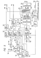
- FIG. 5 is a circuit block diagram showing an embodiment of the present invention in such a case. The components which are the same as those used for recording in Fig. 2 are assigned the same numbers.
- a signal which is reproduced from the magnetic tape 136 by the reproducing head 135 (the recording head 135 shown in Fig. 2 may be used) is amplified by a reproducing amplifier 139 and supplied to a switch 140.
- the rotary head drum (not shown in the figure) where the reproducing head 135 is mounted is rotated by the drum motor 129.
- the output of the tach pulse generator 130 indicating the rotation phase is supplied to the drum servo circuit 131, which allows the drum motor 129 to rotate at a constant speed (30 rps) .
- the switch 140 is switched and driven by the output of the tach pulse generator 130 which is shaped by the switch pulse generator 128, and continuous moving pictures (and an FM audio signal and a pilot signal) during the foregoing winding period of about 180° are obtained at the terminal on the "a" side in the figure, and signals (a PCM audio signal or one-cut digital still pictures and a pilot signal) in the overlap recording area of the residual about 30° at the terminal on the "b" side.
- the signal at the "a" terminal is supplied to an audio signal reproducing (demodulation) circuit 141, a chrominance signal reproducing circuit 143, a luminance signal reproducing circuit 144, and a pilot signal reproducing circuit 146.
- a tracking error signal is returned to the capstan servo circuit 134 on the basis of the beat component of the pilot signal for the current and neighboring tracks so that the reproducing head 135 traces the tracks in the same way as recording.
- an FM audio signal with a carrier frequency of about 1.5 MHz is extracted to be frequency-demodulated, provided with a non-linear high-frequency band attenuation characteristic by a noise reduction circuit 142 (reverse characteristics to 113 shown in Fig. 2) so as to improve the signal-to-noise ratio, returned to the initial audio signal, and supplied to one end of a switch 149.
- a noise reduction circuit 142 reverse characteristics to 113 shown in Fig. 2
- a chrominance signal with a subcarrier of about 47.25 f H is returned to the initial band (455/2 f H with the phase variation component eliminated, and supplied to one end of an adder 145.
- an FM luminance signal is demodulated to the initial signal, and supplied to another end of the adder 145.
- the luminance and chrominance signals which are added by the adder 145 are outputted to an output terminal 151 via a character insertion circuit 147 whose operation will be described later so as to display moving pictures on an external television set.
- the luminance and chrominance signals are also supplied to the input terminal 111 shown in Fig. 2, and moving pictures can be monitored by the viewfinder 112.
- the signal at the "b" terminal of the switch 140 is corrected in the frequency characteristics provided by the tape head system by a reproducing equalizer 152, and returned to a digital signal with the base band by a pulse code demodulator 154 after reproducing data is resampled by a data strobe circuit 153. Then, a data error caused by drop-out of the tape system is detected by an error detection circuit 155 on the basis of the CRC code assigned for recording, and the digital signal is returned to parallel (for example, 8 bits) data by a serial-to-parallel converter 156 and written into a buffer memory 165.
- the data is read by a clock signal with a frequency of, for example, 2f H , and the data error is corrected by an error correction circuit 157 on the basis of an instruction from the error detection circuit 155.
- the reproduced signal is an audio signal or a still picture is discriminated by the identification code assigned for recording, and information on the frame (or field) start and end points when the reproduced signal is a still picture is obtained from the address.
- the output of the error correction circuit 157 is supplied to a D-A converter 158 and the frame (or field) memory 108.
- the D-A converter 158 is used to return an audio signal which is PCM-recorded to an analog signal, and the output thereof is supplied to another end of the switch 149.
- the switch 149 is driven according to the foregoing discrimination result by the identification code.
- the identification code indicates that the reproduced signal is an audio signal
- the audio signal which is PCM-recorded is outputted to an output terminal 150 in a priority basis. (Because the tone quality is better than that for FM recording.)
- the identification code indicates that the reproduced signal is a still picture, an audio signal which is FM-recorded is outputted.
- One-cut still picture data is stored in the memory 108, converted to an analog signal by a D-A converter 159, outputted to an output terminal 160, and then supplied to an external printer.
- the memory 108 may be interfaced with the printer in the digital mode unless the D-A converter 159 is used.
- An output terminal 163 is an output terminal of a printing instruction signal to the printer.
- a printing instruction is generated and outputted by a first logic circuit 161 on the basis of the foregoing address (and the identification code). It is needless to say that before one cut is stored, printing may start when some scanning lines are stored. The printer requires several minutes for printing one color image. If the next still picture information appears before the printing is finished and the memory 108 is rewritten, the normal printing is impossible. For that reason, a printing end signal from the printer is inputted via an input terminal 164 and supplied to the memory 108 and a second logic circuit 162.
- the second logic circuit 162 sends an instruction to the capstan servo circuit 134 and the character insertion circuit 147.
- the capstan servo circuit 134 rewinds the magnetic tape 136 to near the start point of the next still picture data on the basis of this instruction, and keeps the magnetic tape stopped until the current printing is finished.
- the character insertion circuit 147 character-multiplexes the information stored in a ROM 148 onto moving pictures on the basis of this instruction, and notifies the user that the tape is kept stopped until the printing is finished, keeping him away from a strange impression.
- the above operation is performed when the memory 108 serves as a printer memory.
- the printer has a memory, it is desirable to perform the same operation when still picture data after additional one cut is reproduced before a printing end signal instruction is issued.
- the user can obtain all the required still pictures printed.
- a monitor television set may be connected to the output terminal 160, or a still picture may be superimposed onto a signal supplied to the output terminal 151 (picture in picture) or switched by using a switch which is installed so as to be operated by the user.
- moving and still pictures are obtained from an output terminal, and can be monitored on the screen of a television set. It is possible that while moving pictures are being displayed, still pictures are displayed only when still picture data is found, the magnetic tape is rewound to near the still picture start position during that period and stopped there, and the magnetic tape starts traveling when an instruction is issued by the user so as to display moving pictures once again, or moving pictures are always displayed continuously and a part thereof is cut off so as to display still pictures one by one (so called picture in picture), or a part of still pictures is cut off inversely so as to display moving pictures.
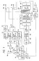
- An embodiment of the first case will be described with reference to the circuit block diagram shown in Fig. 1. Many components are the same as those shown in Fig. 5, except that an one-shot type switch 1, a switch 2 and a third logic circuit 3 are installed.
- the switch 2 is generally connected in the direction shown in the figure and sends moving pictures to the output terminal 151 to a television set.
- the switch 2 is connected in the opposite direction by an instruction from the third logic circuit 3 and sends still pictures recorded in the overlap area.
- the capstan servo circuit 134 rewinds the magnetic tape 136 to near the still picture data start position and keeps the tape stopped there also by an instruction from the third logic circuit 3.
- the switch 2 is connected in the direction shown in the figure once again also by an instruction from the third logic circuit 3, and the capstan servo circuit 134 restarts tape traveling so as to reproduce moving pictures once again as usual.
- the tape traveling restarts automatically so as to reproduce moving pictures once again. It is also possible that before reproduced data of still picture are stored by one cut in the memory 108, the reproduced data are outputted so as gradually to display a still picture of one cut in the same way as the first embodiment.
- Fig. 1 When the configuration shown in Fig. 1 is used, moving and still pictures can be monitored by a television set. Though one-cut still picture requires a recording and reproducing time of about 10 seconds as mentioned above, the foregoing rewinding and stopping operation for displaying still pictures eliminates a time skip for returning to moving pictures from still pictures.
- an output terminal for the printer is not installed particularly unlike the embodiment shown in Fig. 5.
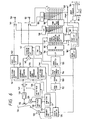
- an output terminal may be installed as shown in the circuit block diagram in Fig. 6.
- the first one of differences between Fig. 6 and Fig. 5 is that an output terminal 5 of still pictures to the printer is a digital interface, whereby analog and digital signals are not converted repeatedly so as to prevent the picture quality from degradation.
- the second difference is that the switch 2 is installed in the same way as Fig. 1 so as to switch and output moving pictures or still pictures to a monitor television set.
- the third difference is that an AND circuit 4 is installed, and the general reproduction of moving pictures restarts after the printing of still pictures is finished and the user instructs returning to the reproduction of moving pictures.
- the user selects moving pictures or still pictures.
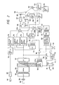
- the embodiment will be described with reference to the circuit block diagram shown in Fig. 7.
- a bistable switch 6 which is operated by the user is installed. By using the bistable switch 6, whether to output moving pictures or still pictures to the output terminal 151 to a monitor television set is selected by the switch 2.
- the output of the switch 6 is also connected to the second logic circuit 162 so as to switch the operation of the capstan servo circuit 134.
- the general reproducing operation is performed.
- the capstan servo circuit 134 enters the search mode, and allows the magnetic tape 136 to travel at a high speed so as to search for the location where the first still picture data is recorded.
- the capstan servo circuit 134 detects the location from the reproduction address, rewinds the tape a little immediately, and performs the general reproducing operation starting at the beginning of the recorded still picture data.
- the capstan servo circuit 134 enters the search mode once again and searches for the location where the next still picture data is stored.
- the capstan servo circuit 134 detects the location, it rewinds the tape a little immediately.
- the capstan servo circuit 134 keeps the tape stopped at the location until the printing end instruction is issued.
- the capstan servo circuit 134 performs the same operation when the tape reaches the location where the still picture data after additional one cut is recorded. Then, the capstan servo circuit 134 performs the general reproducing operation and reads one-cut data.
- the embodiment shown in Fig. 7 is suited to still pictures which are required to be printed quickly. It is possible that units equivalent to the switch 1 and the AND circuit 4 shown in Fig. 6 are installed and the time required for starting the next one cut after the printing is finished is optionally set. As to output of still pictures to be sent to the monitor television set from the output terminal 151, previous images may be outputted continuously during the searching operation, and a previous image may be gradually rewritten by the next still picture during the general reproducing operation.
- the same may be said with a case where the input and output terminals 160, 163, and 164 between the apparatus and the printer are not installed.
- the printing operation is automatically performed. However, only data to be printed may be selected.
- the present invention improves the reproducing operations of an apparatus wherein one-cut still pictures are recorded at an optional location of the overlap recording area of a 8 mm video VTR.
- whether to watch moving pictures or still pictures (or to print still pictures) can be selected, and in the latter case, the location where still pictures are recorded is searched for at a high speed, and the searching operation is restarted after printing. Therefore, the printing output may be obtained quickly and correctly.
- the time that still pictures are displayed can be optionally selected, and no strange feeling (frame skipping) is provided when moving pictures are restarted.
Applications Claiming Priority (2)
| Application Number | Priority Date | Filing Date | Title |
|---|---|---|---|
| JP12548/90 | 1990-01-24 | ||
| JP2012548A JP2753361B2 (ja) | 1990-01-24 | 1990-01-24 | 磁気録画再生装置 |
Publications (1)
| Publication Number | Publication Date |
|---|---|
| EP0439132A1 true EP0439132A1 (de) | 1991-07-31 |
Family
ID=11808389
Family Applications (1)
| Application Number | Title | Priority Date | Filing Date |
|---|---|---|---|
| EP91100811A Withdrawn EP0439132A1 (de) | 1990-01-24 | 1991-01-23 | Gerät zur magnetischen Aufzeichnung und Wiedergabe |
Country Status (4)
| Country | Link |
|---|---|
| US (1) | US5351154A (de) |
| EP (1) | EP0439132A1 (de) |
| JP (1) | JP2753361B2 (de) |
| KR (1) | KR940006730B1 (de) |
Cited By (5)
| Publication number | Priority date | Publication date | Assignee | Title |
|---|---|---|---|---|
| EP0444837A2 (de) * | 1990-02-27 | 1991-09-04 | Sony Corporation | Videosignalaufnahmegerät |
| EP0518069A2 (de) * | 1991-05-14 | 1992-12-16 | Canon Kabushiki Kaisha | Bildwiedergabesystem |
| EP0642274A2 (de) * | 1993-09-06 | 1995-03-08 | Sony Corporation | Gerät zur Aufzeichnung und Wiedergabe eines Videosignals |
| US5589943A (en) * | 1991-08-20 | 1996-12-31 | Canon Kabushiki Kaisha | Apparatus for recording digital still image signals and analog still image signals in respective recording areas |
| DE4222903C2 (de) * | 1992-07-11 | 2003-04-10 | Leifheit Ag | Bügeltisch |
Families Citing this family (3)
| Publication number | Priority date | Publication date | Assignee | Title |
|---|---|---|---|---|
| AU682032B2 (en) * | 1993-06-29 | 1997-09-18 | Sony Corporation | Audio signal transmitting apparatus and the method thereof |
| US6205283B1 (en) * | 1995-10-17 | 2001-03-20 | Canon Kabushiki Kaisha | Image processing apparatus responsive to single input for image reproduction and printing |
| JP4207869B2 (ja) * | 2004-08-30 | 2009-01-14 | ソニー株式会社 | 再生制御方法及び再生装置 |
Citations (5)
| Publication number | Priority date | Publication date | Assignee | Title |
|---|---|---|---|---|
| DE3042274A1 (de) * | 1980-11-08 | 1982-05-13 | Grundig E.M.V. Elektro-Mechanische Versuchsanstalt Max Grundig & Co KG, 8510 Fürth | Verfahren und videoanlage zur wahlweisen aufzeichnung von aus zwei halbbildern bestehenden einzel- und laufbildern |
| DE3310998A1 (de) * | 1982-03-25 | 1983-09-29 | Sony Corp., Tokyo | Videosignal-aufzeichnungsgeraet |
| US4604668A (en) * | 1980-11-21 | 1986-08-05 | Lemelson Jerome H | Portable television camera and recording unit |
| EP0316770A2 (de) * | 1987-11-13 | 1989-05-24 | Polaroid Corporation | System und Verfahren zur Formatierung eines zusammengesetzten elektronischen Informationssignals, das stillstehende und bewegte Bilder definiert |
| US4858032A (en) * | 1986-06-30 | 1989-08-15 | Fuji Photo Film Co., Ltd. | Device for extracting still picture frames from a moving image video signal and recording same on a magnetic recording medium |
Family Cites Families (2)
| Publication number | Priority date | Publication date | Assignee | Title |
|---|---|---|---|---|
| JPS6233367A (ja) * | 1985-08-07 | 1987-02-13 | Hitachi Ltd | 磁気記録再生装置 |
| JPH0240105A (ja) * | 1988-07-30 | 1990-02-08 | Toshiba Corp | ビデオ信号記録装置 |
-
1990
- 1990-01-24 JP JP2012548A patent/JP2753361B2/ja not_active Expired - Lifetime
-
1991
- 1991-01-18 KR KR1019910000792A patent/KR940006730B1/ko not_active IP Right Cessation
- 1991-01-23 EP EP91100811A patent/EP0439132A1/de not_active Withdrawn
- 1991-01-24 US US07/645,395 patent/US5351154A/en not_active Expired - Fee Related
Patent Citations (5)
| Publication number | Priority date | Publication date | Assignee | Title |
|---|---|---|---|---|
| DE3042274A1 (de) * | 1980-11-08 | 1982-05-13 | Grundig E.M.V. Elektro-Mechanische Versuchsanstalt Max Grundig & Co KG, 8510 Fürth | Verfahren und videoanlage zur wahlweisen aufzeichnung von aus zwei halbbildern bestehenden einzel- und laufbildern |
| US4604668A (en) * | 1980-11-21 | 1986-08-05 | Lemelson Jerome H | Portable television camera and recording unit |
| DE3310998A1 (de) * | 1982-03-25 | 1983-09-29 | Sony Corp., Tokyo | Videosignal-aufzeichnungsgeraet |
| US4858032A (en) * | 1986-06-30 | 1989-08-15 | Fuji Photo Film Co., Ltd. | Device for extracting still picture frames from a moving image video signal and recording same on a magnetic recording medium |
| EP0316770A2 (de) * | 1987-11-13 | 1989-05-24 | Polaroid Corporation | System und Verfahren zur Formatierung eines zusammengesetzten elektronischen Informationssignals, das stillstehende und bewegte Bilder definiert |
Cited By (15)
| Publication number | Priority date | Publication date | Assignee | Title |
|---|---|---|---|---|
| EP0444837A2 (de) * | 1990-02-27 | 1991-09-04 | Sony Corporation | Videosignalaufnahmegerät |
| US6061497A (en) * | 1990-02-27 | 2000-05-09 | Sony Corporation | Video signal recording apparatus |
| EP0444837A3 (en) * | 1990-02-27 | 1993-03-31 | Sony Corporation | Video signal recording apparatus |
| US5926285A (en) * | 1991-05-14 | 1999-07-20 | Canon Kabushiki Kaisha | Image reproduction system for reproducing a still image from a video |
| EP0899739A2 (de) * | 1991-05-14 | 1999-03-03 | Canon Kabushiki Kaisha | Bildwiedergabesystem |
| EP0518069A3 (de) * | 1991-05-14 | 1995-02-15 | Canon Kk | |
| EP0518069A2 (de) * | 1991-05-14 | 1992-12-16 | Canon Kabushiki Kaisha | Bildwiedergabesystem |
| EP0899739A3 (de) * | 1991-05-14 | 2004-02-25 | Canon Kabushiki Kaisha | Bildwiedergabesystem |
| US7298515B2 (en) | 1991-05-14 | 2007-11-20 | Canon Kabushiki Kaisha | Image reproduction system for reproducing a still image from a video tape |
| US5589943A (en) * | 1991-08-20 | 1996-12-31 | Canon Kabushiki Kaisha | Apparatus for recording digital still image signals and analog still image signals in respective recording areas |
| DE4222903C2 (de) * | 1992-07-11 | 2003-04-10 | Leifheit Ag | Bügeltisch |
| EP0642274A2 (de) * | 1993-09-06 | 1995-03-08 | Sony Corporation | Gerät zur Aufzeichnung und Wiedergabe eines Videosignals |
| EP0642274A3 (de) * | 1993-09-06 | 1995-04-26 | Sony Corp | Gerät zur Aufzeichnung und Wiedergabe eines Videosignals. |
| US5659654A (en) * | 1993-09-06 | 1997-08-19 | Sony Corporation | Apparatus for recording and/or reproducing a video signal |
| US5933572A (en) * | 1993-09-06 | 1999-08-03 | Sony Corporation | Apparatus for recording and/or reproducing a video signal |
Also Published As
| Publication number | Publication date |
|---|---|
| KR940006730B1 (ko) | 1994-07-27 |
| JPH03218189A (ja) | 1991-09-25 |
| US5351154A (en) | 1994-09-27 |
| KR910014873A (ko) | 1991-08-31 |
| JP2753361B2 (ja) | 1998-05-20 |
Similar Documents
| Publication | Publication Date | Title |
|---|---|---|
| US5097363A (en) | Still image signal recording and reproducing apparatus having greater feeder speed when searching | |
| EP0253192B1 (de) | Gerät zur magnetischen Aufzeichnung und Wiedergabe | |
| US5307171A (en) | Video tape recorder/player | |
| US5589943A (en) | Apparatus for recording digital still image signals and analog still image signals in respective recording areas | |
| EP0487092B1 (de) | Breitbild Videoaufnahme-/Wiedergabesystem | |
| US5351154A (en) | Magnetic recording and reproducing apparatus | |
| US5202798A (en) | Still image signal recording apparatus operable by a manually operable member | |
| US5130860A (en) | Video signal recording apparatus | |
| EP0405491A2 (de) | Gerät zur Aufzeichnung und Wiedergabe eines digitalen Standbildsignals | |
| US5461485A (en) | Video camera with selective compensation for still picture recording in response to shutter operation | |
| US5585934A (en) | Video signal recording apparatus capable of motion-image and still-image recording | |
| KR0119115B1 (ko) | 비디오프린팅제어기가 내장된 비디오테이프레코너 | |
| JP2000069407A (ja) | 画像記録再生装置 | |
| KR930009177B1 (ko) | 화상재생장치 및 방법 | |
| JP3154761B2 (ja) | 画像再生装置及び画像記録装置 | |
| EP0506436B1 (de) | Facsimilegerät mit einem Schraubenabtastung VCR | |
| KR100239251B1 (ko) | 비디오신호기록장치 | |
| JP3094428B2 (ja) | 映像信号記録装置 | |
| JP2535948B2 (ja) | 画像記録システム | |
| JP3554584B2 (ja) | 静止画及び動画記録用の一体形ビデオカメラ及び再生装置 | |
| JPH03218188A (ja) | 磁気録画装置及びこれを用いる磁気録画再生装置 | |
| JPH0614727B2 (ja) | 磁気記録装置 | |
| JP2985252B2 (ja) | 映像信号記録装置 | |
| JPS5820084A (ja) | 電子式静止画像記録再生装置 | |
| KR100268384B1 (ko) | 영상신호기록방법 |
Legal Events
| Date | Code | Title | Description |
|---|---|---|---|
| PUAI | Public reference made under article 153(3) epc to a published international application that has entered the european phase |
Free format text: ORIGINAL CODE: 0009012 |
|
| 17P | Request for examination filed |
Effective date: 19910123 |
|
| AK | Designated contracting states |
Kind code of ref document: A1 Designated state(s): DE GB |
|
| 17Q | First examination report despatched |
Effective date: 19931116 |
|
| STAA | Information on the status of an ep patent application or granted ep patent |
Free format text: STATUS: THE APPLICATION HAS BEEN WITHDRAWN |
|
| 18W | Application withdrawn |
Withdrawal date: 19940325 |