EP0438383B1 - Revêtement en béton précontraint dans une galerie en pression - Google Patents
Revêtement en béton précontraint dans une galerie en pression Download PDFInfo
- Publication number
- EP0438383B1 EP0438383B1 EP91810018A EP91810018A EP0438383B1 EP 0438383 B1 EP0438383 B1 EP 0438383B1 EP 91810018 A EP91810018 A EP 91810018A EP 91810018 A EP91810018 A EP 91810018A EP 0438383 B1 EP0438383 B1 EP 0438383B1
- Authority
- EP
- European Patent Office
- Prior art keywords
- anchorage
- pass
- lining concrete
- bodies
- concrete according
- Prior art date
- Legal status (The legal status is an assumption and is not a legal conclusion. Google has not performed a legal analysis and makes no representation as to the accuracy of the status listed.)
- Expired - Lifetime
Links
Images


Classifications
-
- E—FIXED CONSTRUCTIONS
- E04—BUILDING
- E04C—STRUCTURAL ELEMENTS; BUILDING MATERIALS
- E04C5/00—Reinforcing elements, e.g. for concrete; Auxiliary elements therefor
- E04C5/08—Members specially adapted to be used in prestressed constructions
- E04C5/12—Anchoring devices
-
- E—FIXED CONSTRUCTIONS
- E02—HYDRAULIC ENGINEERING; FOUNDATIONS; SOIL SHIFTING
- E02B—HYDRAULIC ENGINEERING
- E02B9/00—Water-power plants; Layout, construction or equipment, methods of, or apparatus for, making same
- E02B9/02—Water-ways
- E02B9/06—Pressure galleries or pressure conduits; Galleries specially adapted to house pressure conduits; Means specially adapted for use therewith, e.g. housings, valves, gates
-
- E—FIXED CONSTRUCTIONS
- E04—BUILDING
- E04G—SCAFFOLDING; FORMS; SHUTTERING; BUILDING IMPLEMENTS OR AIDS, OR THEIR USE; HANDLING BUILDING MATERIALS ON THE SITE; REPAIRING, BREAKING-UP OR OTHER WORK ON EXISTING BUILDINGS
- E04G21/00—Preparing, conveying, or working-up building materials or building elements in situ; Other devices or measures for constructional work
- E04G21/12—Mounting of reinforcing inserts; Prestressing
-
- E—FIXED CONSTRUCTIONS
- E21—EARTH DRILLING; MINING
- E21D—SHAFTS; TUNNELS; GALLERIES; LARGE UNDERGROUND CHAMBERS
- E21D11/00—Lining tunnels, galleries or other underground cavities, e.g. large underground chambers; Linings therefor; Making such linings in situ, e.g. by assembling
- E21D11/04—Lining with building materials
- E21D11/10—Lining with building materials with concrete cast in situ; Shuttering also lost shutterings, e.g. made of blocks, of metal plates or other equipment adapted therefor
- E21D11/107—Reinforcing elements therefor; Holders for the reinforcing elements
-
- E—FIXED CONSTRUCTIONS
- E04—BUILDING
- E04G—SCAFFOLDING; FORMS; SHUTTERING; BUILDING IMPLEMENTS OR AIDS, OR THEIR USE; HANDLING BUILDING MATERIALS ON THE SITE; REPAIRING, BREAKING-UP OR OTHER WORK ON EXISTING BUILDINGS
- E04G21/00—Preparing, conveying, or working-up building materials or building elements in situ; Other devices or measures for constructional work
- E04G21/12—Mounting of reinforcing inserts; Prestressing
- E04G2021/127—Circular prestressing of, e.g. columns, tanks, domes
-
- Y—GENERAL TAGGING OF NEW TECHNOLOGICAL DEVELOPMENTS; GENERAL TAGGING OF CROSS-SECTIONAL TECHNOLOGIES SPANNING OVER SEVERAL SECTIONS OF THE IPC; TECHNICAL SUBJECTS COVERED BY FORMER USPC CROSS-REFERENCE ART COLLECTIONS [XRACs] AND DIGESTS
- Y02—TECHNOLOGIES OR APPLICATIONS FOR MITIGATION OR ADAPTATION AGAINST CLIMATE CHANGE
- Y02E—REDUCTION OF GREENHOUSE GAS [GHG] EMISSIONS, RELATED TO ENERGY GENERATION, TRANSMISSION OR DISTRIBUTION
- Y02E10/00—Energy generation through renewable energy sources
- Y02E10/20—Hydro energy
Definitions
- the present invention relates to a prestressed concrete lining in a pressure gallery according to the preamble of claim 1.
- An examination carried out beforehand usually shows in which sub-areas of a pressure tunnel to be created in the mountains which lining is to be selected.
- the lining of pressure tunnels represents a shell that is embedded in the mountain material (rock).
- the rock material as an enveloping abutment is at the same time a component of the overall construction.
- the static relationships in this composite body require an assessment of the various load influences. For this reason, a decision must be made before the execution, for example, whether the nature of the mountains and the mountain superimposition allow the rock to participate.
- the milling technology for creating the tunnel as well as the formwork and concreting technology have developed in such a way that the work for the installation of steel armor with concrete backfilling or the use of the prestressed concrete lining can less and less follow the work progress.
- it is desirable that the above-mentioned construction methods for creating linings can be quickly adapted to unforeseen and / or changing rock conditions. Due to the usual delivery times, it is hardly possible to meet this need to create additional steel armor.
- With the prestressed concrete lining there is basically nothing to stand in the way of adaptability.
- this task is performed by the characterizing part of claim 1 listed features solved.
- 1 to 4 show anchoring bodies which are preferably used in the production of pressure tunnels. However, they can also be used in the production of curved walls, for example containers.
- 1 and 2, 1 shows a first embodiment of one of the anchoring bodies. It consists of an elongated body made of reinforced concrete. In cross section, the body is essentially U-shaped, has two legs 2, 3, which are oriented in the same direction and are spaced apart and are connected to one another at their base by a base leg 4. Each of the legs 2, 3 is designed such that there are a plurality of first through openings 5 running in its transverse direction for the passage of one tendon each. The first through openings 5 are more or less in relation to the longitudinal direction of the two legs 2, 3 regularly spaced from each other.
- the anchor plate is provided so that an anchor sleeve can be placed on it for prestressing the tendon guided through the first through opening 5.
- FIG. 2 which shows a cross section through the anchoring body of FIG. 1, the anchor plates are each connected to a first through tube 9. Since both the anchor plate 8 and the through tube 9 are each made of a steel material, the connection mentioned is preferably a welded connection.
- second through openings 10 running in the transverse direction to the anchoring body 1, which are lined with second, preferably steel, through tubes 11.
- second through openings 10 are also arranged at more or less regular intervals along the anchoring body. These second through openings 10 are also intended for the passage of tendons, as will be shown further below.
- the first and second through-tubes 9, 11 advantageously protrude to form a reinforcement joint with reinforcement abutting the anchoring body.
- the anchor plate 8 with the welded-on first through tube 9 together forms part of a tension anchor.
- the through tubes 9 and 11 in the anchoring body 1 are also intended for partial reinforcement.
- With 14 are in the longitudinal direction running openings, in which pipes are also arranged, shown. These also serve for the partial reinforcement of the anchoring body and for the passage of tension rods or tendons, for the longitudinal prestressing of several anchoring bodies arranged one behind the other. Additional reinforcements are not shown in the figures.
- FIG. 3 shows the cross section of a second embodiment of an anchoring body 15.
- This second embodiment of an anchoring body 15 is particularly suitable for the production of pressure tunnels.
- the outer surface 18 of the base leg 4 is rounded, preferably with a radius that roughly corresponds to that of the pressure tunnel to be created.
- the inner surfaces 16, 17 of the two legs 2, 3 are inclined to one another in a V-shape. Distributed over the height of each of the legs 2, 3, two stacked anchor plates 8 and first through tubes 9 are arranged in this embodiment.
- the direction of exit of the first through tubes 9 from the anchoring body 15 can be determined.
- This is preferably selected in such a way that it is shown in more detail further below that the tendons running around the pressure gallery are subject to the smallest possible changes in radius in order to avoid additional friction losses.
- This also applies to the arrangement of the second through-tubes 11, which is also held in this anchoring body in such a way that the tendons carried out flow as smoothly as possible into a pressure tunnel radius Skip tendon radius.
- the second through-tubes 11 likewise have an anchor plate 8 on one side. This is intended to create an anchoring sleeve to form a firm anchoring of the tendons to be carried out later.
- FIG. 4 shows a third embodiment of an anchoring body 19. It has essentially the same shape as that which is shown in FIGS. 1 and 2. Instead of the lead-through openings 9, 10, however, incisions 20, 21 are formed in this exemplary embodiment, which are intended to lead through the tendons. Each of the tendons can also be passed through a through tube 9, which is welded on one side to an anchor plate 8 and inserted into one of the incisions 20. The through tube 9 with the anchor plate 8 also forms part of a tension anchor here and can also be used for the partial reinforcement of the anchor body, in particular after concreting the same. As in the first exemplary embodiment, second through-tubes 11, which are inserted into the lower incisions 21, can be used to lead tendons through the base leg 4.
- FIG. 5 shows a fourth embodiment of an anchoring body 22 which is essentially L-shaped in cross section.
- One leg 23 has a first through-opening 5 running in its transverse direction for the passage of a tendon.
- This through opening is also designed analogously to FIGS. 1 and 2 with an anchor plate 8 and a first through tube 9.
- the anchor plate 8 and the through tube 9 are also welded together, have been concreted into the anchoring body 22, form parts of a tension anchoring and are also intended for partial reinforcement of the anchoring body.
- In the other leg 24 there are further through openings 10 which run approximately parallel to the through opening 5. Pipes, namely second passage pipes 11, are also present in these passage openings.
- This anchoring body which is particularly suitable for the production of plates, ceilings, beams and shells, corresponds essentially to the anchoring body 1, which has been described with reference to FIGS. 1 and 2, the leg 3 not being formed.
- anchoring bodies not described here, for example also made of materials other than reinforced concrete, are possible for the most diverse applications in prestressing technology and the most varied structures.
- anchoring bodies in pressure tunnel construction is primarily described, since the advantageous features mentioned at the outset are particularly effective there.
- FIG. 6 shows a cross section through a pressure gallery 30 before the floor is introduced.
- the rock surrounding the pressure gallery is designated by 31, 32 identifies reinforcement elements, for example reinforcement baskets, such as those usually created for reinforcing pressure galleries, over their circumference distributed, and are preferably attached by means of rock plugs 33 in the rock 31.
- 34 denotes a rod which forms the reinforcement joint between two adjacent reinforcement baskets.
- Anchoring bodies 15, of which only the end face of one is visible in the figure and which have been prefabricated beforehand or during the rock eruption when the pressure tunnel was created, preferably outside the tunnel, are strung together with the progressive rock eruption in the pressure tunnel, longitudinally connected to one another by prestressing and serve as Sole part 35.
- the two legs 2, 3 are designed in such a way that rails 37, which serve to advance construction machinery along the tunnel, can be mounted on each of their surfaces facing away from the base.
- the groove 45 located between the inner surfaces of the two legs is used during the construction of the pressure gallery as a trench for water drainage.
- tendons 40, 41 are through one leg of the Anchoring body 15 of the anchoring block 36 passed through, run along the pressure tunnel wall opposite the first-mentioned tendons, to the anchoring body 15 of the sole part 35, cross there through the second through openings 10 and end, for example at a distance from the anchoring body 35 in a fixed anchoring 43
- Distances of the legs and dimensions of the anchoring body 15 used are dimensioned such that, after concreting, a prestressing press can be attached to the prestressing anchors 42 for prestressing the tendons.
- the tendons can be prestressed individually with the anchoring bodies practically without the above-mentioned friction losses. As a result, smaller sized presses can be used. It can also be seen from FIG. 6 that the anchoring bodies can be constructed in such a way that the tendons can be laid practically with a constant radius. This also has a positive effect on keeping the friction losses small.
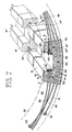
- FIG. 7 shows a perspective representation of anchoring bodies 15, 15 'and 15'', which have served as sole part 35 when the pressure tunnel was created.
- the tension anchorages are again identified and with 43 the fixed anchorages.
- the tendons 38, 39, 40, 41 described above are also visible in the figure.
- a further tendon is indicated, on the basis of which the insertion into the anchoring body 15 and the pretension can be explained.
- the tensioning member 46 which in this example is shown as a single strand with a plastic sheathing, is inserted into the first through opening 5, the plastic sheath is cut at a location 47 which lies outside the anchoring body 15. The tendon is then inserted into the associated first through opening 5 of the anchoring body 15 and protrudes on the inside of the corresponding leg.
- the incision is now located, for example, at location 47 'within the metal tube 9.
- the foremost plastic sheath is removed and an anchor sleeve 48 is pushed over the exposed strand 49.
- the cable is pretensioned with a clamping press and wedged in the clamping sleeve.
- the end of the plastic sheathing is now in place 47 ′′ just in front of the anchor sleeve 48.
- the remaining cavity 63 between the anchor sleeve and the plastic sheath is filled with an injection compound.
- the grooves 45 can be concreted and adapted to the concrete wall 62.
- FIG. 7 also shows pretensioning rods 50, 50 ', with which a plurality of anchoring bodies 15, 15', 15 '', which are arranged in series, are connected to one another under pretension, for example during the pressure tunnel excavation.
- a connection point of two anchoring bodies 15, 15 ' is shown in more detail in FIG. 8, for example.
- the longitudinal opening 14 'of the anchoring body 15' has, for example, an extension 52 at one end into which an anchor plate 53 is inserted shortly before the additional anchoring body 15 is attached or during the manufacture of the anchoring body in the concrete is poured.
- the tension rod 50 'passed through the anchor plate 53 is prestressed in a known manner and, for example, has been wedged with the anchor plate 53.
- the end of the tension rod 50 ' has, for example, a thread via which a rod coupling nut 54 is screwed.
- This nut is dimensioned such that it fits into the longitudinal opening 14 of the anchoring body 15 which is now to be attached.
- a further tension rod 50 is pushed through the passage opening 14 and screwed into the rod coupling nut 54 until it bears against the rod 50 ′.
- An adhesive mortar is preferably applied to the abutting surfaces between two anchoring bodies 15, 15 '.
- the further rod 50 can then be pretensioned as already described. In this way, the anchoring blocks formed from a plurality of anchoring bodies are created.
- FIG. 9 also shows the arrangement of anchoring bodies according to FIG. 5 described above after the creation of a flat plate or ceiling.
- Anchoring bodies 56 are arranged on both sides of the ceiling, some of which can rest on a supporting structure 57.
- a first tendon 58 has a fixed anchor 60 at its right end in the figure, is guided through the right anchor body 56 and ends in a tendon anchor 61 of the left tendon 56.
- a second tendon 59 ends on its left side in a fixed anchor 60, is passed through the left anchoring body 56 and ends on its right side in a tension anchoring 61 of the right anchoring body 56.
- the ceiling 55 is drawn in the finished state without formwork.
- the other necessary reinforcing bars are not shown.
- curved plates or walls can be prestressed in a relatively simple and cost-saving manner by using anchoring bodies.
Claims (11)
- Habillage de béton précontraint dans une galerie en pression, comportant plusieurs éléments d'armature (32) répartis sur la périphérie longitudinalement à la galerie en pression et reliés au minimum en partie entre eux par des éléments de tension (38, 39, 40, 41) qui englobent au minimum une partie de la périphérie de la galerie en pression avec des ancrages de tension (42) pour tendre les éléments de tension, les ancrages de tension étant au minimum accessibles pendant la construction de la galerie en pression à partir de l'intérieur de celle-ci, de même qu'avec une partie semelle (35) s'étendant le long de la galerie en pression, laquelle partie semelle est constituée par plusieurs éléments indépendants disposés en ordre contigu, dont les surfaces latérales sont respectivement voisines des éléments d'armature, caractérisé en ce que chacun des différents éléments est un corps d'ancrage (1, 15, 19), que chacun des corps d'ancrage présente une section essentiellement en U, que dans chacun des montants (2, 3) des corps d'ancrage regardant l'intérieur de la galerie existent les premiers moyens (5, 20) de passage d'au minimum respectivement un des éléments de tension (38, 39, 40, 41), une plaque d'ancrage (8) étant disposée sur les surfaces intérieures se regardant des montants dans le domaine de chacun des premiers moyens de passage (5, 20), qu'il existe dans le montant de base un second moyen (10, 21) pour le passage d'au minimum respectivement un des éléments de tension (38, 39, 40, 41) et que chacun des éléments de tension (38, 39, 40, 41) et qu'en partant d'un ancrage fixe (43), soit guidé par un des deux moyens de passage (10, 21) d'un des corps d'ancrage et aboutisse, après avoir traversé un des premiers moyens de passage (5, 20) d'un des corps d'ancrage dans une douille d'ancrage (48) d'un ancrage de tension (42) appuyant sur une des plaques d'ancrage (8).
- Habillage en béton conforme à la revendication 1, caractérisé en ce que chacun des corps d'ancrage (1, 15, 19) présente dans sa direction longitudinale au minimum une ouverture traversante (14) et que les corps d'ancrage sont reliés entre eux par une précontrainte avec le moyen de tension (50) passant par les orifices mentionnés.
- Habillage en béton conforme à la revendication 1 ou 2, caractérisé en ce qu'un bloc d'ancrage (36) est constitué par d'autres corps d'ancrage (1, 15, 19) disposés l'un contre l'autre, qu'un ou plusieurs blocs d'ancrage (36) sont disposés répartis sur la périphérie de la galerie en pression, au minimum un des éléments d'armature (32) existant sur la périphérie de la galerie en pression entre deux blocs d'ancrage (36) contigus et/ou la partie semelle (35) et un bloc d'ancrage (36) contigu à celle-ci.
- Habillage en béton conforme à l'une des revendications 1 à 3, caractérisé en ce que les éléments de tension (38, 39, 40, 41) englobent des mono-torons gainés de matière plastique, pourvus d'une protection contre la corrosion continue parvenant jusque dans les premiers moyens de passage (5, 20).
- Habillage en béton conforme à l'une des revendications 1 à 3, caractérisé en ce que les éléments de tension (38, 39, 40, 41) comprennent plusieurs torons placés dans des tubes de gainage.
- Habillage en béton conforme à l'une des revendications 1 à 5, caractérisé en ce que les corps d'ancrage (1, 15, 19) sont fabriqués en béton armé et peuvent être posés dans les galeries sous pression pendant leur construction.
- Habillage en béton conforme à l'une des revendications 1 à 6, caractérisé en ce que les premiers moyens de passage (5) et/ou les seconds moyens de passage (10) des corps d'ancrage (1, 15, 19) sont des orifices de passage pourvus respectivement d'un premier tube métallique (9) et/ou respectivement d'un second (11).
- Habillage en béton conforme à l'une des revendications 1 à 6, caractérisé en ce que les premiers moyens de passage (20) et/ou les seconds moyens de passage (21) des corps d'ancrage (1, 15, 19) sont des découpes pourvues respectivement d'un premier tube métallique (9) et/ou d'un second (11).
- Habillage en béton conforme à la revendication 7 ou 8, caractérisé en ce qu'au minimum une partie des premiers tubes métalliques (9) est disposée en saillie sur le côté regardant la plaque d'ancrage (8) pour constituer un joint d'armature pour l'élément d'armature (32) contigu provenant du corps d'ancrage (1, 15, 19).
- Habillage en béton conforme à la revendication 7 ou 8, caractérisé en ce qu'au minimum une partie du deuxième tube métallique (11) est disposée en saillie pour constituer un joint d'armature pour l'élément d'armature contigu (32) au minimum sur un côté du corps d'armature (1, 15, 19).
- Habillage en béton conforme à l'une des revendications 1 à 10, caractérisé en ce que les premiers moyens de passage (5, 20) et/ou les seconds moyens de passage (10, 21) sont disposés approximativement à intervalles réguliers par rapport à la direction longitudinale de chacun des corps d'ancrage (1, 15, 19).
Applications Claiming Priority (2)
| Application Number | Priority Date | Filing Date | Title |
|---|---|---|---|
| CH17890 | 1990-01-19 | ||
| CH178/90 | 1990-01-19 |
Publications (2)
| Publication Number | Publication Date |
|---|---|
| EP0438383A1 EP0438383A1 (fr) | 1991-07-24 |
| EP0438383B1 true EP0438383B1 (fr) | 1993-05-26 |
Family
ID=4181043
Family Applications (1)
| Application Number | Title | Priority Date | Filing Date |
|---|---|---|---|
| EP91810018A Expired - Lifetime EP0438383B1 (fr) | 1990-01-19 | 1991-01-11 | Revêtement en béton précontraint dans une galerie en pression |
Country Status (6)
| Country | Link |
|---|---|
| US (1) | US5066167A (fr) |
| EP (1) | EP0438383B1 (fr) |
| JP (1) | JPH0674578B2 (fr) |
| DE (1) | DE59100123D1 (fr) |
| ES (1) | ES2041200T3 (fr) |
| PT (1) | PT96521A (fr) |
Cited By (1)
| Publication number | Priority date | Publication date | Assignee | Title |
|---|---|---|---|---|
| CN103216247A (zh) * | 2013-04-23 | 2013-07-24 | 长江勘测规划设计研究有限责任公司 | 预应力盾构隧洞及施工方法 |
Families Citing this family (16)
| Publication number | Priority date | Publication date | Assignee | Title |
|---|---|---|---|---|
| DE19528999C2 (de) * | 1995-08-07 | 2000-01-05 | Pfleiderer Verkehrstechnik | Verbindung von Spannbetonelementen und Verfahren hierzu |
| GB9929123D0 (en) * | 1999-12-10 | 2000-02-02 | James Peter | Improvements relating to tunnel reinforcements |
| US6814525B1 (en) * | 2000-11-14 | 2004-11-09 | Michael Whitsett | Piling apparatus and method of installation |
| FR2822177B1 (fr) * | 2001-03-15 | 2004-04-30 | Freyssinet Int Stup | Dispositif d'ancrage pour armatures de precontrainte, systeme de precontrainte incluant le dispositif, et armature appropriee |
| WO2009056898A1 (fr) * | 2007-11-02 | 2009-05-07 | Alejandro Cortina-Cordero | Tour en béton postcontraint pour génératrices éoliennes |
| US20100154318A1 (en) * | 2008-12-23 | 2010-06-24 | Chevron U.S.A. Inc. | Ring beam and method for constructing the same |
| US20100230207A1 (en) * | 2009-03-13 | 2010-09-16 | James Larson | Boarding bridge fall protection system |
| ES2549791T3 (es) * | 2009-05-19 | 2015-11-02 | Pacadar S.A. | Torre para una turbina eólica |
| US20100132270A1 (en) * | 2009-07-08 | 2010-06-03 | General Electric Wind Energy & Energy Services | Modular surface foundation for wind turbine space frame towers |
| IT1400073B1 (it) * | 2009-09-11 | 2013-05-17 | Stefano Knisel | Fondazione migliorata per torre eolica |
| DE102011052733B4 (de) * | 2011-08-16 | 2023-09-28 | Langenstein & Schemann Gmbh | Maschinenfundament, Verfahren zum Betrieb einer Umformmaschine und Umformanlage |
| US20130212963A1 (en) * | 2012-02-21 | 2013-08-22 | Fabcon, Inc. | Wind Turbine Tower |
| BR112015002426A2 (pt) * | 2012-08-03 | 2017-07-04 | D Lockwood James | torre de turbina de vento segmentada protendida de concreto pré-moldado |
| ES2471641B1 (es) * | 2012-12-21 | 2015-04-07 | Acciona Windpower, S.A. | Dovela prefabricada de hormigón, torre de aerogenerador que comprende dicha dovela, aerogenerador que comprende dicha torre y procedimiento de montaje de dicho aerogenerador |
| CN106401610A (zh) * | 2016-11-16 | 2017-02-15 | 河北科技大学 | 一种隧道支护结构 |
| EP3604879B1 (fr) * | 2017-03-28 | 2022-07-13 | Li Li | Pipeline de module intelligent, machine à enroulement de pipeline hélicoïdal de module intelligent et procédé d'enroulement associé |
Family Cites Families (12)
| Publication number | Priority date | Publication date | Assignee | Title |
|---|---|---|---|---|
| CH304650A (de) * | 1951-06-30 | 1955-01-31 | Dyckerhoff & Widmann Ag | Verfahren zur Herstellung einer aus Spannbeton bestehenden Auskleidung für Stollen. |
| FR1458056A (fr) * | 1962-10-26 | 1966-03-04 | Babcock & Wilcox Ltd | Perfectionnements aux enceintes sous pression en béton |
| GB1408641A (en) * | 1972-03-02 | 1975-10-01 | Charcon Tunnelshld | Tunnelling shields |
| US3824751A (en) * | 1972-06-23 | 1974-07-23 | Preload Technology | Precast concrete wall structure for waste treatment tanks |
| GB1393287A (en) * | 1972-08-15 | 1975-05-07 | Charcon Tunnels Ltd | Arcuate tunnel lining segments |
| CH559843A5 (fr) * | 1972-11-22 | 1975-03-14 | Losinger Ag | |
| US3869530A (en) * | 1974-02-19 | 1975-03-04 | Chester I Williams | Method of constructing a prestressed concrete circular wall |
| GB1507977A (en) * | 1974-03-27 | 1978-04-19 | Mott Hay & Anderson | Tunnel linings |
| US4045929A (en) * | 1975-12-01 | 1977-09-06 | Gianfranco Velo Dalbrenta | Liquidtight tank made of prestressed reinforced concrete, particularly for purification plants |
| FR2371562A1 (fr) * | 1976-11-22 | 1978-06-16 | Demay Freres Ciment Arme | Procede pour la construction de tours notamment de chateaux d'eau |
| US4497590A (en) * | 1982-03-08 | 1985-02-05 | Crs Group, Inc. | Tunnel lining |
| DE3218517C2 (de) * | 1982-05-17 | 1984-03-01 | Philipp Holzmann Ag, 6000 Frankfurt | Tübbingausbau für Tunnels, Stollen o.dgl. und Meßgerät zur Überprüfung der Fugenbreite eines derartigen Tübbingausbaues |
-
1991
- 1991-01-11 EP EP91810018A patent/EP0438383B1/fr not_active Expired - Lifetime
- 1991-01-11 ES ES199191810018T patent/ES2041200T3/es not_active Expired - Lifetime
- 1991-01-11 DE DE9191810018T patent/DE59100123D1/de not_active Expired - Fee Related
- 1991-01-11 JP JP3001973A patent/JPH0674578B2/ja not_active Expired - Lifetime
- 1991-01-11 US US07/640,234 patent/US5066167A/en not_active Expired - Fee Related
- 1991-01-18 PT PT96521A patent/PT96521A/pt not_active Application Discontinuation
Cited By (2)
| Publication number | Priority date | Publication date | Assignee | Title |
|---|---|---|---|---|
| CN103216247A (zh) * | 2013-04-23 | 2013-07-24 | 长江勘测规划设计研究有限责任公司 | 预应力盾构隧洞及施工方法 |
| CN103216247B (zh) * | 2013-04-23 | 2016-05-04 | 长江勘测规划设计研究有限责任公司 | 预应力盾构隧洞及施工方法 |
Also Published As
| Publication number | Publication date |
|---|---|
| EP0438383A1 (fr) | 1991-07-24 |
| ES2041200T3 (es) | 1993-11-01 |
| US5066167A (en) | 1991-11-19 |
| DE59100123D1 (de) | 1993-07-01 |
| JPH0674578B2 (ja) | 1994-09-21 |
| JPH0649829A (ja) | 1994-02-22 |
| PT96521A (pt) | 1992-09-30 |
Similar Documents
| Publication | Publication Date | Title |
|---|---|---|
| EP0438383B1 (fr) | Revêtement en béton précontraint dans une galerie en pression | |
| DE3734953C2 (de) | Abstandhalter für ein spannbares Zugglied | |
| DE3734954C2 (fr) | ||
| DE2717869A1 (de) | Verfahren zum herstellen von bauteilen aus spannbeton | |
| DE19735457C2 (de) | Injektions- oder Verpreßkörper | |
| DE3342746C2 (fr) | ||
| DE3838069C2 (de) | Transport- und einbetonierfähiges Spannbewehrungsaggregat für das Vorspannen von Stahlbetonbauwerken | |
| DE3806759C2 (de) | Verfahren zum Sanieren eines hohlzylindrischen Baukörpers und Bausatzsystem hierzu | |
| DE2425866A1 (de) | Kabel fuer schraegkabelbruecken aus spannbeton | |
| DE3831518C2 (de) | Spannglied in polygonartiger Anordnung sowie Verfahren zum Einziehen des Spannglieds | |
| DE4107370C2 (fr) | ||
| EP0473539B1 (fr) | Disposition de câbles de tension dans une galerie en pression | |
| AT380502B (de) | Verfahren und vorrichtung zum verbreitern von fahrbahnplatten, brueckenfahrbahnen od.dgl. | |
| DE3601587C2 (fr) | ||
| CH657651A5 (en) | Method and arrangement for constructing a retaining wall having external slabs | |
| DE19502712A1 (de) | Deckenplatte für Gebäude | |
| DE102016106290A1 (de) | Bewehrungselement | |
| DE3902777A1 (de) | Stahlblechsegment fuer einen streckenausbau | |
| LU502258B1 (de) | Verfahren zur Herstellung eines Röhrenkomplexes | |
| AT412221B (de) | Bauwerk mit wandungen mit im wesentlichen verbundfrei angeordneten spanngliedern | |
| DE1191640B (de) | Verbundrohr aus Steinzeug und Beton | |
| DE2703822A1 (de) | Verfahren zum herstellen langer bauwerke aus spannbeton im taktweisen verschiebeverfahren mit waehrend des vorschiebens wandernder, exzentrischer laengsvorspannung | |
| CH683205A5 (de) | Bauelementensatz zum Abdichten von Kanälen. | |
| EP0046818A1 (fr) | Connexion glissante à serrage pour des segments chevauchants de poutrelles des soutènements de galeries minières | |
| DE2516723A1 (de) | Verfahren zur sicherung und zum ausbau des gebirges beim tunnelvortrieb und selbsttragende ausbau- und armierungsmatte zur durchfuehrung des verfahrens |
Legal Events
| Date | Code | Title | Description |
|---|---|---|---|
| PUAI | Public reference made under article 153(3) epc to a published international application that has entered the european phase |
Free format text: ORIGINAL CODE: 0009012 |
|
| AK | Designated contracting states |
Kind code of ref document: A1 Designated state(s): CH DE ES FR IT LI |
|
| 17P | Request for examination filed |
Effective date: 19911220 |
|
| 17Q | First examination report despatched |
Effective date: 19920903 |
|
| GRAA | (expected) grant |
Free format text: ORIGINAL CODE: 0009210 |
|
| STAA | Information on the status of an ep patent application or granted ep patent |
Free format text: STATUS: THE PATENT HAS BEEN GRANTED |
|
| AK | Designated contracting states |
Kind code of ref document: B1 Designated state(s): CH DE ES FR IT LI |
|
| REF | Corresponds to: |
Ref document number: 59100123 Country of ref document: DE Date of ref document: 19930701 |
|
| ET | Fr: translation filed | ||
| ITF | It: translation for a ep patent filed |
Owner name: UFFICIO TECNICO ING. A. MANNUCCI |
|
| REG | Reference to a national code |
Ref country code: ES Ref legal event code: FG2A Ref document number: 2041200 Country of ref document: ES Kind code of ref document: T3 |
|
| PLBE | No opposition filed within time limit |
Free format text: ORIGINAL CODE: 0009261 |
|
| 26N | No opposition filed | ||
| REG | Reference to a national code |
Ref country code: CH Ref legal event code: PFA Free format text: VSL INTERNATIONAL AG |
|
| PGFP | Annual fee paid to national office [announced via postgrant information from national office to epo] |
Ref country code: FR Payment date: 20011210 Year of fee payment: 12 |
|
| PGFP | Annual fee paid to national office [announced via postgrant information from national office to epo] |
Ref country code: DE Payment date: 20011219 Year of fee payment: 12 |
|
| PGFP | Annual fee paid to national office [announced via postgrant information from national office to epo] |
Ref country code: CH Payment date: 20020116 Year of fee payment: 12 |
|
| PGFP | Annual fee paid to national office [announced via postgrant information from national office to epo] |
Ref country code: ES Payment date: 20020118 Year of fee payment: 12 |
|
| PG25 | Lapsed in a contracting state [announced via postgrant information from national office to epo] |
Ref country code: ES Free format text: LAPSE BECAUSE OF NON-PAYMENT OF DUE FEES Effective date: 20030113 |
|
| PG25 | Lapsed in a contracting state [announced via postgrant information from national office to epo] |
Ref country code: LI Free format text: LAPSE BECAUSE OF NON-PAYMENT OF DUE FEES Effective date: 20030131 Ref country code: CH Free format text: LAPSE BECAUSE OF NON-PAYMENT OF DUE FEES Effective date: 20030131 |
|
| PG25 | Lapsed in a contracting state [announced via postgrant information from national office to epo] |
Ref country code: DE Free format text: LAPSE BECAUSE OF NON-PAYMENT OF DUE FEES Effective date: 20030801 |
|
| REG | Reference to a national code |
Ref country code: CH Ref legal event code: PL |
|
| PG25 | Lapsed in a contracting state [announced via postgrant information from national office to epo] |
Ref country code: FR Free format text: LAPSE BECAUSE OF NON-PAYMENT OF DUE FEES Effective date: 20030930 |
|
| REG | Reference to a national code |
Ref country code: FR Ref legal event code: ST |
|
| REG | Reference to a national code |
Ref country code: ES Ref legal event code: FD2A Effective date: 20030113 |
|
| PG25 | Lapsed in a contracting state [announced via postgrant information from national office to epo] |
Ref country code: IT Free format text: LAPSE BECAUSE OF NON-PAYMENT OF DUE FEES;WARNING: LAPSES OF ITALIAN PATENTS WITH EFFECTIVE DATE BEFORE 2007 MAY HAVE OCCURRED AT ANY TIME BEFORE 2007. THE CORRECT EFFECTIVE DATE MAY BE DIFFERENT FROM THE ONE RECORDED. Effective date: 20050111 |