EP0436821B1 - Verfahren zur Herstellung eines Feldsteuerungsbelages für Mittelspannungsgarnituren - Google Patents
Verfahren zur Herstellung eines Feldsteuerungsbelages für Mittelspannungsgarnituren Download PDFInfo
- Publication number
- EP0436821B1 EP0436821B1 EP90122681A EP90122681A EP0436821B1 EP 0436821 B1 EP0436821 B1 EP 0436821B1 EP 90122681 A EP90122681 A EP 90122681A EP 90122681 A EP90122681 A EP 90122681A EP 0436821 B1 EP0436821 B1 EP 0436821B1
- Authority
- EP
- European Patent Office
- Prior art keywords
- weight
- process according
- solvent
- ethylene
- field control
- Prior art date
- Legal status (The legal status is an assumption and is not a legal conclusion. Google has not performed a legal analysis and makes no representation as to the accuracy of the status listed.)
- Expired - Lifetime
Links
Images

Classifications
-
- H—ELECTRICITY
- H02—GENERATION; CONVERSION OR DISTRIBUTION OF ELECTRIC POWER
- H02G—INSTALLATION OF ELECTRIC CABLES OR LINES, OR OF COMBINED OPTICAL AND ELECTRIC CABLES OR LINES
- H02G15/00—Cable fittings
- H02G15/02—Cable terminations
- H02G15/06—Cable terminating boxes, frames or other structures
- H02G15/064—Cable terminating boxes, frames or other structures with devices for relieving electrical stress
- H02G15/068—Cable terminating boxes, frames or other structures with devices for relieving electrical stress connected to the cable shield only
-
- Y—GENERAL TAGGING OF NEW TECHNOLOGICAL DEVELOPMENTS; GENERAL TAGGING OF CROSS-SECTIONAL TECHNOLOGIES SPANNING OVER SEVERAL SECTIONS OF THE IPC; TECHNICAL SUBJECTS COVERED BY FORMER USPC CROSS-REFERENCE ART COLLECTIONS [XRACs] AND DIGESTS
- Y10—TECHNICAL SUBJECTS COVERED BY FORMER USPC
- Y10T—TECHNICAL SUBJECTS COVERED BY FORMER US CLASSIFICATION
- Y10T29/00—Metal working
- Y10T29/49—Method of mechanical manufacture
- Y10T29/49002—Electrical device making
- Y10T29/49227—Insulator making
Definitions
- the invention relates to a method for producing a field control covering from a polymer material and an electrically conductive additive with an end closure for medium voltages.
- Field-controlling elements for cable fittings are known in many ways.
- a large number of fillers are used as the main active ingredients, which in combination with a suitable polymer matrix and possibly other additives form the field-controlling element.
- Such fillers are, for example, inorganic substances with a high dielectric constant such as titanium (IV) compounds (titanium dioxide, barium titanate), electrically conductive additives such as silicon carbide, carbon black, metal powder and metal and semimetal oxides (zinc oxide, aluminum oxide, boron oxide, iron (II, III) -oxide).
- 70% iron (II, III) oxide which is embedded in a polymer matrix made of butyl rubber, is often used as the main active ingredient.
- This product is applied as an inner coating in a heat-shrinkable tube.
- such a combination of materials has disadvantages in long-term use, especially after high transient overvoltages have occurred. After that, the requirements were often no longer met.
- a sealing compound of the type mentioned above is provided as the field-controlling element, which is used as an inner coating in a shrink tube, which due to its composition is able to prevent unfavorable stress at the cable end due to excessive field strengths.
- the object of the present invention is to provide a method for producing a field control covering in medium-voltage sets, by means of which a simple coating on the inside is possible, thereby achieving failure-free long-term behavior and the electrical requirements as well as the softening behavior due to the favorable combination of raw materials Fluidity, adhesiveness and solubility should be improved.
- the object is now achieved by a process according to the invention in that the polymer material made from a viscous, highly tacky ethylene propylene diene terpolymer (EPDM) is solved in a slightly non-polar solvent, the average molecular weight, M ⁇ v, the EPDM is up to 15,000, preferably 6,000-8,000, the diene content between 4.5 and 13% by weight and the ethylene-propylene ratio in the ethylene-propylene content between 40/60 and 75/25% by weight %, preferably between 43/57 and 54/56% by weight, that grained silicon carbide with a grain size of F 400 to F 320 is added as an electrically conductive additive, the proportion by weight of the polymer material, without solvent, 10-40% and of the electrically conductive additive corresponding to 60-90% is that this solution is applied at least in some areas to the inner surface as a coating of a shrink tube (1) which is preferably resistant to leakage current and that the solvent then evaporates from the coating.
- EPDM viscou
- Silicon carbide which has no magnetic properties and therefore has a comparably better voltage stability after transient overvoltages than the known iron (II, III) oxide, is now used as the main active ingredient for the field control covering according to the invention.
- the proportion of silicon carbide and its grain size are decisive for the function of the field control covering.
- a viscous, highly tacky ethylene propylene diene terpolymer (EPDM) or ethylene propylene copolymer (EPM) is now selected as the polymer in the form of a resin which fulfills the above-mentioned requirements.
- This polymer can easily be dissolved in non-polar solvents such as petroleum spirit (boiling range 40 - 60 ° C) or other hydrocarbon solvents or in chlorinated hydrocarbons such as 1.1.1 - trichloroethane.
- the EP (D) M resins in question have average molecular weights ( M v) from 1000 to 15000, preferably 6000 to 8000.
- DCP Dicyclopentadiene
- EN ethylidene norbornene
- 1,4-hexadiene can occur as the diene component.
- the proportion of diene in the resin is between 0 and 13% by weight, preferably 4.5 to 9.5% by weight, while the ethylene-propylene ratio in the EP proportion is between 40/60 and 75/25% by weight, preferably within the range 43/57 to 54/46% by weight. It was found that a silicon carbide content between 60 and 90% by weight, preferably 80% by weight, is required to meet the electrical requirements.
- F 400 to F 320 are particularly suitable as grain sizes of the Sic.
- the amount of solvent for example 1.1.1-trichloroethane, is determined according to the viscosity desired for the coating (approx. 30,000 mPa.s / 23 ° C).
- EP (D) M liquid resin mixtures of the same with other resins and / or rubbers which are compatible with trilenes and are soluble in the solvents mentioned are also suitable as the polymer matrix.
- Suitable polymers are, for example, other EP (D) M types with different molecular weights, polyisobutylenes and butyl rubbers, acrylate resins or rubbers, polybutenes, atactic polypropylene, epichlorohydrin rubber.
- tackifiers such as rosin esters and their derivatives, tall resins, hydrocarbon resins and terpene-phenol resins can be mixed into the polymer matrix.
- the field control covering can contain one or more additives to improve the thermooxidative stability (antioxidants), such as, for example, Irganox 1010 or Irganox 1076.
- additives to improve the thermooxidative stability such as, for example, Irganox 1010 or Irganox 1076.
- FIG. 1 shows the shrink tube 1 made of shrink material known per se, on the inside of which the field control covering 2 according to the invention is applied, at least in the required effective area.
- FIG. 2 shows an end closure 4 for medium-voltage systems, the shrink tube 1 with the field control covering 2 on the inside being shrunk onto the cable end piece.
- a leak-proof adhesive 3 for example a commercially available adhesive based on polyisobutylene, which is equipped with suitable fillers to prevent leakage, is applied, by means of which sealing takes place.
Landscapes
- Cable Accessories (AREA)
- Paints Or Removers (AREA)
- Insulating Bodies (AREA)
- Lining Or Joining Of Plastics Or The Like (AREA)
- Manufacturing Of Electric Cables (AREA)
- Insulated Conductors (AREA)
- Treatments Of Macromolecular Shaped Articles (AREA)
- Inorganic Insulating Materials (AREA)
- Laminated Bodies (AREA)
Description
- Die Erfindung betrifft ein Verfahren zur Herstellung eines Feldsteuerungsbelages aus einem Polymermaterial und einem elektrisch leitfähigen Zusatz bei einem Endverschluß für Mitelspannungen.
- Feldsteuernde Elemente für Kabelgarnituren sind in vielfältiger Weise bekannt. Dabei werden als Hauptwirkstoffe eine Vielzahl von Füllstoffen benutzt, die in Kombination mit einer geeigneten Polymermatrix und eventuell anderen Zusätzen das feldsteuernde Element bilden. Derartige Füllstoffe sind zum Beispiel anorganische Substanzen mit hoher Dielektrizitätskonstante wie Titan (IV) - verbindungen (Titandioxid, Bariumtitanat), elektrisch leitfähige Zusätze wie Siliciumcarbid, Ruß, Metallpulver sowie Metall- und Halbmetalloxide (Zinkoxid, Aluminiumoxid, Boroxid, Eisen (II, III) -oxid). So wird vielfach als Hauptwirkstoff ca. 70 % Eisen (II, III) -oxid verwendet, das in eine Polymermatrix aus Butylkautschuk eingebettet ist. Dieses Produkt wird als Innenbeschichtung in einem wärmeschrumpffähigen Schlauch aufgebracht. Eine solche Materialkombination zeigt jedoch Nachteile bei Langzeiteinsatz, besonders nach Auftreten hoher transienter Überspannungen. Danach wurden die Anforderungen vielfach nicht mehr eingehalten.
- Aus der französischen Patentschrift FR-A-2 307 351 ist ein Feldsteuerungsbelag für Mittelspannungsgarnituren bekannt, der neben dem leitfähigen Zusatz auch ein polymeres Harz, z.B. "Nordel", enthält. Dieses Polymer ist unter Normalbedingungen, d.h. bei Raumtemperatur und Normaldruck, in festem Zustand, so daß bei der Herstellung für eine Mischung mit dem leitfähigen Zusatz und weiteren Materialien entsprechende Maßnahmen getroffen werden müssen, um einen ausreichenden Füllgrad erreichen zu können.
- Zur elektrischen Feldsteuerung in Mittelspannungsgarnituren wird als feldsteuerndes Element eine Dichtmasse nach oben genannter Art vorgesehen, die als Innenbeschichtung in einen Schrumpfschlauch eingesetzt wird, wobei diese aufgrund ihrer Zusammensetzung in der Lage ist, eine unvorteilhafte Beanspruchung am Kabelende durch zu hohe Feldstärken zu vermeiden.
- Dieser feldsteuernde Belag muß folgenden Anforderungen genügen:
- Zum Zwecke einer einfach durchzuführenden Beschichtung muß der Feldsteuerungsbelag als lösungsmittelhaltige Masse formuliert werden. Aus der Beschichtung im Schlauch bildet sich der feldsteuernde Belag durch Abdunsten des Lösungsmittels, das hierfür vorzugsweise einen niedrigen Siedepunkt bzw. eine hohe Verdunstungsrate aufweist.
- Der Feldsteuerungsbelag muß, zumindest bei der Schrumpftemperatur, eine genügend hohe Klebrigkeit besitzen oder entwickeln, um eine Haftung zur Kabeloberfläche zu gewährleisten. Die Aktivierungstemperatur des Belags soll bei 90 - 100° C liegen.
- Während des Schrumpfprozesses muß die Masse eine ausreichende Plastizität mit guten Fließeigenschaften aufweisen, so daß die Bildung von Blasen oder Hohlräumen verhindert und eine formschlüssige Verbindung mit der Substratoberfläche garantiert werden kann.
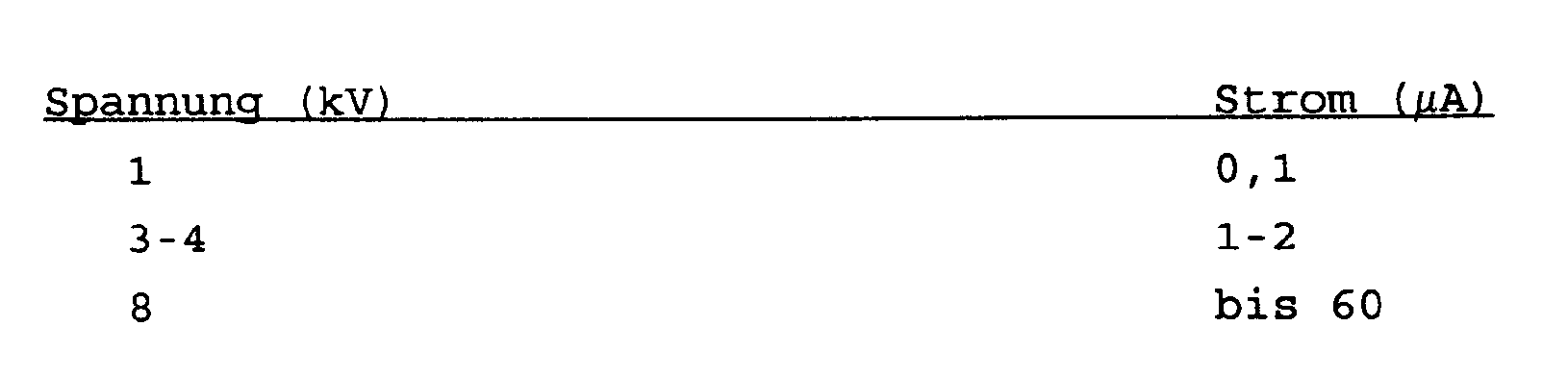
- Die Strom - Spannungscharakteristik soll nicht-linear sein mit einem steilen Anstieg der Kurve bei ca. 4 kV/ cm; Richtwerte:
- Im besonderen muß der Feldsteuerungsbelag als Bestandteil einer Garnitur die nachstehend aufgeführten elektrischen Prüfungen nach DIN 57 278/ VDE 0278 bestehen (z.B. für ein 20 kV - System):
- Nennstehwechselspannungsprüfung
(einminütige Stehspannung von 55 kV) - Gleichspannungsprüfung
(96 kV über 30 Minuten) - Nennstehstoßspannungsprüfung
(125 kV, beide Polaritäten je 10 Stöße) - Dauerwechselspannungsprüfung bei zyklischer Strombelastung
(126 Heizzyklen trocken) - Teilentladungsmessung
(teilentladungsfrei bei 24 kV ( ≦ 1 pC) - Langzeitprüfung
(Lastwechsel bei 30 kV) - So ergibt sich für vorliegende Erfindung die Aufgabe, ein Verfahren zur Herstellung eines Feldsteuerungsbelages in Mittelspannungsgarnituren zu schaffen, durch das eine einfache Beschichtung auf der Innenseite möglich wird, wobei dadurch ein ausfallfreies Langzeitverhalten erreicht und durch günstige Rohstoffkombination die elektrischen Anforderungen wie auch das Erweichungsverhalten, das Fließvermögen, die Klebfähigkeit und die Löslichkeit verbessert werden soll. Die gestellte Aufgabe wird nun nach einem Verfahren gemäß der Erfindung dadurch gelöst, daß das Polymermaterial aus einem zähflüssigen, stark klebrigen Ethylenpropylendienterpolymer (EPDM) in einem leicht unpolaren Lösungsmittel gelöst wird, wobei das mittlere Molekulargewicht,

- Die Auswahl der Rohstoffe zur Entwicklung eines Feldsteuerungsbelages gemäß der Erfindung und die erfindungsgemäße Kombination mit einem wärmeschrumpfenden Element zur Bildung einer feldsteuernden Mittelspannungsgarnitur erfordert eine sorgfältige Abstimmung. Dabei steht gemäß der Aufgabe der Erfindung im Vordergrund, daß die Rezeptur einfach und mit wenigen Komponenten zusammenzustellen sein muß, um u.a. auch eine sichere Reproduzierbarkeit in der Fertigung gewährleisten zu können.
- Als Hauptwirkstoff wird nun für den Feldsteuerungsbelag gemäß der Erfindung Siliciumcarbid verwendet, das keine magnetischen Eigenschaften besitzt und daher eine vergleichbar bessere Spannungsstabilität nach transienten Überspannungen aufweist als das bekannte Eisen (II, III) -oxid. Für die Funktion des Feldsteuerungsbelages ist erwartungsgemäß der Mengenanteil des Siliciumcarbids sowie dessen Korngröße entscheidend.
- Für die Polymermatrix des Feldsteuerungsbelags gemäß der Erfindung wird ein Rohstoff verwendet, der die folgenden Voraussetzungen erfüllt:
- Das Polymer muß in einem handelsüblichen, relativ tiefsiedenden Lösungsmittel bei Raumtemperatur vollständig gelöst werden.
- Das Polymer muß sehr große Füllstoffmengen aufnehmen können.
- Das hochgefüllte Polymer muß bei 90 - 100° C eine noch hinreichende Klebrigkeit entwickeln.
- Nach Abdunsten des Lösungsmittels aus der Beschichtung muß diese ausreichend flexibel sein und eine glatte Oberfläche ausbilden (keine Rißbildung infolge Sprödigkeit der trockenen Masse).
- Gemäß der Erfindung wird nun als Polymer in Form eines Harzes, das die vorstehend genannten Anforderungen erfüllt, ein zähflüssiges, stark klebriges Ethylenpropylendienterpolymer (EPDM) oder Ethylenpropylencopolymer (EPM) gewählt. Dieses Polymer kann leicht in unpolaren Lösungsmitteln wie zum Beispiel Petroleumbenzin (Siedebereich 40 - 60° C) oder anderen Kohlenwasserstoff - Lösemitteln bzw. in chlorierten Kohlenwasserstoffen wie 1.1.1 - Trichlorethan gelöst werden. Die in Betracht kommenden EP(D)M - Harze besitzen mittlere Molekulargewichte (
M v) von 1000 bis 15000, vorzugsweise 6000 bis 8000. Als Dienkomponente kann Dicyclopentadien (DCP), Ethylidennorbornen (EN) oder 1.4 - Hexadien auftreten. Der Dienanteil im Harz liegt zwischen 0 und 13 Gewicht %, vorzugsweise bei 4,5 bis 9,5 Gewicht %, während das Ethylen-Propylen-Verhältnis im EP-Anteil zwischen 40/60 und 75/25 Gewicht %, vorzugsweise innerhalb des Bereichs 43/57 bis 54/46 Gewicht %, liegt. Es stellte sich heraus, daß zur Erfüllung der elektrischen Anforderungen ein Siliciumcarbid-Anteil zwischen 60 und 90 Gewicht %, vorzugsweise 80 Gewicht %, erforderlich ist. Als Korngrößen des Sic eignen sich besonders F 400 bis F 320. - Ein Feldsteuerungsbelag gemäß der Erfindung besitzt beispielsweise im EP(D)M/Sic Verhältnis folgende Zusammensetzung:
- 40 - 10 Gew. %
- Trilene 66
- 60 - 90 Gew. %
- Siliciumcarbid "Carbogran® dunkel" der Firma Lonza-Werke GmbH, Waldshut mit Mikrokorngröße F 360 oder F 320
- Die Menge des Lösungsmittels, zum Beispiel 1.1.1-Trichlorethan, wird entsprechend der für die Beschichtung erwünschten Viskosität festgelegt (ca. 30000 mPa.s/ 23° C).
- Als Polymermatrix kommen neben reinem EP(D)M - Flüssigharz auch Mischungen desselben mit anderen Harzen und/oder Kautschuken in Frage, die mit Trilene verträglich und in den genannten Lösungsmitteln löslich sind. Geeignete Polymere sind zum Beispiel andere EP(D)M - Typen mit abweichendem Molekulargewicht, Polyisobutylene und Butylkautschuk, Acrylatharze bzw. -kautschuk, Polybutene, ataktisches Polypropylen, Epichlorhydrinkautschuk.
- Ebenso können zusätzliche Klebrigmacher wie zum Beispiel Kolophoniumester und dessen Derivate, Tallharze, Kohlenwasserstoffharze und Terpen-Phenol-Harze in die Polymermatrix eingemischt werden.
- Zusätzlich zu den genannten Komponenten kann der Feldsteuerungsbelag ein oder mehrere Additive zur Verbesserung der thermooxidativen Stabilität (Antioxidantien) enthalten wie zum Beispiel Irganox 1010 oder Irganox 1076.
- Der Feldsteuerungsbelag wird gemäß der Erfindung auf der Innenseite eines Schrumpfschlauches aufgebracht, wie es in zwei Figuren näher erläutert wird.
- Figur 1
- zeigt den Schrumpfschlauch vor der Schrumpfung,
- Figur
- 2 zeigt den Schrumpfschlauch nach dem Schrumpfen im Einsatz als Endverschluß bei Mittelspannungsanlagen.
- Die Figur 1 zeigt den Schrumpfschlauch 1 aus an sich bekanntem Schrumpfmaterial, auf dessen Innenseite zumindest im erforderlich wirksamen Bereich der Feldsteuerungsbelag 2 gemäß der Erfindung aufgebracht ist.
- Die Figur 2 zeigt einen Endverschluß 4 für Mittelspannungsanlagen, wobei der Schrumpfschlauch 1 mit dem innen liegenden Feldsteuerungsbelag 2 auf das Kabelendstück aufgeschrumpft ist. Im Eingangsbereich ist auf der Innenseite des Schrumpfschlauches 1 ein kriechstromfester Kleber 3, zum Beispiel ein handelsüblicher Klebstoff auf der Basis von Polyisobutylen, der mit geeigneten Füllstoffen kriechstromfest ausgerüstet ist, aufgebracht, durch den eine Abdichtung erfolgt.
Claims (10)
- Verfahren zur Herstellung eines Feldsteuerungsbelages (2) aus einem Polymermaterial und einem elektrisch leitfähigen Zusatz bei einem Endverschluß (4) für Mittelspannungen, dadurch gekennzeichnet,
daß das Polymermaterial aus einem zähflüssigen, stark klebrigen Ethylenpropylendienterpolymer (EPDM) in einem leicht unpolaren Lösungsmittel gelöst wird, wobei das mittlere Molekulargewicht,
- Verfahren nach Anspruch 1,
dadurch gekennzeichnet,
daß als Dienkomponente Dicyclopentadien (DVP) verwendet wird. - Verfahren nach Anspruch 1,
dadurch gekennzeichnet,
daß als Dienkomponente Ethylidennorbornen (EN) verwendet wird. - Verfahren nach Anspruch 1,
dadurch gekennzeichnet,
daß als Dienkomponente 1.4 - Hexadien verwendet wird. - Verfahren nach einem der vorhergehenden Ansprüche,
dadurch gekennzeichnet,
daß als Lösungsmittel Petroleumbenzin mit einem Siedebereich 40° - 60° C verwendet wird. - Verfahren nach einem der Ansprüche 1 bis 4,
dadurch gekennzeichnet,
daß als Lösungsmittel ein chlorierter Kohlenwasserstoff, vorzugsweise 1.1.1-Trichlorethan verwendet wird. - Verfahren nach einem der vorhergehenden Ansprüche,
dadurch gekennzeichnet,
daß die hergestellte Lösung auf eine Viskosität im Bereich von vorzugsweise 30 000 m Pa.s/23° gebracht wird. - Verfahren nach einem der vorhergehenden Ansprüche,
dadurch gekennzeichnet,
daß als Polymermaterial ein gesättigtes, niedermolekulares Ethylen-alpha-Olefinpolymerisat mit und ohne 5-Ethyliden-2-norbornen/Dicyclopentadien verwendet wird. - Verfahren nach einem der vorhergehenden Ansprüche,
dadurch gekennzeichnet,
daß die Lösung aus den folgenden Bestandteilen zusammengemischt wird:21,1 Gewichts-% gesättigtes, niedermolekulares Ethylen-alpha-Olefinpolymerisat mit und ohne 5-Ethyliden-2- norbornen/ Dicyclopentadien49,2 Gewichts-% Siliciumcarbid29,7 Gewichts-% Lösungsmittel, vorzugsweise 1.1.1.-Trichlorethan. - Verfahren nach einem der vorhergehenden Ansprüche,
dadurch gekennzeichnet,
daß die Innenfläche der nicht beschichteten Bereiche des Schrumpfschlauches (1) mit einem Kleber, vorzugsweise einem kriechstromfesten Schmelzkleber, beschichtet wird.
Applications Claiming Priority (2)
| Application Number | Priority Date | Filing Date | Title |
|---|---|---|---|
| DE4000455 | 1990-01-09 | ||
| DE4000455 | 1990-01-09 |
Publications (3)
| Publication Number | Publication Date |
|---|---|
| EP0436821A2 EP0436821A2 (de) | 1991-07-17 |
| EP0436821A3 EP0436821A3 (en) | 1992-01-29 |
| EP0436821B1 true EP0436821B1 (de) | 1995-05-31 |
Family
ID=6397788
Family Applications (1)
| Application Number | Title | Priority Date | Filing Date |
|---|---|---|---|
| EP90122681A Expired - Lifetime EP0436821B1 (de) | 1990-01-09 | 1990-11-27 | Verfahren zur Herstellung eines Feldsteuerungsbelages für Mittelspannungsgarnituren |
Country Status (6)
| Country | Link |
|---|---|
| US (1) | US5524335A (de) |
| EP (1) | EP0436821B1 (de) |
| JP (1) | JP2986555B2 (de) |
| AT (1) | ATE123362T1 (de) |
| DE (1) | DE59009182D1 (de) |
| ES (1) | ES2072351T3 (de) |
Families Citing this family (2)
| Publication number | Priority date | Publication date | Assignee | Title |
|---|---|---|---|---|
| DK0681010T3 (da) * | 1994-05-02 | 2000-01-17 | Rxs Schrumpftech Garnituren | Fremgangsmåde til fremstilling af en feltstyringsbelægning for middelspændingsgarniturer |
| JP3340112B2 (ja) * | 2000-06-02 | 2002-11-05 | 北川工業株式会社 | 熱伝導材及びその製造方法 |
Family Cites Families (29)
| Publication number | Priority date | Publication date | Assignee | Title |
|---|---|---|---|---|
| US3210460A (en) * | 1963-07-15 | 1965-10-05 | Westinghouse Electric Corp | Terminating means for shielded electrical conductors |
| US3573210A (en) * | 1966-12-08 | 1971-03-30 | Furukawa Electric Co Ltd | Electric insulating composition containing an organic semiconducting material |
| US3576387A (en) * | 1970-03-19 | 1971-04-27 | Chomerics Inc | Heat shrinkable electromagnetic shield for electrical conductors |
| US3631519A (en) * | 1970-12-21 | 1971-12-28 | Gen Electric | Stress graded cable termination |
| GB1433129A (en) * | 1972-09-01 | 1976-04-22 | Raychem Ltd | Materials having non-linear resistance characteristics |
| US3816347A (en) * | 1972-11-02 | 1974-06-11 | Du Pont | Semiconductive elastomeric composition of chlorinated or chlorosulfonated polyethylene,ethylene polymer and conductive carbon black |
| US3963647A (en) * | 1974-08-22 | 1976-06-15 | E. I. Du Pont De Memours And Company | Electrostatically paintable injection moldable blend of propylene polymer, ethylene/higher α-olefin copolymer rubber and carbon black |
| GB1526397A (en) * | 1974-10-08 | 1978-09-27 | Raychem Ltd | Heat-recoverable article suitable for high voltage use |
| US4187389A (en) * | 1975-04-11 | 1980-02-05 | Sola Basic Industries, Inc. | Shielded electrical conductor terminations and methods of making same |
| GB1534003A (en) * | 1975-04-11 | 1978-11-29 | Sola Basic Ind Inc | Electrical stress-relieving elastomeric material devices made therewith and method of making shielded electrical conductor terminations |
| US4071652A (en) * | 1976-03-29 | 1978-01-31 | Minnesota Mining And Manufacturing Company | Thermally conductive electrical tape |
| GB1604612A (en) * | 1976-10-29 | 1981-12-09 | Raychem Ltd | Epihalohydrin polymer compositions |
| US4275261A (en) * | 1978-01-11 | 1981-06-23 | Trefimetaux | End piece for high voltage cables |
| US4363842A (en) * | 1981-03-02 | 1982-12-14 | Minnesota Mining And Manufacturing Company | Elastomeric pre-stretched tubes for providing electrical stress control |
| US4487994A (en) * | 1981-11-09 | 1984-12-11 | Cable Technology Laboratories, Ltd. | Electrical cable joint structure and method of manufacture |
| JPS58157318A (ja) * | 1982-03-10 | 1983-09-19 | 古河電気工業株式会社 | ゴム・プラスチツク絶縁ケ−ブルの絶縁接続部 |
| GB8303462D0 (en) * | 1983-02-08 | 1983-03-16 | Raychem Gmbh | Electrical stress control |
| US4551915A (en) * | 1983-04-06 | 1985-11-12 | Raychem Corporation | Method for terminating a high voltage cable |
| FR2547451B1 (fr) * | 1983-06-13 | 1986-02-28 | Electricite De France | Materiau composite a resistance electrique non lineaire, notamment pour la repartition du potentiel dans les extremites de cables |
| GB2152060B (en) * | 1983-12-02 | 1987-05-13 | Osaka Soda Co Ltd | Electrically conductive adhesive composition |
| US4667401A (en) * | 1985-11-26 | 1987-05-26 | Clements James R | Method of making an electronic device using an uniaxial conductive adhesive |
| US4935467A (en) * | 1987-06-04 | 1990-06-19 | Raychem Corporation | Polymeric blends |
| US5028354A (en) * | 1987-10-05 | 1991-07-02 | Regents Of The University Of California | Conductive articles of intractable polymers method for making |
| US4929391A (en) * | 1988-07-20 | 1990-05-29 | Dow Corning Corporation | Electrically conductive silicon compositions |
| JP5111129B2 (ja) | 2008-01-22 | 2012-12-26 | キヤノン株式会社 | 情報処理装置、情報処理システム、情報処理方法、及び、プログラム |
| JP5138070B2 (ja) | 2011-05-09 | 2013-02-06 | 京楽産業.株式会社 | 遊技機 |
| JP5842922B2 (ja) | 2011-09-30 | 2016-01-13 | コニカミノルタ株式会社 | 発光装置及び塗布液 |
| JP6123734B2 (ja) | 2014-05-29 | 2017-05-10 | Jfeスチール株式会社 | 鋼管杭向け低降伏比高強度電縫鋼管およびその製造方法 |
| JP6123735B2 (ja) | 2014-05-30 | 2017-05-10 | Jfeスチール株式会社 | 王冠用鋼板、その製造方法および王冠 |
-
1990
- 1990-11-27 ES ES90122681T patent/ES2072351T3/es not_active Expired - Lifetime
- 1990-11-27 DE DE59009182T patent/DE59009182D1/de not_active Expired - Fee Related
- 1990-11-27 AT AT90122681T patent/ATE123362T1/de not_active IP Right Cessation
- 1990-11-27 EP EP90122681A patent/EP0436821B1/de not_active Expired - Lifetime
-
1991
- 1991-01-07 JP JP3000133A patent/JP2986555B2/ja not_active Expired - Fee Related
-
1994
- 1994-04-25 US US08/232,330 patent/US5524335A/en not_active Expired - Fee Related
Also Published As
| Publication number | Publication date |
|---|---|
| ATE123362T1 (de) | 1995-06-15 |
| DE59009182D1 (de) | 1995-07-06 |
| JP2986555B2 (ja) | 1999-12-06 |
| ES2072351T3 (es) | 1995-07-16 |
| US5524335A (en) | 1996-06-11 |
| EP0436821A2 (de) | 1991-07-17 |
| JPH04271223A (ja) | 1992-09-28 |
| EP0436821A3 (en) | 1992-01-29 |
Similar Documents
| Publication | Publication Date | Title |
|---|---|---|
| DE69605808T2 (de) | Epihalohydrinwerkstoff zur verminderung elektrischer beanspruchung | |
| DE2415304C3 (de) | Druckempfindlicher, elektrisch isolierender Klebestreifen | |
| DE69610400T2 (de) | Universeller Kabeladapter, mit Hilfe des Adapters hergestellte Kabelverbindung sowie Verfahren zur Herstellung derselben | |
| DE60107864T2 (de) | Kabel mit einem wiederverwertbaren kabelmantel | |
| DE69232192T2 (de) | Wasserdichte elektrische Verbinder | |
| DE60104029T2 (de) | Hoch und Höchstspannungsgleichstromenergiekabel | |
| DE2405012A1 (de) | Abziehbarer verbundstoff aus polymeren materialien | |
| DE2545084A1 (de) | Waermerueckstellfaehiger gegenstand | |
| DE2737487A1 (de) | Mit einem vernetzten polyolefin elektrisch isoliertes hochspannungs- kabel | |
| US6015629A (en) | Stress control for termination of a high voltage cable | |
| DE2748371C2 (de) | ||
| WO2010018108A1 (de) | Haftklebemasse | |
| DE69912868T2 (de) | Elektrisches Kabel mit selbstheilendem Kabelschutz | |
| DE2051268A1 (de) | Isoliertes elektrisches Kabel | |
| DE69917313T2 (de) | Elektrokabel und herstellungsverfahren | |
| DE69031123T2 (de) | Elektrisch leitfähige polymerzusammensetzung | |
| DE69837723T2 (de) | Zusammensetzung für einen elektrische leitung | |
| DE2714119A1 (de) | Waermeleitendes elektroband | |
| DE69503131T3 (de) | Zylindrische, radial schrumpfbare muffe fuer elektrisches kabel und ihre zusammensetzung | |
| EP0354521A2 (de) | Abrutschfester Schmelzkleber,insbesondere für Beschichtungen bei Schrumpfprodukten | |
| DE69817386T2 (de) | Elektrisches kabel und ein verfahren sowie zusammensetzung zu dessen herstellung | |
| DE2456330A1 (de) | Aushaertbarer isolierstoff fuer elektrische isolationszwecke | |
| DE2723488A1 (de) | Elektrisches kabel mit kunststoffisolierung und aeusserer leitschicht | |
| EP0436821A2 (de) | Verfahren zur Herstellung eines Feldsteuerungsbelages für Mittelspannungsgarnituren | |
| DE7610884U1 (de) | Elektrisches Stromleitungskabel mit in Längsrichtung wirkender Feuchtigkeitssperre |
Legal Events
| Date | Code | Title | Description |
|---|---|---|---|
| PUAI | Public reference made under article 153(3) epc to a published international application that has entered the european phase |
Free format text: ORIGINAL CODE: 0009012 |
|
| 17P | Request for examination filed |
Effective date: 19901220 |
|
| AK | Designated contracting states |
Kind code of ref document: A2 Designated state(s): AT BE CH DE ES FR GB GR IT LI NL SE |
|
| PUAL | Search report despatched |
Free format text: ORIGINAL CODE: 0009013 |
|
| AK | Designated contracting states |
Kind code of ref document: A3 Designated state(s): AT BE CH DE ES FR GB GR IT LI NL SE |
|
| 17Q | First examination report despatched |
Effective date: 19940215 |
|
| GRAA | (expected) grant |
Free format text: ORIGINAL CODE: 0009210 |
|
| AK | Designated contracting states |
Kind code of ref document: B1 Designated state(s): AT BE CH DE ES FR GB GR IT LI NL SE |
|
| REF | Corresponds to: |
Ref document number: 123362 Country of ref document: AT Date of ref document: 19950615 Kind code of ref document: T |
|
| REF | Corresponds to: |
Ref document number: 59009182 Country of ref document: DE Date of ref document: 19950706 |
|
| REG | Reference to a national code |
Ref country code: ES Ref legal event code: FG2A Ref document number: 2072351 Country of ref document: ES Kind code of ref document: T3 |
|
| ITF | It: translation for a ep patent filed | ||
| REG | Reference to a national code |
Ref country code: GR Ref legal event code: FG4A Free format text: 3016335 |
|
| GBT | Gb: translation of ep patent filed (gb section 77(6)(a)/1977) |
Effective date: 19950814 |
|
| ET | Fr: translation filed | ||
| PLBE | No opposition filed within time limit |
Free format text: ORIGINAL CODE: 0009261 |
|
| STAA | Information on the status of an ep patent application or granted ep patent |
Free format text: STATUS: NO OPPOSITION FILED WITHIN TIME LIMIT |
|
| 26N | No opposition filed | ||
| PGFP | Annual fee paid to national office [announced via postgrant information from national office to epo] |
Ref country code: SE Payment date: 20011101 Year of fee payment: 12 |
|
| PGFP | Annual fee paid to national office [announced via postgrant information from national office to epo] |
Ref country code: AT Payment date: 20011105 Year of fee payment: 12 Ref country code: CH Payment date: 20011105 Year of fee payment: 12 |
|
| PGFP | Annual fee paid to national office [announced via postgrant information from national office to epo] |
Ref country code: GR Payment date: 20011121 Year of fee payment: 12 |
|
| PGFP | Annual fee paid to national office [announced via postgrant information from national office to epo] |
Ref country code: ES Payment date: 20011207 Year of fee payment: 12 |
|
| REG | Reference to a national code |
Ref country code: GB Ref legal event code: IF02 |
|
| PG25 | Lapsed in a contracting state [announced via postgrant information from national office to epo] |
Ref country code: AT Free format text: LAPSE BECAUSE OF NON-PAYMENT OF DUE FEES Effective date: 20021127 |
|
| PG25 | Lapsed in a contracting state [announced via postgrant information from national office to epo] |
Ref country code: SE Free format text: LAPSE BECAUSE OF NON-PAYMENT OF DUE FEES Effective date: 20021128 Ref country code: ES Free format text: LAPSE BECAUSE OF NON-PAYMENT OF DUE FEES Effective date: 20021128 |
|
| PG25 | Lapsed in a contracting state [announced via postgrant information from national office to epo] |
Ref country code: CH Free format text: LAPSE BECAUSE OF NON-PAYMENT OF DUE FEES Effective date: 20021130 Ref country code: LI Free format text: LAPSE BECAUSE OF NON-PAYMENT OF DUE FEES Effective date: 20021130 |
|
| BECA | Be: change of holder's address |
Owner name: *CCS TECHNOLOGY INC.103 FOULK ROAD, WILMINGTON, DE Effective date: 20030402 |
|
| BECH | Be: change of holder |
Owner name: *CCS TECHNOLOGY INC. Effective date: 20030402 |
|
| BECN | Be: change of holder's name |
Owner name: *CCS TECHNOLOGY INC. Effective date: 20030402 |
|
| PG25 | Lapsed in a contracting state [announced via postgrant information from national office to epo] |
Ref country code: GR Free format text: LAPSE BECAUSE OF NON-PAYMENT OF DUE FEES Effective date: 20030609 |
|
| EUG | Se: european patent has lapsed | ||
| REG | Reference to a national code |
Ref country code: CH Ref legal event code: PL |
|
| REG | Reference to a national code |
Ref country code: GB Ref legal event code: 732E |
|
| REG | Reference to a national code |
Ref country code: FR Ref legal event code: TP Ref country code: FR Ref legal event code: CA Ref country code: FR Ref legal event code: CD |
|
| NLS | Nl: assignments of ep-patents |
Owner name: CCS TECHNOLOGY, INC. |
|
| NLT1 | Nl: modifications of names registered in virtue of documents presented to the patent office pursuant to art. 16 a, paragraph 1 |
Owner name: RXS KABELGARNITUREN GESELLSCHAFT MIT BESCHRAENKTER Owner name: RXS GESELLSCHAFT FUER VERMOEGENSVERWALTUNG MBH |
|
| REG | Reference to a national code |
Ref country code: ES Ref legal event code: FD2A Effective date: 20031213 |
|
| PG25 | Lapsed in a contracting state [announced via postgrant information from national office to epo] |
Ref country code: IT Free format text: LAPSE BECAUSE OF NON-PAYMENT OF DUE FEES;WARNING: LAPSES OF ITALIAN PATENTS WITH EFFECTIVE DATE BEFORE 2007 MAY HAVE OCCURRED AT ANY TIME BEFORE 2007. THE CORRECT EFFECTIVE DATE MAY BE DIFFERENT FROM THE ONE RECORDED. Effective date: 20051127 |
|
| PGFP | Annual fee paid to national office [announced via postgrant information from national office to epo] |
Ref country code: DE Payment date: 20081127 Year of fee payment: 19 Ref country code: NL Payment date: 20081130 Year of fee payment: 19 |
|
| PGFP | Annual fee paid to national office [announced via postgrant information from national office to epo] |
Ref country code: BE Payment date: 20081128 Year of fee payment: 19 |
|
| PGFP | Annual fee paid to national office [announced via postgrant information from national office to epo] |
Ref country code: FR Payment date: 20081126 Year of fee payment: 19 |
|
| PGFP | Annual fee paid to national office [announced via postgrant information from national office to epo] |
Ref country code: GB Payment date: 20081127 Year of fee payment: 19 |
|
| BERE | Be: lapsed |
Owner name: *CCS TECHNOLOGY INC. Effective date: 20091130 |
|
| REG | Reference to a national code |
Ref country code: NL Ref legal event code: V1 Effective date: 20100601 |
|
| GBPC | Gb: european patent ceased through non-payment of renewal fee |
Effective date: 20091127 |
|
| REG | Reference to a national code |
Ref country code: FR Ref legal event code: ST Effective date: 20100730 |
|
| PG25 | Lapsed in a contracting state [announced via postgrant information from national office to epo] |
Ref country code: NL Free format text: LAPSE BECAUSE OF NON-PAYMENT OF DUE FEES Effective date: 20100601 Ref country code: FR Free format text: LAPSE BECAUSE OF NON-PAYMENT OF DUE FEES Effective date: 20091130 Ref country code: BE Free format text: LAPSE BECAUSE OF NON-PAYMENT OF DUE FEES Effective date: 20091130 |
|
| PG25 | Lapsed in a contracting state [announced via postgrant information from national office to epo] |
Ref country code: DE Free format text: LAPSE BECAUSE OF NON-PAYMENT OF DUE FEES Effective date: 20100601 |
|
| PG25 | Lapsed in a contracting state [announced via postgrant information from national office to epo] |
Ref country code: GB Free format text: LAPSE BECAUSE OF NON-PAYMENT OF DUE FEES Effective date: 20091127 |