EP0436116A2 - Kernbrennstabbündelabstandshalter mit ringfedererhöhter Flexibilität - Google Patents
Kernbrennstabbündelabstandshalter mit ringfedererhöhter Flexibilität Download PDFInfo
- Publication number
- EP0436116A2 EP0436116A2 EP90122596A EP90122596A EP0436116A2 EP 0436116 A2 EP0436116 A2 EP 0436116A2 EP 90122596 A EP90122596 A EP 90122596A EP 90122596 A EP90122596 A EP 90122596A EP 0436116 A2 EP0436116 A2 EP 0436116A2
- Authority
- EP
- European Patent Office
- Prior art keywords
- spring
- fuel
- shaped
- rod
- loop
- Prior art date
- Legal status (The legal status is an assumption and is not a legal conclusion. Google has not performed a legal analysis and makes no representation as to the accuracy of the status listed.)
- Granted
Links
Images


Classifications
-
- G—PHYSICS
- G21—NUCLEAR PHYSICS; NUCLEAR ENGINEERING
- G21C—NUCLEAR REACTORS
- G21C3/00—Reactor fuel elements and their assemblies; Selection of substances for use as reactor fuel elements
- G21C3/30—Assemblies of a number of fuel elements in the form of a rigid unit
- G21C3/32—Bundles of parallel pin-, rod-, or tube-shaped fuel elements
- G21C3/33—Supporting or hanging of elements in the bundle; Means forming part of the bundle for inserting it into, or removing it from, the core; Means for coupling adjacent bundles
-
- G—PHYSICS
- G21—NUCLEAR PHYSICS; NUCLEAR ENGINEERING
- G21C—NUCLEAR REACTORS
- G21C3/00—Reactor fuel elements and their assemblies; Selection of substances for use as reactor fuel elements
- G21C3/30—Assemblies of a number of fuel elements in the form of a rigid unit
- G21C3/32—Bundles of parallel pin-, rod-, or tube-shaped fuel elements
- G21C3/34—Spacer grids
- G21C3/344—Spacer grids formed of assembled tubular elements
-
- G—PHYSICS
- G21—NUCLEAR PHYSICS; NUCLEAR ENGINEERING
- G21C—NUCLEAR REACTORS
- G21C3/00—Reactor fuel elements and their assemblies; Selection of substances for use as reactor fuel elements
- G21C3/30—Assemblies of a number of fuel elements in the form of a rigid unit
- G21C3/32—Bundles of parallel pin-, rod-, or tube-shaped fuel elements
- G21C3/34—Spacer grids
- G21C3/356—Spacer grids being provided with fuel element supporting members
- G21C3/3566—Supporting members formed only of elements fixed on the strips
-
- Y—GENERAL TAGGING OF NEW TECHNOLOGICAL DEVELOPMENTS; GENERAL TAGGING OF CROSS-SECTIONAL TECHNOLOGIES SPANNING OVER SEVERAL SECTIONS OF THE IPC; TECHNICAL SUBJECTS COVERED BY FORMER USPC CROSS-REFERENCE ART COLLECTIONS [XRACs] AND DIGESTS
- Y02—TECHNOLOGIES OR APPLICATIONS FOR MITIGATION OR ADAPTATION AGAINST CLIMATE CHANGE
- Y02E—REDUCTION OF GREENHOUSE GAS [GHG] EMISSIONS, RELATED TO ENERGY GENERATION, TRANSMISSION OR DISTRIBUTION
- Y02E30/00—Energy generation of nuclear origin
- Y02E30/30—Nuclear fission reactors
Definitions
- the present invention relates to a spacer usable for positioning fuel rods and water rods in a nuclear fuel assembly and springs therefor, and, in particular, to springs that occupy reduced space in such spacers.
- nuclear fuel is provided in elongated rods.
- the nuclear fuel is typically in the form of uranium oxide and/or plutonium oxide pellets enclosed in zircaloy tubes.
- a number of such fuel rods are grouped together in an open-ended tubular flow channel.
- the flow channel with the fuel rods positioned therein is referred to as a "fuel assembly" or "bundle.”
- a plurality of fuel assemblies are removably positioned in the reactor core in a matrix.
- the reactor core formed in this manner is capable of self-sustained fission reaction.
- the core is submerged in a fluid, such as light water, which serves both as a coolant and as a neutron moderator.
- the fuel rods in a fuel assembly are supported between upper and lower tie plates.
- the fuel rods are typically arrayed in parallel side by side vertical upstanding relation.
- the fluid coolant flows past the fuel rods in the intersticies between the vertical and parallel fuel rods. To provide proper coolant flow and preserve integrity of the fuel rods, it is important to maintain the rods in a preferred spaced relationship and to restrain them from bowing and vibrating during reactor operation.
- a plurality of fuel rod spacers spaced along the length of the fuel assembly are provided for this purpose.
- One type of spacer includes a plurality of generally cylindrical ferrule elements.
- An example of a spacer usable in a fuel assembly is that shown in U.S. Patent 4,508,679, issued April 2, 1989, to Matzner, et al.
- one method of positioning a fuel rod within the ferrule elements of a spacer is to provide a spring member for biasing the fuel rod against rigid stops in the ferrules.
- the spring depicted in U.S. Patent 4,508,679 is in the form of a continuous loop of generally elliptical shape. The springs are positioned in the volume of the spacer area between adjacent fuel rods.
- Modern fuel bundle design typically includes fuel rods being arrayed in a square sectioned fuel bundle.
- the arrays originally where in a 7 x 7 matrix. This left relatively large spaces between the fuel rods. Accordingly, the problem of placing springs between the rod to maintain the rods in vertical upstanding relation presented a generally simple mechanical design problem.
- Modern fuel bundles are being designed with 9 x 9 matricies of fuel rods to have a reduced rod-to-rod spacing, such as about 0.12-0.14 inches (about 3 to about 3.5 mm). This reduction in fuel rod interstitial spacing has had severe constraints on the spring design.
- the springs although necessary for positioning the rods, can have certain undesirable effects. These undesirable effects include absorption of neutrons and interference with the coolant circulation. Materials from which the springs are typically formed absorb 20-100 times the number of neutrons absorbed by the spacer material. Accordingly, there is a high motive to maintain a minimum of spring material within the fuel bundle.
- a spring system is provided for bracing side by side fuel rods in dense (9 x 9) arrays.
- the spring system is incorporated to the several spacers, typically 6, 7 or 8 positioned at vertically distributed intervals between the upper and lower tie plates in a square sectioned fuel bundle.
- the spacers and springs disclosed maintain a substantially uniform spacing between the vertically upstanding fuel rods and water rods contained with the fuel bundle.
- a loop spring is provided as the main fuel rod biasing unit. Like the prior art, the loop spring surrounds portions of the spacer and is thus held in a generally vertically disposed elongate loop by the spacer.
- Each loop spring acts on typically a pair of fuel rods, one rod being on each side of the spring.
- Each fuel rod is confined within its own discrete ferrule at the spacer and is spring biased by the spring against paired protuberances.
- Each loop spring includes upper and lower C-shaped end portions for retaining the spring to the spacer. In between each upper and lower C-shaped end portions there are formed two spring legs. The spring legs begin at the ends of each "C" and flare with gradual reversing curvature to substantially linear spring leg portions.
- Each spring leg includes in the center of the leg a convex and outwardly disposed arched shaped rod contacting portion for spring biased contact with the fuel rods on either side of the spring. Unlike the prior art, two inwardly disposed U-shaped bends are incorporated in each spring leg immediately on either side of the outwardly disposed arched shaped rod contacting portion.
- the disclosed 9 x 9 matrix fuel bundle has the seven middle lattice positions occupied by two relatively large and circularly sectioned water rods. Seven central ferrules are removed to provide space for the water rods. Two ferrules adjacent to the water rods are not paired with another ferrule, so that the spring in each of these ferrules acts on only one fuel rod. A special method for mounting these springs is required.
- a water rod spacer place is disclosed.
- This plate has two functions. First, it provides the required mounting for the disclosed loop springs in the locations where the spring bears on one rod only. Second, the water rod spacer plate provides stops for the water rods.
- the water rod spacer plate has a U-shaped central region for bearing against the two water rods at their adjoining exterior surfaces. One lower portion of the "U” bears against one water rod; the other lower portion of the "U” bears against the other water rod. These contact regions provide stops for the water rods. A spring mounted on a separate plate biases each water rod toward these stops.
- the water rod spacer plate has a wing at each end of the U-shaped central region. Each of these wings is shaped to provide mounting means for the springs which bear against only one fuel rod.
- At least one spring must be provided with a fuel rod on one side only.
- This spring is conveniently mounted on a disclosed interlock between a tab protruding from the specially constructed fuel rod ferrule and a mating tab on the "U" sectioned water rod spacer member. Accordingly, required bias is supplied against all spaced apart vertical fuel rods and water rods of the dense 9 x 9 matrix fuel bundle.
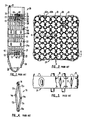
- the spring-and-spacer assembly of the present invention is provided for use in connection with a fuel assembly, such as that depicted in Fig. 1.
- the fuel assembly 20 includes a plurality of fuel elements or rods 21, supported between an upper tie plate 22 and a lower tie plate 23.
- the fuel rods 21 pass through a plurality of fuel rod spacers 24a, 24b, which provide intermediate support to retain the elongated rods 21 in spaced relation and to restrain them from lateral vibration.
- seven spacers are longitudinally evenly spaced along the fuel assembly.
- the fuel bundle is in the order of eleven feet in length.
- the matrix of fuel rods and water rods is in the order of 5 inches x 5 inches.
- Each of the fuel rods 21 is formed of an elongated tubular cladding material containing fissile fuel and other materials, such as burnable nuclear poison, inert material, or the like.
- the fuel and other materials are sealed in the tube by upper and lower end plugs 26, 27.
- the lower end plugs 27 are registered and positioned in cavities 29 formed in the lower tie plate 23.
- the upper end plugs 26 fit into cavities 31 in the upper tie plate 22.
- Some of the fuel rods 21 may be provided with threaded lower and upper end plug extensions 27', 28' to receive retaining nuts 32. These fuel rods are known as “tie rods.” In this manner, the upper and lower tie plates and fuel rods are formed into a unitary structure.
- the fuel rod assembly includes a channel 33 of substantially square cross section sized to form a sliding fit over the upper and lower tie plates 22 and 23 and the spacers 24, so that the channel 33 may readily be remounted and removed.
- the channel 33 is fastened to a post 36 on the upper tie plate 22 by means of a bolt 37 passing through a tab 34.
- the lower tie plate 23 includes a nose piece 38 adapted to support the fuel assembly 20 in a socket in a core support plate (not shown) in the reactor pressure vessel. The end of the nose piece is formed with openings 39 to receive the pressurized coolant so that it can flow upwardly among the fuel rods.
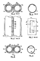
- One or more of the fuel rods 21 may be replaced by a moderator tube or water rod 41 which contains water, a neutron moderator.
- the moderator tube 41 may be apertured, as shown at 42 and 43, and the upper and lower end plugs may be formed with passages 44, 46 to permit flow of water moderator therethrough.
- a prior art spacer 24, as depicted in Figs. 2 and 3, is made up of a plurality of substantially cylindrical ferrules 51 joined to one another, for example by welding, at the upper and lower edges of abutting portions of adjacent ferrules.
- Each of the ferrules 51 provides a space for a fuel rod 21 or moderator tube 41.
- each of the ferrules 51 is formed of a short section of tubing having circular cross section.
- a peripheral band 56 surrounds and supports the plurality of ferrules 51.
- Two stops 62a, 62b are provided in each ferrule.
- the stops 62a, 62b are formed integrally with the ferrule 51 as laterally spaced pairs of arched portions of the ferrule walls near the upper and lower edges of the ferrule.
- each pair of ferrules 51 shares a continuous loop spring 70.
- the continuous loop spring 70 used in previous devices, includes first, second, third, and fourth legs 72a, 72b, 72c, 72d joined by mid-positioned ridges or convex arcuate spring contacting portions 74a, 74b and end-positioned arches or C-shaped portions 76a, 76b.
- the springs 70 depicted in Fig. 3, are in their substantially unstressed or unflexed condition.
- the springs in the flexed or stressed condition are depicted in Figs. 5 and 6.
- the springs 70 occupy a region between two adjacent fuel rods.
- the rod-to-rod spacing 78 was approximately 0.16 inches (about 4 mm).
- the previous spring 70 contacted the fuel rods 82a, 82b at the ridge portion 74a, 74b, and provided a force tending to position the fuel rods 82a, 82b against the stops 62a, 62b of each ferrule.
- Each ferrule 51 was provided with a C-shaped slot 84, defining a tab 86.
- the spring 70 was inserted into the slot 84 and positioned over the tab 86.
- An adjacent ferrule was fitted to the initial ferrule, with the C-shaped slot of the second ferrule oriented with the tab 86 pointing in the opposite direction from the tab of the first ferrule.
- the tabs 86 of the first and second ferrules overlapped each other. The spring was then captured between the two ferrules, and formed a loop around the overlapped tabs 86.
- the spring which is used in a spring-and-spacer assembly must provide the required amount of force, preferably about 2.5 pounds (about 1 kg), but must also have sufficient flexibility to tolerate deflection beyond that normally needed for positioning the fuel rod without substantial permanent deformation. Deflection of the spring beyond that normally needed for positioning the fuel rod can occur, for example, during shipping or assembly, particularly if the fuel rod 82 is encased, during assembly, in a protective plastic sheath (not shown). As shown in Fig.
- the previous loop spring 70 could deflect only a limited distance before the interior surface of the spring 70 would strike the tab 86 of the ferrule. This limitation places close tolerances on the configuration of the spring 70, particularly when a smaller rod-to-rod spacing 78, such as about 0.12 to 0.14 inches (about 3 to 3.5 mm) is desired.
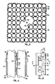
- Fig. 9 depicts a spacer and the associated springs according to the present invention.
- the springs 92a and 92b are arranged such that a single spring 92a loads the fuel rods positioned in two adjacent ferrules 94a, 94b.
- the overall length 95 (Fig. 20) of the spring is less than the length 97 of the ferrules 94a, 94b.
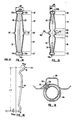
- Figs. 10 and 11 depict a portion of a spacer and the associated springs according to the present invention.
- a spring 92a is formed of a metallic ribbon having a width 96 (Fig. 20) and a thickness 98 (Fig. 16).
- the spring can be formed of a number of materials having suitable strength, corrosion resistance, and resilience characteristics.
- the spring is formed of a nickel alloy, such as Inconel ⁇ , available from Huntington Alloy Products Division, International Nickel Co., Inc., Huntington, W. VA.
- the width 96 is about 0.1 to about 0.15 inches (about 2.5 to 3.8 mm)
- the thickness 98 is about 0.01 to 0.015 inches (about 0.25 to 0.38 mm).
- the ribbon is formed into a continuous loop, i.e. , a shape with a cross section topologically equivalent to an annulus.
- the spring has at least two planes of symmetry, a longitudinal mid-plane 102 and a lateral mid-plane 104 (Fig. 15).
- the spring has four congruent sectors, the lower-right sector being depicted in Fig. 16.
- the longitudinal extent of the spring can be considered as having seven sections, as shown in Fig. 15.
- a ridge or arch-shaped rod-contacting portion 106 is formed in each leg, centered about the lateral symmetry plane 104 at the mid-span of each leg.
- Disposed on either side of the arch section 106 are U-shaped bend portions 108, 112 extending in a direction generally toward the longitudinal mid-plane 102.
- Upper and lower leg portions 114, 116 are positioned adjacent the bend portions 108, 112, respectively.
- C-shaped end portions 118, 122 are adjacent the leg portions 114, 116.
- U-shaped bend portions 108, 112 constitute the departure from the prior art which makes the disclosed spring design possible. Specifically, U-shaped bend portions 108, 112 are formed adjacent to each of the two arch-shaped rod-contacting regions 106. Viewed from the exterior of the spring, the bend portions 108, 112 are concave, i.e. , they extend toward the interior of the loop spring. The bend portions 108, 112 are on the loop interior side of the planes defined by the adjacent, substantially planar upper and lower leg portions 114, 116.
- a first region where the bending stress is high is the convex and outwardly disposed arch shaped rod contacting portion of the spring 106. This member has effective maximum compression forces acting on the outside of the spring member at this juncture and maximum tension forces acting on the inside of the spring member.
- a second region where the bending stress is high (and oppositely disposed) is in the upper and lower C-shaped members 118, 122. In these members the bending stress is the opposite with maximum tensile forces on the outside and maximum tension forces on the inside.
- the shape of the spring of the present invention 15 can be contrasted with that of the previous devices depicted in Fig. 14.
- the width 124' of the previous design was greater than the end portion width 124 of the present design.
- the previous design, shown in Fig. 14, did not include U-shaped portions 108, 112 adjacent to the rod-contacting region, so that the previous design spring had a rod-contacting portion 106' which was immediately adjacent to the substantially planar upper and lower leg portions 114', 116'.
- the spring 92' encircled and accommodated a double thickness of the tabs 126, 128 formed in adjacent ferrules, since these were positioned in an overlapping configuration.
- the tabs 126, 128 of the previous design, depicted in Fig. 14, were longitudinally continuous.
- both the previous spring design, depicted in Fig. 14, and the present spring design, depicted in Fig. 15, are loaded by forces 136', 136, respectively, where the springs 92', 92 contact the fuel rods.
- some flexibility is provided by the arch-shaped projections in the rod-contacting region 106' and by the projections 138a, 138b, 138c, 138d, and horizontal portions 142a, 142b of the end regions 118', 122'.
- the bend portions 108, 112 provide increased flexibility, as compared to the prior art spring.
- the bend regions 108, 112 provide a more desirable stress distribution.
- the largest stresses on the spring occur near the spring contact portion 106' and in the center of the end portions 142a, 142b.
- Finite element computer analysis of the previous spring designs of Fig. 14 shows that the stress at mid-span 106' is greater than the stress at the ends 142a, 142b.
- the ends 142a, 142b have greater local flexibility than the mid-span region 106'. This greater flexibility at the ends reduces the stress near the ends 142a, 142b, and increases the relative stress at mid-span 106'.
- Equal stress gives a more efficient structure. It is desired to get maximum deflection at a prescribed load; local yield of material limits the load. Two stresses equal to one another get maximum deflection at the yield stress of the material.
- the spring of the present invention is used in connection with a spacer (Fig. 9), comprising a number of ferrules 94 (Figs. 10-13).
- the spacer can be formed of a number of materials having a suitably low neutron absorption cross section, preferably a zirconium alloy, such as Zircaloy-4-.
- the spacer in one embodiment is square-shaped with a side length of about 5.25 inches (about 13.3 cm), and the ferrules are about 0.57 inches (about 16.2 mm) in outside diameter, with a wall thickness of about 0.02 inches (about 0.5 mm).
- the ferrule of the preferred embodiment includes two upper stops 146, 148, and two lower stops 152, 154 extending inwardly into the ferrule 94.
- the stops 146, 148, 152, 154 are formed by indenting portions of the ferrule wall to produce inwardly-arching structures.
- the fuel rods 155a, 155b are abutted against the stops 146, 148, 152, 154 to place the fuel rods 155a, 155b in a preferred position within the ferrule 94, such as a position coaxial with the ferrule.
- the force to maintain the fuel rods 155a, 155b, in contact with the stops 146, 148 152, 154 is provided by the spring 92a.
- the spring 92 is mounted on ears 132, 134 of the ferrule 94.
- the ears 132, 134 are defined by an E-shaped slot 158, formed in the wall of the ferrule 94.
- the upper and lower legs 162, 164 of the E-shaped slot 158 are shown in ferrule 94.
- the middle leg 178 of the E-shaped slot 158 serves to define the ears 132, 134.
- Each of ears 132, 134 has an edge surface 135, 135', an inner surface 137, 137', and an outer surface 139, 139' (Fig. 20).
- the tab 176 is curved outwardly from the circumference of the ferrule 136.
- the spring 92 is attached to the ferrule 136 by slipping the spring over the upper and lower ears 132a, 134a of a first of the ferrules 94a.
- the spring is retained in its position on the ears 132a, 134a by positioning the corresponding ears 132b, 134b (Fig. 20) of the next adjacent ferrule 94b in a butt-joint relationship with the tab and ears 176a, 132a, 134a of the first ferrule 94a, facing in the direction opposite that of the tab and ears 176b, 132b, 134b of the second ferrule 94b.
- the corresponding ears 132a, 132b and 134a, 134b on the two ferrules 94a, 94b are thus configured with their edges 135, 135', adjacent, but without any overlapping, i.e. , without substantial contact of, the inner and/or outer surfaces 137, 137', 139, 139'.
- the width 179 of the tab 176 is less than the width 179' of the corresponding tab 86 (Fig. 7) of prior art ferrules.
- the tabs 176a, 176b are curved in opposite directions (e.g. , concave and convex, respectively, when viewed from the interior of the first ferrule 94a), which results in a tendency to center the spring 92 on the tabs 176a, 176b.
- the ferrules are held in the position depicted, by welding, preferably at the top and bottom areas of the ferrules which are in contact.
- a peripheral band 180 surrounds and supports the plurality of ferrules (Fig. 9).
- the spacer shown in Fig. 9 has a central region 181 where the ferrules are omitted. This space is used for moderator tubes.
- Fig. 17 shows the central region in more detail. Water rods W1 and W2 occupy the central region. With the spacer configuration of Fig. 9 there is an even number of ferrules; 72 ferrules. However, it is not possible to form pairs with all of these ferrules.
- Fig. 17 shows two ferrules, 94c and 94d, which are not paired with other ferrules.
- the spring loads two adjacent fuel rods. If one rod is absent, the spring will no longer provide the required load on the remaining fuel rod.
- spacer support plates 184a, 184b are attached to the spacer in the region of each unpaired ferrule 94c, 94d.
- the plate 184 is provided with a central U-shaped member 190. This member defines two shoulder 191, 192.
- members 191 and 192 bear against the respective water rods W1 and W2 in the central portion of the fuel bundle. Since one of these U-shaped members bears on the water rod pair equally and from opposite sides, the two water rods W1 and W2 are effectively forced apart.
- the U-shaped member 184 is provided with wing members 197, 198. These respective wing members form the points of attachment to ferrules adjacent the respective water rods.
- plate 184 is provided with ears 134', 136' for supporting the springs 194 and 196 in a manner similar to the ears 132, 134 in a normal ferrule.
- the region between the ears 132', 134' is occupied by a backup tab 186.
- the tab 186 is bent outwardly to contact the exterior of a rod-contacting portion 106 of the spring 92c (Fig. 18). The backup tab 186 thus substitutes for the missing adjacent fuel rod, and provides a restraint on the spring 92c.
- the spring can be provided in a smaller space, such as that available with a rod-to-rod spacing 78' (Fig. 10) of between about 0.12 and 0.14 inches (about 3 to about 3.5 mm), and yet can produce the required force for fuel-rod loading, preferably about 2.5 pounds (about 1 kg).
- the present spring is more flexible than previous springs, and has a more advantageous distribution of stresses, with the mid-span stress being approximately equal to the end stress.
- the spring-and-spacer design provides for desirable coolant flow near the rod.
- the spring-and-spacer assembly provides for ease of construction.
- the spring is adaptable for use with unpaired ferrules by providing a plate with a backup tab.
- the spring and/or spacer can be made of materials other than those discussed herein.
- the general spring and spring-and spacer assembly configuration can be used in connection with spacers having more or fewer fuel rod positions than those depicted herein.
- Various aspects of the disclosed design can be used independently of other aspects, for example, a spring can be provided with bend regions, but without the butt-joint configuration of the ferrule tabs.
Priority Applications (1)
| Application Number | Priority Date | Filing Date | Title |
|---|---|---|---|
| EP94200864A EP0609965A1 (de) | 1989-12-27 | 1990-11-27 | Kernbrennstabbündelabstandshalter mit erhöhter Ringfederflexibilität |
Applications Claiming Priority (2)
| Application Number | Priority Date | Filing Date | Title |
|---|---|---|---|
| US07/457,447 US5002726A (en) | 1989-12-27 | 1989-12-27 | Nuclear fuel assembly spacer and loop spring with enhanced flexibility |
| US457447 | 1989-12-27 |
Related Child Applications (2)
| Application Number | Title | Priority Date | Filing Date |
|---|---|---|---|
| EP94200864A Division EP0609965A1 (de) | 1989-12-27 | 1990-11-27 | Kernbrennstabbündelabstandshalter mit erhöhter Ringfederflexibilität |
| EP94200864.0 Division-Into | 1994-03-30 |
Publications (3)
| Publication Number | Publication Date |
|---|---|
| EP0436116A2 true EP0436116A2 (de) | 1991-07-10 |
| EP0436116A3 EP0436116A3 (de) | 1991-07-24 |
| EP0436116B1 EP0436116B1 (de) | 1995-06-14 |
Family
ID=23816774
Family Applications (2)
| Application Number | Title | Priority Date | Filing Date |
|---|---|---|---|
| EP94200864A Withdrawn EP0609965A1 (de) | 1989-12-27 | 1990-11-27 | Kernbrennstabbündelabstandshalter mit erhöhter Ringfederflexibilität |
| EP90122596A Expired - Lifetime EP0436116B1 (de) | 1989-12-27 | 1990-11-27 | Kernbrennstabbündelabstandshalter mit ringfedererhöhter Flexibilität |
Family Applications Before (1)
| Application Number | Title | Priority Date | Filing Date |
|---|---|---|---|
| EP94200864A Withdrawn EP0609965A1 (de) | 1989-12-27 | 1990-11-27 | Kernbrennstabbündelabstandshalter mit erhöhter Ringfederflexibilität |
Country Status (6)
| Country | Link |
|---|---|
| US (1) | US5002726A (de) |
| EP (2) | EP0609965A1 (de) |
| JP (1) | JPH03200093A (de) |
| DE (1) | DE69020123T2 (de) |
| ES (1) | ES2074516T3 (de) |
| NO (1) | NO905606L (de) |
Cited By (1)
| Publication number | Priority date | Publication date | Assignee | Title |
|---|---|---|---|---|
| WO1994009495A1 (de) * | 1992-10-13 | 1994-04-28 | Siemens Aktiengesellschaft | Gitterförmiger abstandhalter für ein kernreaktorbrennelement |
Families Citing this family (23)
| Publication number | Priority date | Publication date | Assignee | Title |
|---|---|---|---|---|
| US5069864A (en) * | 1990-04-16 | 1991-12-03 | General Electric Company | Nuclear fuel assembly spacer and spring |
| US5078961A (en) * | 1990-12-06 | 1992-01-07 | General Electric Company | Self locating springs for ferrule spacer |
| US5174949A (en) * | 1991-05-17 | 1992-12-29 | General Electric Company | Non circular water rod features |
| JP3038266B2 (ja) * | 1991-12-09 | 2000-05-08 | 株式会社東芝 | 燃料スペーサ |
| JP3095311B2 (ja) * | 1993-05-25 | 2000-10-03 | 株式会社日立製作所 | 燃料集合体 |
| US5361288A (en) * | 1993-08-16 | 1994-11-01 | General Electric Company | Spacer with integral zircaloy springs |
| US5488644A (en) | 1994-07-13 | 1996-01-30 | General Electric Company | Spring assemblies for adjoining nuclear fuel rod containing ferrules and a spacer formed of the spring assemblies and ferrules |
| US5519747A (en) | 1994-10-04 | 1996-05-21 | General Electric Company | Apparatus and methods for fabricating spacers for a nuclear fuel rod bundle |
| US5546437A (en) | 1995-01-11 | 1996-08-13 | General Electric Company | Spacer for nuclear fuel rods |
| DE29501278U1 (de) * | 1995-01-27 | 1995-09-21 | Siemens Ag | Abstandhalter für ein Kernreaktorbrennelement |
| US5566217A (en) | 1995-01-30 | 1996-10-15 | General Electric Company | Reduced height spacer for nuclear fuel rods |
| US5662395A (en) * | 1995-06-07 | 1997-09-02 | Nova Solutions, Inc. | Underdesk computer desk structure with antireflecting viewing window |
| US5675621A (en) | 1995-08-17 | 1997-10-07 | General Electric Company | Reduced height flat spring spacer for nuclear fuel rods |
| US5815545A (en) * | 1997-02-19 | 1998-09-29 | General Electric Company | Nuclear fuel assembly spacer and spring |
| US6285729B1 (en) * | 1999-05-07 | 2001-09-04 | General Electric Company | Fuel spacer/water rod capture apparatus and methods for boiling water nuclear reactors |
| US6735268B2 (en) | 2002-04-10 | 2004-05-11 | General Electric Company | Fuel spacer/water rod capture apparatus and methods for boiling water nuclear reactors |
| JP5585883B2 (ja) | 2007-12-26 | 2014-09-10 | トリウム・パワー、インク | 核燃料集合体、核燃料集合体を含む軽水炉、及び核燃料集合体の使用方法 |
| WO2010074592A1 (ru) | 2008-12-25 | 2010-07-01 | Ториум Пауэр Инк. | Топливная сборка легководного ядерного реактора (варианты), легководный ядерный реактор и топливный элемент топливной сборки |
| US8116423B2 (en) | 2007-12-26 | 2012-02-14 | Thorium Power, Inc. | Nuclear reactor (alternatives), fuel assembly of seed-blanket subassemblies for nuclear reactor (alternatives), and fuel element for fuel assembly |
| US10192644B2 (en) | 2010-05-11 | 2019-01-29 | Lightbridge Corporation | Fuel assembly |
| WO2011143172A1 (en) | 2010-05-11 | 2011-11-17 | Thorium Power, Inc. | Fuel assembly with metal fuel alloy kernel and method of manufacturing thereof |
| US10170207B2 (en) | 2013-05-10 | 2019-01-01 | Thorium Power, Inc. | Fuel assembly |
| JP5972644B2 (ja) * | 2012-04-04 | 2016-08-17 | 株式会社グローバル・ニュークリア・フュエル・ジャパン | スペーサ |
Citations (4)
| Publication number | Priority date | Publication date | Assignee | Title |
|---|---|---|---|---|
| DE3325777A1 (de) * | 1982-08-20 | 1984-02-23 | General Electric Co., Schenectady, N.Y. | Abstandshalter fuer eine kernbrennstoffeinheit |
| US4686079A (en) * | 1984-10-17 | 1987-08-11 | Hitachi, Ltd. | Fuel assembly |
| EP0283935A2 (de) * | 1987-03-20 | 1988-09-28 | Hitachi, Ltd. | Kernbrennstabbündel |
| EP0330013A1 (de) * | 1988-02-22 | 1989-08-30 | Siemens Aktiengesellschaft | Kernreaktorbrennelement |
Family Cites Families (10)
| Publication number | Priority date | Publication date | Assignee | Title |
|---|---|---|---|---|
| US4448745A (en) * | 1982-04-05 | 1984-05-15 | Combustion Engineering, Inc. | Lateral support for nuclear fuel assemblies |
| US4544522A (en) * | 1982-08-20 | 1985-10-01 | General Electric Company | Nuclear fuel assembly spacer |
| JPS6238392A (ja) * | 1985-08-14 | 1987-02-19 | 株式会社日立製作所 | 燃料集合体 |
| JPS63201594A (ja) * | 1987-02-18 | 1988-08-19 | 株式会社日立製作所 | 燃料集合体 |
| JPH01121793A (ja) * | 1987-11-06 | 1989-05-15 | Toshiba Corp | 燃料棒スペーサ |
| JPH01132989A (ja) * | 1987-11-18 | 1989-05-25 | Hitachi Ltd | 燃料集合体 |
| JPH0636046B2 (ja) * | 1988-06-08 | 1994-05-11 | 株式会社日立製作所 | 燃料集合体,燃料スペーサ及び原子炉の初装荷炉心 |
| US4946587A (en) * | 1988-12-02 | 1990-08-07 | General Electric Company | Automated gauging apparatus |
| JPH02190798A (ja) * | 1989-01-20 | 1990-07-26 | Hitachi Ltd | 燃料スペーサ |
| JPH02281186A (ja) * | 1989-04-24 | 1990-11-16 | Toshiba Corp | 燃料棒スペーサ |
-
1989
- 1989-12-27 US US07/457,447 patent/US5002726A/en not_active Expired - Lifetime
-
1990
- 1990-11-27 EP EP94200864A patent/EP0609965A1/de not_active Withdrawn
- 1990-11-27 DE DE69020123T patent/DE69020123T2/de not_active Expired - Fee Related
- 1990-11-27 EP EP90122596A patent/EP0436116B1/de not_active Expired - Lifetime
- 1990-11-27 ES ES90122596T patent/ES2074516T3/es not_active Expired - Lifetime
- 1990-11-30 JP JP2330936A patent/JPH03200093A/ja active Pending
- 1990-12-27 NO NO90905606A patent/NO905606L/no unknown
Patent Citations (4)
| Publication number | Priority date | Publication date | Assignee | Title |
|---|---|---|---|---|
| DE3325777A1 (de) * | 1982-08-20 | 1984-02-23 | General Electric Co., Schenectady, N.Y. | Abstandshalter fuer eine kernbrennstoffeinheit |
| US4686079A (en) * | 1984-10-17 | 1987-08-11 | Hitachi, Ltd. | Fuel assembly |
| EP0283935A2 (de) * | 1987-03-20 | 1988-09-28 | Hitachi, Ltd. | Kernbrennstabbündel |
| EP0330013A1 (de) * | 1988-02-22 | 1989-08-30 | Siemens Aktiengesellschaft | Kernreaktorbrennelement |
Cited By (2)
| Publication number | Priority date | Publication date | Assignee | Title |
|---|---|---|---|---|
| WO1994009495A1 (de) * | 1992-10-13 | 1994-04-28 | Siemens Aktiengesellschaft | Gitterförmiger abstandhalter für ein kernreaktorbrennelement |
| US5539792A (en) * | 1992-10-13 | 1996-07-23 | Siemens Aktiengesellschaft | Grid-shaped spacer for a nuclear-reactor fuel assembly |
Also Published As
| Publication number | Publication date |
|---|---|
| JPH03200093A (ja) | 1991-09-02 |
| NO905606L (no) | 1991-06-28 |
| NO905606D0 (no) | 1990-12-27 |
| EP0436116A3 (de) | 1991-07-24 |
| DE69020123D1 (de) | 1995-07-20 |
| DE69020123T2 (de) | 1995-11-02 |
| US5002726A (en) | 1991-03-26 |
| EP0609965A1 (de) | 1994-08-10 |
| ES2074516T3 (es) | 1995-09-16 |
| EP0436116B1 (de) | 1995-06-14 |
Similar Documents
| Publication | Publication Date | Title |
|---|---|---|
| EP0436116B1 (de) | Kernbrennstabbündelabstandshalter mit ringfedererhöhter Flexibilität | |
| US5085827A (en) | Nuclear fuel assembly spacer and loop spring with enhanced flexibility | |
| EP0452706B1 (de) | Abstandshalter und Feder für Kernbrennstabbündel | |
| US4885127A (en) | Nuclear fuel rod support grid with attachable spring and dimple support spacers | |
| US4544522A (en) | Nuclear fuel assembly spacer | |
| US4585616A (en) | Nuclear fuel spacer grid with improved outer straps | |
| US5966419A (en) | Spacing grid of a fuel assembly for a nuclear reactor and fuel assembly | |
| JPH0335640B2 (de) | ||
| US4348355A (en) | Fuel assembly for a boiling nuclear reactor | |
| EP0101241B1 (de) | Abstandsgitter für Kernbrennstoff | |
| KR100338912B1 (ko) | 원자로내에서연료봉을지지하기위한격자구조체 | |
| US4357298A (en) | Nuclear fuel assembly space arrangement | |
| EP0317831A2 (de) | Haltegitter für Kernbrennstäbe | |
| JPS6331066B2 (de) | ||
| US4585615A (en) | Nuclear fuel spacer grid with improved grid straps | |
| US5732116A (en) | Spacer grid of a fuel assembly for a nuclear reactor, including attached springs | |
| US4571324A (en) | Nuclear fuel assembly spacer | |
| GB1564267A (en) | Nuclear reactor spring strip grid spacer | |
| US4314884A (en) | Nuclear fuel assembly | |
| JPH0573194B2 (de) | ||
| EP0762430B1 (de) | Kernbrennstab-Abstandshalter mit flachen Federn und reduzierter Höhe | |
| US4556531A (en) | Nuclear fuel assembly spacer and spring component therefor | |
| JPH05196768A (ja) | 燃料集合体の格子状スペーサ | |
| EP0753194B1 (de) | Abstandshalter mit reduzierter höhe für kernbrennstäbe | |
| JPH0457238B2 (de) |
Legal Events
| Date | Code | Title | Description |
|---|---|---|---|
| PUAI | Public reference made under article 153(3) epc to a published international application that has entered the european phase |
Free format text: ORIGINAL CODE: 0009012 |
|
| PUAL | Search report despatched |
Free format text: ORIGINAL CODE: 0009013 |
|
| AK | Designated contracting states |
Kind code of ref document: A2 Designated state(s): CH DE DK ES IT LI SE |
|
| AK | Designated contracting states |
Kind code of ref document: A3 Designated state(s): CH DE DK ES IT LI SE |
|
| 17P | Request for examination filed |
Effective date: 19911220 |
|
| 17Q | First examination report despatched |
Effective date: 19931108 |
|
| GRAA | (expected) grant |
Free format text: ORIGINAL CODE: 0009210 |
|
| AK | Designated contracting states |
Kind code of ref document: B1 Designated state(s): CH DE DK ES IT LI SE |
|
| PG25 | Lapsed in a contracting state [announced via postgrant information from national office to epo] |
Ref country code: IT Free format text: LAPSE BECAUSE OF FAILURE TO SUBMIT A TRANSLATION OF THE DESCRIPTION OR TO PAY THE FEE WITHIN THE PRE;WARNING: LAPSES OF ITALIAN PATENTS WITH EFFECTIVE DATE BEFORE 2007 MAY HAVE OCCURRED AT ANY TIME BEFORE 2007. THE CORRECT EFFECTIVE DATE MAY BE DIFFERENT FROM THE ONE RECORDED.SCRIBED TIME-LIMIT Effective date: 19950614 Ref country code: DK Effective date: 19950614 |
|
| XX | Miscellaneous (additional remarks) |
Free format text: TEILANMELDUNG 94200864.0 EINGEREICHT AM 27/11/90. |
|
| REF | Corresponds to: |
Ref document number: 69020123 Country of ref document: DE Date of ref document: 19950720 |
|
| REG | Reference to a national code |
Ref country code: ES Ref legal event code: FG2A Ref document number: 2074516 Country of ref document: ES Kind code of ref document: T3 |
|
| PGFP | Annual fee paid to national office [announced via postgrant information from national office to epo] |
Ref country code: SE Payment date: 19951016 Year of fee payment: 6 |
|
| PGFP | Annual fee paid to national office [announced via postgrant information from national office to epo] |
Ref country code: CH Payment date: 19951019 Year of fee payment: 6 |
|
| PGFP | Annual fee paid to national office [announced via postgrant information from national office to epo] |
Ref country code: DE Payment date: 19951027 Year of fee payment: 6 |
|
| PGFP | Annual fee paid to national office [announced via postgrant information from national office to epo] |
Ref country code: ES Payment date: 19951114 Year of fee payment: 6 |
|
| PLBE | No opposition filed within time limit |
Free format text: ORIGINAL CODE: 0009261 |
|
| STAA | Information on the status of an ep patent application or granted ep patent |
Free format text: STATUS: NO OPPOSITION FILED WITHIN TIME LIMIT |
|
| 26N | No opposition filed | ||
| PG25 | Lapsed in a contracting state [announced via postgrant information from national office to epo] |
Ref country code: SE Effective date: 19961128 Ref country code: ES Free format text: LAPSE BECAUSE OF NON-PAYMENT OF DUE FEES Effective date: 19961128 |
|
| PG25 | Lapsed in a contracting state [announced via postgrant information from national office to epo] |
Ref country code: CH Effective date: 19961130 Ref country code: LI Effective date: 19961130 |
|
| REG | Reference to a national code |
Ref country code: CH Ref legal event code: PL |
|
| K1C3 | Correction of patent application (complete document) published |
Effective date: 19910710 |
|
| PG25 | Lapsed in a contracting state [announced via postgrant information from national office to epo] |
Ref country code: DE Effective date: 19970801 |
|
| EUG | Se: european patent has lapsed |
Ref document number: 90122596.1 |
|
| REG | Reference to a national code |
Ref country code: ES Ref legal event code: FD2A Effective date: 19971213 |