EP0435259B1 - Entwicklungsgerät - Google Patents
Entwicklungsgerät Download PDFInfo
- Publication number
- EP0435259B1 EP0435259B1 EP90125509A EP90125509A EP0435259B1 EP 0435259 B1 EP0435259 B1 EP 0435259B1 EP 90125509 A EP90125509 A EP 90125509A EP 90125509 A EP90125509 A EP 90125509A EP 0435259 B1 EP0435259 B1 EP 0435259B1
- Authority
- EP
- European Patent Office
- Prior art keywords
- toner
- supply roller
- developing
- roller
- hopper
- Prior art date
- Legal status (The legal status is an assumption and is not a legal conclusion. Google has not performed a legal analysis and makes no representation as to the accuracy of the status listed.)
- Expired - Lifetime
Links
- 238000003756 stirring Methods 0.000 description 6
- 238000007790 scraping Methods 0.000 description 5
- 239000002184 metal Substances 0.000 description 4
- 230000018109 developmental process Effects 0.000 description 3
- 238000000034 method Methods 0.000 description 3
- 239000000758 substrate Substances 0.000 description 3
- 238000004140 cleaning Methods 0.000 description 2
- 238000005192 partition Methods 0.000 description 2
- JOYRKODLDBILNP-UHFFFAOYSA-N Ethyl urethane Chemical compound CCOC(N)=O JOYRKODLDBILNP-UHFFFAOYSA-N 0.000 description 1
- 230000004323 axial length Effects 0.000 description 1
- 238000011109 contamination Methods 0.000 description 1
- 238000007796 conventional method Methods 0.000 description 1
- 230000000694 effects Effects 0.000 description 1
- 238000005187 foaming Methods 0.000 description 1
- 239000000463 material Substances 0.000 description 1
- 239000002245 particle Substances 0.000 description 1
- 230000003252 repetitive effect Effects 0.000 description 1
- 239000011347 resin Substances 0.000 description 1
- 229920005989 resin Polymers 0.000 description 1
Images
Classifications
-
- G—PHYSICS
- G03—PHOTOGRAPHY; CINEMATOGRAPHY; ANALOGOUS TECHNIQUES USING WAVES OTHER THAN OPTICAL WAVES; ELECTROGRAPHY; HOLOGRAPHY
- G03G—ELECTROGRAPHY; ELECTROPHOTOGRAPHY; MAGNETOGRAPHY
- G03G15/00—Apparatus for electrographic processes using a charge pattern
- G03G15/06—Apparatus for electrographic processes using a charge pattern for developing
- G03G15/08—Apparatus for electrographic processes using a charge pattern for developing using a solid developer, e.g. powder developer
- G03G15/0806—Apparatus for electrographic processes using a charge pattern for developing using a solid developer, e.g. powder developer on a donor element, e.g. belt, roller
- G03G15/0808—Apparatus for electrographic processes using a charge pattern for developing using a solid developer, e.g. powder developer on a donor element, e.g. belt, roller characterised by the developer supplying means, e.g. structure of developer supply roller
-
- G—PHYSICS
- G03—PHOTOGRAPHY; CINEMATOGRAPHY; ANALOGOUS TECHNIQUES USING WAVES OTHER THAN OPTICAL WAVES; ELECTROGRAPHY; HOLOGRAPHY
- G03G—ELECTROGRAPHY; ELECTROPHOTOGRAPHY; MAGNETOGRAPHY
- G03G15/00—Apparatus for electrographic processes using a charge pattern
- G03G15/06—Apparatus for electrographic processes using a charge pattern for developing
- G03G15/08—Apparatus for electrographic processes using a charge pattern for developing using a solid developer, e.g. powder developer
- G03G15/0822—Arrangements for preparing, mixing, supplying or dispensing developer
- G03G15/0877—Arrangements for metering and dispensing developer from a developer cartridge into the development unit
- G03G15/0881—Sealing of developer cartridges
- G03G15/0886—Sealing of developer cartridges by mechanical means, e.g. shutter, plug
-
- G—PHYSICS
- G03—PHOTOGRAPHY; CINEMATOGRAPHY; ANALOGOUS TECHNIQUES USING WAVES OTHER THAN OPTICAL WAVES; ELECTROGRAPHY; HOLOGRAPHY
- G03G—ELECTROGRAPHY; ELECTROPHOTOGRAPHY; MAGNETOGRAPHY
- G03G2215/00—Apparatus for electrophotographic processes
- G03G2215/06—Developing structures, details
- G03G2215/066—Toner cartridge or other attachable and detachable container for supplying developer material to replace the used material
- G03G2215/0663—Toner cartridge or other attachable and detachable container for supplying developer material to replace the used material having a longitudinal rotational axis, around which at least one part is rotated when mounting or using the cartridge
- G03G2215/0665—Generally horizontally mounting of said toner cartridge parallel to its longitudinal rotational axis
- G03G2215/067—Toner discharging opening covered by arcuate shutter
Definitions
- the present invention relates to a developing apparatus to be employed in an electronic photograph recorder or an electrostatic duplicator, and the like, particularly to the developing apparatus for supplying a developer from a supply roller to a developing roller and further delivering to an electrostatic latent image carrier, thereby subjecting the latent image to development.
- a supply roller for delivering the toner is normally disposed substantially under a toner hopper storing the toner therein and the toner dropped from the toner hopper is supplied to a developing roller.
- a developing blade contacts the developing roller and restricts the thickness of the toner attached and laid on the surface of the developing roller. The developing blade is brought into contact with the developing roller under pressure by a spring. The toner layer restricted in its thickness is delivered to the electrostatic latent image carrier by the rotation of the developing roller per se, hence the latent image is developed.
- the supply roller supplies the toner dropped thereon from the toner hopper and accumulated thereon, the amount of toner to be supplied to the developing roller is large and the layer on the developing roller composed of a large amount of the toner is thinned by the developing blade.
- the toner stopped by the developing blade is residual in a residual portion disposed at the front of the delivering direction.
- the toner in the reservoir is increased and fully occupies the entire space of the reservoir. Further supply of the toner into the space of the reservoir occupied by the toner permits the developing blade to push up from the surface of the developing roller against the resilient force of the spring due to the pressure of the toner.
- FR-A-2 602 597 discloses a developing apparatus according to the preamble of claim 1.
- the opening of its hopper is provided with a control member for controlling the opening width.
- EP-A-0 270 104 discloses a developing apparatus where a partition plate 41 with an opening portion 42 is part of the hopper; this opening defines the portion of the hopper which is open towards the supply roller and the developing roller.
- the problem to be solved in view of this prior art is to provide a simple means which at the same time is capable of restricting the amount of toner to be supplied from the supply roller and of avoiding clogging of toner on the surface of the supply roller.
- the lower row of through holes or slits or gaps scrapes the toner clogged on the surface of the supply roller 4, while the upper row or the upper rows of through holes or slits or gaps restrict the amount of toner delivered to the supply roller and keep it at a predetermined amount.
- the amount of the developer to be supplied to the supply roller is restricted and the amount of the developer to be supplied to the developing roller is restricted by the provision of the restriction member in said route through which the toner is supplied from the hopper to the supply roller. Accordingly, the toner is not filled in full in the reservoir disposed at the front of the developing blade for thinning the toner on the developing roller hence, no pressure is given to the developing blade. As a result, the layer of the toner on the developing roller is appropriately thinned by the developing blade, which results in eliminating the contamination of the substrate of the printing medium and obtaining the suitable resolution.
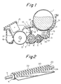
- a developing apparatus according to a first embodiment will be described with reference to Figs. 1 to 3.
- a developing apparatus for supplying a developer to an electrostatic latent image carrier and developing thereof comprises a toner cartridge 1 for containing a toner 1a as the developer, a toner hopper 2 formed under the toner cartridge 1 for storing or stagnating the toner 1a fallen from the toner cartridge 1, a stirring shaft 3 in the toner hopper 2 for stirring the toner 1a stagnant in the toner hopper 2, a supply roller 4 rotatably provided in the lower portion aslant the stirring shaft 3 for delivering and supplying the toner 1a, a toner delivery restriction plate 20 provided between the toner hopper 2 and the supply roller 4 for restricting the amount of supply of the toner.
- the toner cartridge 1 is provided with a shutter 1b provided thereunder and an opening 1c to allow the toner 1a to fall downward therethrough by opening the shutter 1b.
- the stirring shaft 3 is rotated in the direction of the arrow A for stirring the toner stagnant in the toner hopper 2.
- the supply roller 4 is made of foaming materials such as urethane and the like and conductive.
- the supply roller 4 has a central shaft 5 made of a metal to which a predetermined bias current is applied, not shown.
- the toner delivery restriction plate 20 is fixed to a frame 21.
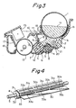
- the toner delivery restriction plate 20 has a length substantially same as that of the axial length of the supply roller 4 as shown in Fig. 2 and is bent in a doglegged shape in cross section.
- a part of the plate 20 covers the supply roller 4 and has a plurality of through holes 22.
- the toner in the toner hopper 2 can reach the supply roller 4 through the plurality of through holes 22.
- the toner delivery restriction plate 20 is made of a metal but may be made of a resin.
- the through holes 22 are spaced substantially in the same intervals in the axial direction of the supply roller 4.
- the through holes 22 on the first row are staggered with those of the second row in the direction crossing the axial direction of the supply roller 4.
- the intervals of the through holes 22 adjacent to each other on the first row are same as those of the through holes 24 adjacent to each other on the second row.
- the shape of the through holes 22 is oval according to the present invention, it is not limited thereto but may be circular or rectangular.
- the number of the through holes 22 are not necessary to be plural but may be one as a slit extending along the supply roller 4.
- the toner delivery restriction plate 20 contacts the supply roller 4 but the toner delivery restriction plate 20 does not always contact the supply roller 4.
- the developing apparatus further comprises a developing roller 6 rotatably fixed to the developing apparatus by driving means, not shown, a developing blade 8 disposed over and contacting the developing roller 6 for thinning a toner layer formed around the developing roller 6, a toner reservoir 18 provided at the space defined at the right side of the developing balde 8 for reserving the toner which can not pass through the interval between the developing blade 8 and the developing roller 6, a sensitive drum 13 as an electrostatic latent image carrier rotatably fixed to driving means, not shown and disposed at left side of the developing roller 6, a first charger 15 substantially over the sensitive drum 13 for charging the surface of the sensitive drum 13 and a cleaning portion 16 disposed at the left side of the sensitive drum 13 provided with a cleaning blade 17 for scraping the toner residual on the surface of the sensitive drum 13 after tansferring the image on the substrate of the printing medium.
- a partition plate 12 contacting the developing roller 6 at the bottom of the developing roller 6 for preventing the toner from scattering outside the developing apparatus.
- the developing roller 6 is formed of a conductive and elastic rubber and the like and has a central metal shaft to which a bias voltage is applied.
- the supply roller 4 and the developing roller 6 respectively serve to deliver the toner to the developing portion by the rotation thereof.
- the developing blade 8 comprises a rubber portion 9 contacting the developing roller 6 and a metal portion 10 fixing the rubber portion 9 thereto. A given pressing force is generated in the developing blade 8 when it is pressed by the spring 11 toward the developing roller 6.
- the developing apparatus having the arrangement set forth above is operated as follows.
- Fig. 3 when the power is ON, the stirring shaft 3, the supply roller 4 and the developing roller 6 are respectively rotated by the driving means, not shown, in the directions of the arrows A, B and C.
- the shutter 1b When the shutter 1b is turned, the toner 1a is dropped from the opening 1c of the toner cartridge 1 and joins residual developer at the toner hopper 2.
- the toner 1a enters into the reservoir 18 and is accumulated on the toner delivery restriction plate 20.
- the amount of the toner entered from the toner hopper 2 is kept at a predetermined amount.
- the amount of the toner supplied from the supply roller 4 is restricted by the toner delivery restriction plate 20.
- the size and the numbers of the through holes 22 as illustrated in Fig. 2 are set to the extent that the amount of the toner passing the through holes 22 is slightly greater than the amount of the toner which is restricted by the developing blade 8.
- the toner 1a passed the toner delivery restriction plate 20 and attached to the supply roller 4 is delivered to the toner reservoir 18.
- the amount of the toner 1a supplied afresh from the hopper 2 to the toner reservoir 18 is substantially same as that passed the toner delivery restriction plate 20.
- the toner 1a attached to the surface of the developing roller 6 in the toner reservoir 18 is delivered to the position where the developing roller 6 contacts the developing blade 8 by the rotation of the developing roller 6 per se.
- the toner laid over the developing roller 6 is thinned to a predetermined thickness, e.g. to several ten microns by the developing blade 8. Inasmuch as the amount of the toner in the toner reservoir 18 is kept substantially constant, the toner reservoir 18 is not filled by the toner, hence it does not affect the thinning operation by the developing blade 8.
- the toner 1a is charged by the developing blade 8.
- the thus thinned charged toner is subjected to the development of the elecrostatic latent image at the portion contacting the sensitive drum 13.
- the toner which is not subjected to the development among those attached to the developing roller 6 and residual on the developing roller 6 is rotated by the rotation of the developing roller 6 in the direction of the arrow C and reaches the portion contacting the supply roller 4.
- the supply roller 4 is the roller like a sponge and has a plurality of minute convex and concave portions at the surface thereof.
- the suppy roller also functions to scrape the toner residual on the developing roller by contacting the developing roller 6 and rotating.
- the amount of the toner is restricted so that the toner layer on the developing roller 6 can be thinned appropriately by the developing blade.
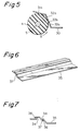
- a developing apparatus according to a second embodiment will be described with reference to Figs. 4 and 5.
- a toner delivery restriction plate 30 is formed to extend so as to cover the supply roller 4 in the entire length thereof.
- the slits 31a in the first row 31 and the slits 32a in the second row function respectively to supply the toner in the toner hopper 2 to the supply roller 4 as the supply slits
- the slits 33a in the third row 33 function to scrape the toner attached to the supply roller as the scraping slits. This is described more in detail with reference to Fig. 5.
- the surface of the supply roller 4 has a plurality of minute convex and concave portions.
- the toner delivery restriction plate 30 contacts the surface of the supply roller 4.
- the toner passed the slits 31a in the first row 31 and the toner passed the slits 32a of the second row 32 are moved toward the supply roller 4.
- the size and the numbers of the slits 31a of the first row 31 and the slits 32a of the second row 32 are determined in the given values so that the amount of the toner to be supplied to the supply roller 4 is optimum.
- the upper ends 33b of the slits 33a in the third row is brought into contact with the supply roller 4 under pressure.
- the supply roller 4, as set forth above, functions to scrape the toner residual on the developing roller 6 but the same roller 4 is likely to be clogged at the surface thereof due to the repetitive delivering operation of the toner. When the surface of the supply roller is clogged the function to scrape the toner residual on the developing roller 6 is not fully carried out. Since the upper ends 33b of the slits 33a of the toner delivery restriction plate 30 is brought into contact with the supply roller 4 under pressure and the supply roller 4 is rotated in the direction of the arrow B, i.e.
- the toner clogged on the surface of the supply roller 4 is scraped.
- the toner in the toner hopper is residual on the toner delivery restriction plate 30 and enters into the slits 33a, the density of the toner is relatively low.
- the supply roller 4 thus eliminating the clogging problem by the upper ends 33b receives the toner again from the slits 32a and 31a.
- a large amount of the toner supplied afresh is delivered into the developing roller, hence the toner is less residual on the surface of the supply roller 4. Since the toner residual on the developing roller 6 is scraped by the supply roller 4, the scraping operation is carried out favorably.
- the toner delivery restriction plate according to the second embodiment functions to restrict the amount of the toner and to scrape the toner residual on the developing roller by eliminating the clogging problem on the supply roller. Accordingly, there are such effects according to the second embodiment that the thickness of the toner layer on the developing roller can be restricted appropriately and the toner residual on the developing roller can be eliminated so that no undesired images occur at the developing process.
- the toner delivery restriction plate can be varied as illustrated in Fig. 6.
- the delivery restriction plate 35 comprises three plates connected with each other with providing predetermined gaps 34 therebetween.
- connecting members 36 for connecting the three plates with each other by providing the predetermined gaps 34 at the both sides and at the central portion of the toner delivery restriction plate 35 alone.
- the sizes of the gaps 34 are set to the extent that the optimum amount of the toner can pass the gaps.
- Edge portions 37 of the toner delivery restriction plate 35 as illustrated in Fig. 7 are brought into contact with the supply roller 4 so as to scrape the toner clogged on the surface of the supply roller 4.
Landscapes
- Physics & Mathematics (AREA)
- General Physics & Mathematics (AREA)
- Dry Development In Electrophotography (AREA)
Claims (5)
- Entwicklungsvorrichtung, die mit einem Behälter (2), in dem ein Entwickler gespeichert ist, und einem Träger (13) eines elektrostatischen latenten Bildes versehen ist, dem der Entwickler zugeführt wird, wobei die Entwicklungsvorrichtung weiterhin folgendes aufweist:
eine Zuführwalze (4), die angrenzend an den Behälter angeordnet ist, um den im Behälter gespeicherten Entwickler zuzuführen, wobei der Entwickler vom Behälter zur Zuführwalze auf einem bestimmten Weg transportiert wird;
eine Entwicklungswalze (6), die angrenzend an den Behälter angeordnet ist und die Zuführwalze kontaktiert, um den von der Zuführwalze zugeführten Entwickler dem Träger des elektrostatischen latenten Bildes zuzuführen;
ein Entwicklungsblatt (8), das mit der Entwicklungswalze unter Anwendung von Druck in Kontakt gebracht wird, um die auf der Entwicklungswalze verteilte Entwicklerschicht dünner zu machen; und
ein Begrenzungsglied (20, 30, 35), das auf dem Weg dazu vorgesehen ist, die Entwicklermenge, die zur Zuführwalze transportiert werden soll, zu begrenzen, wobei das Begrenzungsglied in Kontakt mit der Zuführwalze ist;
dadurch gekennzeichnet, daß
das Begrenzungsglied (20, 30, 35) mit mehreren Reihen von Durchgangslöchern (22) oder Schlitzen (31a, 32a, 33a) oder Lücken (34) versehen ist, die sich in axialer Richtung über die gesamte Länge der Zuführwalze erstrecken, und dadurch, daß
sich der Rand (die Ränder) (33b, 37) der Durchgangslöcher oder Schlitze (33a) oder Lücken (34) einer der mehreren Reihen, die bezüglich der Rotationsrichtung der Zuführwalze stromabwärts positioniert ist, in Kontakt mit der Zuführwalze befindet (befinden). - Entwicklungsvorrichtung nach Anspruch 1, bei der der Rand (die Ränder) (33b, 37) gegen die Zuführwalze (4) gedrückt ist (sind).
- Entwicklungsvorrichtung nach Anspruch 1 oder 2, bei der das Begrenzungsglied (20, 30, 35) eine abgewinkelte Konfiguration aufweist.
- Entwicklungsvorrichung nach einem der Ansprüche 1 bis 3, bei der eine Vielzahl von Durchgangslöchern (22) in axialer Richtung der Zuführwalze in gleichen Abständen angeordnet sind.
- Entwicklungsvorrichtung nach einem der Ansprüche 1 bis 3, bei der das Begrenzungsglied (35) eine Mehrzahl von plattenartigen Gliedern aufweist, die in axialer Richtung der Zuführrolle (4) angeordnet und durch Glieder (36), die die Lücken bilden, miteinander verbunden sind.
Applications Claiming Priority (2)
| Application Number | Priority Date | Filing Date | Title |
|---|---|---|---|
| JP1335069A JPH087493B2 (ja) | 1989-12-26 | 1989-12-26 | 現像装置 |
| JP335069/89 | 1989-12-26 |
Publications (3)
| Publication Number | Publication Date |
|---|---|
| EP0435259A2 EP0435259A2 (de) | 1991-07-03 |
| EP0435259A3 EP0435259A3 (en) | 1991-12-18 |
| EP0435259B1 true EP0435259B1 (de) | 1995-03-08 |
Family
ID=18284415
Family Applications (1)
| Application Number | Title | Priority Date | Filing Date |
|---|---|---|---|
| EP90125509A Expired - Lifetime EP0435259B1 (de) | 1989-12-26 | 1990-12-27 | Entwicklungsgerät |
Country Status (4)
| Country | Link |
|---|---|
| US (1) | US5132734A (de) |
| EP (1) | EP0435259B1 (de) |
| JP (1) | JPH087493B2 (de) |
| DE (1) | DE69017630T2 (de) |
Families Citing this family (15)
| Publication number | Priority date | Publication date | Assignee | Title |
|---|---|---|---|---|
| US5264900A (en) * | 1991-06-14 | 1993-11-23 | Oki Electric Industry Co., Ltd. | Developing device including toner hopper and toner cartridge stirring portions |
| JPH05165317A (ja) * | 1991-12-13 | 1993-07-02 | Toshiba Corp | 現像装置 |
| DE4243096C2 (de) * | 1991-12-20 | 1997-07-17 | Fujitsu Ltd | Entwicklungsvorrichtung zur Verwendung eines Zwei-Komponenten-Entwicklers |
| JPH05224521A (ja) * | 1992-02-13 | 1993-09-03 | Nec Corp | 現像装置及び画像形成装置 |
| US5467175A (en) * | 1992-12-30 | 1995-11-14 | Ricoh Company, Ltd. | Developing device for an image forming apparatus |
| JP3044997B2 (ja) * | 1994-02-16 | 2000-05-22 | ブラザー工業株式会社 | 画像形成装置における現像装置 |
| JP3444017B2 (ja) * | 1994-05-18 | 2003-09-08 | 富士ゼロックス株式会社 | 一成分現像剤を用いる現像装置 |
| JPH08211734A (ja) * | 1995-02-03 | 1996-08-20 | Brother Ind Ltd | 現像装置 |
| JPH08220883A (ja) * | 1995-02-14 | 1996-08-30 | Tec Corp | 現像装置 |
| US5761585A (en) * | 1995-12-28 | 1998-06-02 | Brother Kogyo Kabushiki Kaisha | Cap for toner fillable container and toner fillable container using same |
| KR0174689B1 (ko) * | 1996-09-11 | 1999-04-01 | 삼성전자주식회사 | 현상롤러의 고스트 방지장치 |
| JPH1138746A (ja) * | 1997-07-17 | 1999-02-12 | Brother Ind Ltd | 現像装置およびトナー供給体 |
| US6519437B1 (en) * | 2001-08-23 | 2003-02-11 | Toshiba Tec Kabushiki Kaisha | Prevention of excessive toner accumulation in a developing apparatus |
| KR20050006663A (ko) * | 2003-07-09 | 2005-01-17 | 삼성전자주식회사 | 1성분 비자성 접촉현상방식 화상형성장치 |
| JP5378969B2 (ja) * | 2009-12-09 | 2013-12-25 | 株式会社沖データ | 現像装置および画像形成装置 |
Family Cites Families (12)
| Publication number | Priority date | Publication date | Assignee | Title |
|---|---|---|---|---|
| JPS5915269A (ja) * | 1982-07-17 | 1984-01-26 | Ricoh Co Ltd | 乾式現像装置 |
| JPS6147977A (ja) * | 1984-08-16 | 1986-03-08 | Fuji Xerox Co Ltd | 電子写真複写機の磁気ブラシ現像装置 |
| JPS61159675A (ja) * | 1985-01-07 | 1986-07-19 | Ricoh Co Ltd | 現像装置 |
| JPS62153879A (ja) * | 1985-12-27 | 1987-07-08 | Canon Inc | 現像装置 |
| JPH083678B2 (ja) * | 1986-08-11 | 1996-01-17 | 株式会社東芝 | 現像装置 |
| JPS63129366A (ja) * | 1986-11-19 | 1988-06-01 | Matsushita Electric Ind Co Ltd | 現像装置 |
| KR910003727B1 (ko) * | 1986-12-02 | 1991-06-08 | 마쯔시다덴기산교 가부시기가이샤 | 현상장치 |
| JPS63225274A (ja) * | 1987-03-16 | 1988-09-20 | Canon Inc | 現像装置 |
| JPS63231469A (ja) * | 1987-03-20 | 1988-09-27 | Oki Electric Ind Co Ltd | 現像装置 |
| JPH01154182A (ja) * | 1987-12-11 | 1989-06-16 | Minolta Camera Co Ltd | 現像装置 |
| JPH01276171A (ja) * | 1988-04-28 | 1989-11-06 | Toshiba Corp | 現像装置 |
| US4965639A (en) * | 1989-10-25 | 1990-10-23 | Xerox Corporation | Toner supply cartridge for reproduction and printing machines |
-
1989
- 1989-12-26 JP JP1335069A patent/JPH087493B2/ja not_active Expired - Lifetime
-
1990
- 1990-12-26 US US07/634,348 patent/US5132734A/en not_active Expired - Lifetime
- 1990-12-27 EP EP90125509A patent/EP0435259B1/de not_active Expired - Lifetime
- 1990-12-27 DE DE69017630T patent/DE69017630T2/de not_active Expired - Lifetime
Also Published As
| Publication number | Publication date |
|---|---|
| DE69017630T2 (de) | 1995-10-26 |
| EP0435259A3 (en) | 1991-12-18 |
| DE69017630D1 (de) | 1995-04-13 |
| US5132734A (en) | 1992-07-21 |
| EP0435259A2 (de) | 1991-07-03 |
| JPH03196075A (ja) | 1991-08-27 |
| JPH087493B2 (ja) | 1996-01-29 |
Similar Documents
| Publication | Publication Date | Title |
|---|---|---|
| EP0435259B1 (de) | Entwicklungsgerät | |
| US4481903A (en) | Apparatus for developing an electrostatic latent image on a recording medium | |
| EP0435549B1 (de) | Mit Löchern versehener Druckkopf für einen direkten elektrostatischen Drucker | |
| EP0309586B1 (de) | Entwicklungsvorrichtung | |
| US5754926A (en) | Charging device | |
| US5708921A (en) | Developing device in an image forming apparatus for removing particulate material from the developer | |
| EP0389229A2 (de) | Bilderzeugungsgerät | |
| EP0572738B1 (de) | Aufladungsvorrichtung, Bilderzeugungsgerät und von dem Bilderzeugungsgerät abnehmbare Arbeitseinheit | |
| EP0938033A1 (de) | Entwicklungsvorrichtung und elektrophotographische vorrichtung | |
| US4439781A (en) | Image recording method and apparatus | |
| US4989021A (en) | Cleaning device for conductive magnetic toner and image recording apparatus using same | |
| US5999791A (en) | Cleaning device for electrophotographic apparatus and electrophotographic apparatus having the same | |
| US6337963B1 (en) | Toner recovery system with electrical potential separation for a wet image-forming apparatus | |
| JP2001100493A (ja) | 画像形成装置及びプロセスカートリッジ | |
| JP3327106B2 (ja) | 画像形成装置 | |
| US5826153A (en) | Image-forming machine | |
| JPH075795A (ja) | クリーニング装置 | |
| US5845186A (en) | Wet image forming apparatus including an intermediate transfer body having projections | |
| JP3347243B2 (ja) | 現像装置 | |
| JPH0635242Y2 (ja) | 現像装置 | |
| JP2811332B2 (ja) | 帯電器 | |
| JPH0462387B2 (de) | ||
| JPH0452752Y2 (de) | ||
| JPS6345114B2 (de) | ||
| KR19980018906A (ko) | 화상형성기 및 거기에 적용되는 프로세스 유닛(image-forming machine and process unit adapted thereto) |
Legal Events
| Date | Code | Title | Description |
|---|---|---|---|
| PUAI | Public reference made under article 153(3) epc to a published international application that has entered the european phase |
Free format text: ORIGINAL CODE: 0009012 |
|
| AK | Designated contracting states |
Kind code of ref document: A2 Designated state(s): DE FR GB |
|
| PUAL | Search report despatched |
Free format text: ORIGINAL CODE: 0009013 |
|
| AK | Designated contracting states |
Kind code of ref document: A3 Designated state(s): DE FR GB |
|
| 17P | Request for examination filed |
Effective date: 19920430 |
|
| 17Q | First examination report despatched |
Effective date: 19930323 |
|
| GRAA | (expected) grant |
Free format text: ORIGINAL CODE: 0009210 |
|
| AK | Designated contracting states |
Kind code of ref document: B1 Designated state(s): DE FR GB |
|
| REF | Corresponds to: |
Ref document number: 69017630 Country of ref document: DE Date of ref document: 19950413 |
|
| ET | Fr: translation filed | ||
| PLBE | No opposition filed within time limit |
Free format text: ORIGINAL CODE: 0009261 |
|
| STAA | Information on the status of an ep patent application or granted ep patent |
Free format text: STATUS: NO OPPOSITION FILED WITHIN TIME LIMIT |
|
| 26N | No opposition filed | ||
| REG | Reference to a national code |
Ref country code: GB Ref legal event code: IF02 |
|
| PGFP | Annual fee paid to national office [announced via postgrant information from national office to epo] |
Ref country code: GB Payment date: 20091223 Year of fee payment: 20 Ref country code: FR Payment date: 20091221 Year of fee payment: 20 |
|
| PGFP | Annual fee paid to national office [announced via postgrant information from national office to epo] |
Ref country code: DE Payment date: 20091224 Year of fee payment: 20 |
|
| REG | Reference to a national code |
Ref country code: GB Ref legal event code: PE20 Expiry date: 20101226 |
|
| PG25 | Lapsed in a contracting state [announced via postgrant information from national office to epo] |
Ref country code: GB Free format text: LAPSE BECAUSE OF EXPIRATION OF PROTECTION Effective date: 20101226 |
|
| PG25 | Lapsed in a contracting state [announced via postgrant information from national office to epo] |
Ref country code: DE Free format text: LAPSE BECAUSE OF EXPIRATION OF PROTECTION Effective date: 20101227 |