EP0435040B1 - Plaque de fixation pour une charnière - Google Patents
Plaque de fixation pour une charnière Download PDFInfo
- Publication number
- EP0435040B1 EP0435040B1 EP90123582A EP90123582A EP0435040B1 EP 0435040 B1 EP0435040 B1 EP 0435040B1 EP 90123582 A EP90123582 A EP 90123582A EP 90123582 A EP90123582 A EP 90123582A EP 0435040 B1 EP0435040 B1 EP 0435040B1
- Authority
- EP
- European Patent Office
- Prior art keywords
- plate
- intermediate plate
- base plate
- hinge
- curved
- Prior art date
- Legal status (The legal status is an assumption and is not a legal conclusion. Google has not performed a legal analysis and makes no representation as to the accuracy of the status listed.)
- Expired - Lifetime
Links
- 230000000295 complement effect Effects 0.000 claims description 3
- 238000010276 construction Methods 0.000 description 1
- 238000006073 displacement reaction Methods 0.000 description 1
- 238000004519 manufacturing process Methods 0.000 description 1
- 230000000149 penetrating effect Effects 0.000 description 1
Images


Classifications
-
- E—FIXED CONSTRUCTIONS
- E05—LOCKS; KEYS; WINDOW OR DOOR FITTINGS; SAFES
- E05D—HINGES OR SUSPENSION DEVICES FOR DOORS, WINDOWS OR WINGS
- E05D7/00—Hinges or pivots of special construction
- E05D7/04—Hinges adjustable relative to the wing or the frame
- E05D7/0407—Hinges adjustable relative to the wing or the frame the hinges having two or more pins and being specially adapted for cabinets or furniture
-
- E—FIXED CONSTRUCTIONS
- E05—LOCKS; KEYS; WINDOW OR DOOR FITTINGS; SAFES
- E05Y—INDEXING SCHEME ASSOCIATED WITH SUBCLASSES E05D AND E05F, RELATING TO CONSTRUCTION ELEMENTS, ELECTRIC CONTROL, POWER SUPPLY, POWER SIGNAL OR TRANSMISSION, USER INTERFACES, MOUNTING OR COUPLING, DETAILS, ACCESSORIES, AUXILIARY OPERATIONS NOT OTHERWISE PROVIDED FOR, APPLICATION THEREOF
- E05Y2900/00—Application of doors, windows, wings or fittings thereof
- E05Y2900/20—Application of doors, windows, wings or fittings thereof for furniture, e.g. cabinets
-
- Y—GENERAL TAGGING OF NEW TECHNOLOGICAL DEVELOPMENTS; GENERAL TAGGING OF CROSS-SECTIONAL TECHNOLOGIES SPANNING OVER SEVERAL SECTIONS OF THE IPC; TECHNICAL SUBJECTS COVERED BY FORMER USPC CROSS-REFERENCE ART COLLECTIONS [XRACs] AND DIGESTS
- Y10—TECHNICAL SUBJECTS COVERED BY FORMER USPC
- Y10S—TECHNICAL SUBJECTS COVERED BY FORMER USPC CROSS-REFERENCE ART COLLECTIONS [XRACs] AND DIGESTS
- Y10S16/00—Miscellaneous hardware, e.g. bushing, carpet fastener, caster, door closer, panel hanger, attachable or adjunct handle, hinge, window sash balance
- Y10S16/43—Hinge mounting bracket
Definitions
- the invention relates to a mounting plate for a hinge, preferably a furniture hinge, consisting of a base plate and an intermediate plate that is adjustable relative to this, which can be connected to the base plate in different setting positions and on which a conventional hinge arm is fastened.
- furniture hinges can be adjusted after assembly in such a way that the hinges are adjustable in the depth of the furniture, in the lateral direction and, if possible, also in the direction of the height of the furniture.
- Furniture hinges are usually connected by a pot-like hinge part to the back of a door wing, which is coupled via a hinge mechanism to a hinge arm that is adjustable for adjustment in modern hinges in two or three coordinate directions and is held on a mounting or fastening plate on the inner surface of one Carrying wall of a piece of furniture is attached.
- a multi-part mounting plate which enables adjustment of a hinge arm in 3 coordinate directions, is known for example from DE-A-38 41 405.
- a wedge-shaped fitting part which consists of two elbows, the straight legs of which are pivotally connected to one another and whose angled legs are curved concentrically to the pivot axis, overlap one another and can be clamped together by a screw in different angular positions , and through which the mounting plate of a furniture hinge can be attached to the supporting wall of a piece of furniture in an angular position corresponding to the wedge angle, so that the hinged furniture door in its closed position assumes a greater angle than 90 degrees to the supporting wall.
- the assembly and adjustment of such wedge-shaped intermediate pieces is relatively complex and complicated.
- a special hinge arm is known from AT-381 556 B, which is pivotally connected in its front area to an articulated support which is closed at different angular positions the hinge arm can be defined by complementary cylindrical curved surfaces.
- a curved hinge arm is known, which can be set for setting different angular positions of a door deviating from 90 degrees to the supporting wall on a projecting bracket arm attached to the supporting wall with a corresponding curvature.
- the object of the invention is therefore to provide a mounting plate of the type specified above, with the usual type of hinges or the like on the supporting walls of furniture. fasten so that the hinged doors or flaps to the supporting wall assume an angle other than 90 degrees in the closed position.
- the angle of the door to the supporting wall should be continuously adjustable over a large range in a simple manner.
- the intermediate plate of the mounting plate according to the invention is designed in such a way that conventional hinge arms of series-produced hinges can be attached to it.
- the intermediate plate can be designed with regard to their fastening options for the hinge arm like the fastening plate known from DE-PS 34 26 672, so that hinge arms can be screwed to it in an adjustable manner as well as locked.
- the intermediate plate expediently has a concave on its underside and the base plate on its upper side has a correspondingly convex curved support surface.
- the cooperating support surfaces can also be arranged in reverse.
- the radius of curvature of the concavely curved support surface can be smaller than the radius of curvature of the convexly curved support surface, so that the parts of the support surfaces lying on one another can be connected to one another without play.
- the base plate is provided on its underside in the region of the curved support surface with a groove running in the circumferential direction of the support surface and in the base of the groove with an elongated hole of smaller width penetrating the support surface and that a nut is longitudinally displaceable in the groove is guided, which is supported with opposite sides parallel to each other with play on the groove flanks and into which a screw is screwed which penetrates a hole in the curved support surface of the intermediate plate.
- the nut thus forms, as it were, a sliding block guided in the groove and supported on its step-like shoulders, via which the plates can be connected to one another in the set angular positions.
- the intermediate plate can be provided with laterally projecting pins which are guided in lateral guide grooves or on lateral guide edges or guide ribs of the base plate, which are curved concentrically about the same axis of curvature as the support surface. Pins and guides can of course also be replaced.
- the curved support surfaces only extend over part of the lengths of the base and intermediate plates. Since the intermediate plate also performs a translatory movement when it is displaced on the base plate for the angular adjustment, the size of this translational displacement can be reduced if the curved support surfaces are given a correspondingly smaller radius of curvature.
- the shift that takes place according to the angle setting is taken into account, since this basically remains constant for the specified angle.
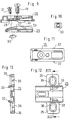
- the base plate has an elongated central part 4 which is essentially rectangular in plan view and which, according to line 5 in FIG. 3, has a convex cylindrical shell-shaped curvature.
- the intermediate plate 3 is provided on its underside with a complementarily convex support surface 6. Between the convex cylindrical shell-shaped support surfaces 6 of the intermediate plate 3, a recess is provided, into which the ramp-like and also curved elevation 7 projects, which is provided in the central region of the support surface 4 of the base plate in the manner shown in FIGS. 3 and 6.
- the ramp-like elevation 7 is provided with a rectangular elongated hole 9 in the manner shown in FIG.
- the slot 9 is provided in the bottom of a downwardly open curved groove of the cover plate 2, in which the sliding nut 10 is guided.
- the sliding nut 10 is square in plan view and has step-shaped shoulders 11 on opposite sides. With these paragraphs 11, the sliding nut 10 is supported on the edges of the elongated hole 9, while the retracted sides of the sliding nut 10 are held non-rotatably between the side edges of the elongated hole 9.
- the intermediate plate 3 is provided in a recess 12 with a bore 13 for a clamping screw 14 which is screwed into the sliding nut 10 in the manner shown in FIGS. 1 and 2.
- the intermediate plate 3 is provided in its front area with opposite pin-like projections 15, which are guided in lateral grooves 16 of the base plate 2.
- the intermediate plate 3 is provided with a central base-like elevation 17, which in its central region has a threaded bore 18 for screwing in a fastening screw 19 for fastening a hinge arm or another one Hinge arm supporting intermediate plate is provided.
- the upper side of the intermediate plate 3 is designed in such a way that hinge arms, which are standard and which are produced in series, can be attached to it.
- a further intermediate plate 21 carrying the hinge arm 20 is screwed onto the fastening plate 1 by the fastening screw 19.
- the hinge arm 20 and this further intermediate plate 21 are designed in the manner described in DE-OS 38 41 405 with reference to FIG.
- the further intermediate plate 21 can be locked by a snap connection with the intermediate plate carrying it.
- the intermediate plate 21 is screwed to the intermediate plate 3 in the manner described in DE-OS 38 41 405 as an alternative fastening option.
- the base plate 25 and the intermediate plate 26 are provided with support surfaces 27, 28 curved only in the shape of a cylindrical shell over part of their length. Since the support surfaces 27, 28 have a smaller radius of curvature, the intermediate plate 26 performs only a smaller translatory movement in the longitudinal direction when it is pivoted on the base plate 25.
- the base plate 25 and the intermediate plate 26 can also be clamped together in the set angular positions in the second embodiment in the manner corresponding to FIGS. 1 to 6 by means of a sliding nut 30 and a clamping screw 31.
- the intermediate plate 26 is in turn provided with lateral pin-like projections 32 which engage behind arcuate, strip-like projections 33 in side parts of the base plate 25.
- the base plates 2 and 25 are provided with side wing-like extensions 35 which have elongated holes 36 which serve for the height-adjustable fastening of the base plates to supporting walls by means of corresponding fastening screws.
- a further intermediate plate 21 is fastened on the intermediate plate 26 in a manner corresponding to FIGS. 1 and 2 by means of a fastening screw 19 which is pivotally connected to the hinge arm 20 in an adjustable manner.
Landscapes
- Engineering & Computer Science (AREA)
- Mechanical Engineering (AREA)
- Hinges (AREA)
Claims (6)
- Plaque de fixation pour une charnière, de préférence une charnière de meuble, consistant en une plaque de fond (2, 25) et une plaque intermédiaire (3, 26) réglable par rapport à la première, qui peut être raccordée à la plaque de fond (2, 25) en diverses positions de réglage et sur laquelle un bras de charnière ordinaire (20) est fixé,
caractérisée en ce que
la face supérieure de la plaque de fond (2, 25) qui est opposée à son côté servant à la fixation à un mur portant, et la face inférieure de la plaque intermédiaire (3, 26) qui est opposée à sa face servant à la fixation avec le bras de charnière (20), consistent du moins partiellement en surfaces complémentaires à courbure cylindrique (5, 6 ; 27, 28),
que la plaque de fond (2, 25) et la plaque intermédiaire (3, 26) s'appuient réciproquement par l'intermédiaire des surfaces complémentaires à courbure cylindrique (5, 6 ; 27, 28), et que les axes de courbure des surfaces à courbure cylindrique s'étendent transversalement par rapport au plan central longitudinal de la plaque de fond et de la plaque intermédiaire. - Plaque de fixation selon la revendication 1, caractérisée en ce que la plaque intermédiaire (3, 26) présente sur sa face inférieure une surface d'appui à courbure concave, et la plaque de fond (2, 25) sur sa face supérieure une surface d'appui à courbure convexe correspondante.
- Plaque de fixation selon les revendications 1 ou 2, caractérisée en ce que le rayon de courbure de la surface à courbure concave (6, 28) est inférieur au rayon de courbure de la surface d'appui à courbure convexe (5, 27).
- Plaque de fixation selon l'une quelconque des revendications 1 à 3, caractérisée en ce que la plaque de fond (2, 25) sur sa face inférieure dans la zone de la surface d'appui courbée présente une rainure s'étendant en direction de la circonférence de la surface d'appui et le fond de la rainure un trou oblong (9) de largeur plus faible traversant la surface d'appui, et qu'un écrou (10, 30) est guidé dans la rainure de manière à pouvoir se déplacer dans le sens longitudinal, qui s'appuie avec un jeu moyennant des côtés opposés et réciproquement parallèles contre les flancs de la rainure ou les bords du trou oblong, et qui est vissé dans la vis (14, 31) qui traverse un perçage dans la surface d'appui courbée de la plaque intermédiaire.
- Plaque de fixation selon l'une quelconque des revendications 1 à 4, caractérisée en ce que la plaque intermédiaire (3, 25) est pourvue d'un tenon latéralement en saillie qui est guidé dans des rainures de guidage latérales ou des arêtes de guidage latérales, ou des nervures de guidage de la plaque de fond, qui sont courbées de manière concentrique autour du même axe de courbure que les surfaces d'appui.
- Plaque de fixation selon l'une quelconque des revendications 1 à 5, caractérisée en ce que les surfaces d'appui courbées (27, 28) s'étendent seulement par dessus une partie de la longueur des plaques de fond et intermédiaire (25, 26).
Applications Claiming Priority (2)
| Application Number | Priority Date | Filing Date | Title |
|---|---|---|---|
| DE3943330 | 1989-12-29 | ||
| DE3943330A DE3943330C1 (fr) | 1989-12-29 | 1989-12-29 |
Publications (2)
| Publication Number | Publication Date |
|---|---|
| EP0435040A1 EP0435040A1 (fr) | 1991-07-03 |
| EP0435040B1 true EP0435040B1 (fr) | 1994-10-05 |
Family
ID=6396619
Family Applications (1)
| Application Number | Title | Priority Date | Filing Date |
|---|---|---|---|
| EP90123582A Expired - Lifetime EP0435040B1 (fr) | 1989-12-29 | 1990-12-07 | Plaque de fixation pour une charnière |
Country Status (6)
| Country | Link |
|---|---|
| US (1) | US5099547A (fr) |
| EP (1) | EP0435040B1 (fr) |
| JP (1) | JPH0686778B2 (fr) |
| AT (1) | ATE112605T1 (fr) |
| DE (2) | DE3943330C1 (fr) |
| ES (1) | ES2063232T3 (fr) |
Families Citing this family (9)
| Publication number | Priority date | Publication date | Assignee | Title |
|---|---|---|---|---|
| DE4134828C2 (de) * | 1991-10-22 | 2001-11-15 | Lautenschlaeger Mepla Werke | Montageplatte für Möbelscharniere |
| DE4236444C2 (de) * | 1992-10-28 | 1994-08-04 | Salice Arturo Spa | Scharnier, vorzugsweise Möbelscharnier |
| AT405553B (de) * | 1994-09-06 | 1999-09-27 | Blum Gmbh Julius | Rahmenscharnier |
| AT409398B (de) * | 1998-09-04 | 2002-07-25 | Blum Gmbh Julius | Möbelscharnier |
| IT246611Y1 (it) * | 1999-03-26 | 2002-04-09 | Franco Ferrari | Base per cerniere con inclinazione regolabile |
| SI1875024T1 (sl) * | 2005-04-29 | 2015-05-29 | Praemeta Gmbh & Co. Kg | Ĺ arnir |
| US7594300B2 (en) * | 2006-06-20 | 2009-09-29 | Hardware Resources, Inc. | Adjustable hinge |
| US8839488B2 (en) * | 2006-06-20 | 2014-09-23 | Hardware Resources, Inc. | Adjustable hinge |
| DE102015226543A1 (de) | 2015-12-22 | 2017-06-22 | Rolls-Royce Deutschland Ltd & Co Kg | Triebwerksverkleidung |
Family Cites Families (8)
| Publication number | Priority date | Publication date | Assignee | Title |
|---|---|---|---|---|
| JPS5559061U (fr) * | 1978-10-18 | 1980-04-22 | ||
| DE3006428A1 (de) * | 1980-02-21 | 1981-08-27 | Richard Heinze Gmbh & Co Kg, 4900 Herford | Grund- oder verstellplatte fuer moebelscharniere |
| DE3217104A1 (de) * | 1982-05-07 | 1983-11-10 | Karl Lautenschläger KG, Möbelbeschlagfabrik, 6107 Reinheim | Moebelscharnier |
| DE8313305U1 (de) * | 1983-05-05 | 1983-09-15 | Richard Heinze Gmbh & Co Kg, 4900 Herford | Tuer- oder klappenscharnier |
| AT381556B (de) * | 1983-12-02 | 1986-11-10 | Blum Gmbh Julius | Scharnier |
| DE3426672A1 (de) * | 1984-07-19 | 1986-01-30 | Arturo Salice S.P.A., Novedrate, Como | Scharnierarm fuer ein moebelscharnier o. dgl. |
| DE3511493A1 (de) * | 1985-03-29 | 1986-10-09 | Karl Lautenschläger KG, Möbelbeschlagfabrik, 6107 Reinheim | Moebelscharnier |
| DE3841405A1 (de) * | 1988-06-29 | 1990-01-04 | Salice Arturo Spa | Scharnierarm mit einer befestigungsplatte zu dessen befestigung an einem moebelteil o. dgl. |
-
1989
- 1989-12-29 DE DE3943330A patent/DE3943330C1/de not_active Expired - Fee Related
-
1990
- 1990-12-07 ES ES90123582T patent/ES2063232T3/es not_active Expired - Lifetime
- 1990-12-07 DE DE59007390T patent/DE59007390D1/de not_active Expired - Fee Related
- 1990-12-07 AT AT90123582T patent/ATE112605T1/de not_active IP Right Cessation
- 1990-12-07 EP EP90123582A patent/EP0435040B1/fr not_active Expired - Lifetime
- 1990-12-26 US US07/632,385 patent/US5099547A/en not_active Expired - Lifetime
- 1990-12-28 JP JP2409007A patent/JPH0686778B2/ja not_active Expired - Fee Related
Also Published As
| Publication number | Publication date |
|---|---|
| ES2063232T3 (es) | 1995-01-01 |
| ATE112605T1 (de) | 1994-10-15 |
| JPH04128486A (ja) | 1992-04-28 |
| EP0435040A1 (fr) | 1991-07-03 |
| US5099547A (en) | 1992-03-31 |
| DE3943330C1 (fr) | 1991-07-11 |
| DE59007390D1 (de) | 1994-11-10 |
| JPH0686778B2 (ja) | 1994-11-02 |
Similar Documents
| Publication | Publication Date | Title |
|---|---|---|
| DE3502175C2 (fr) | ||
| EP0476325B1 (fr) | Ecran pour douche | |
| DE19615077C2 (de) | Ständer für eine Computer-Tastatur | |
| AT6962U1 (de) | Scharnier | |
| DE3530776C2 (fr) | ||
| EP0437750A1 (fr) | Plaque de fixation pour la fixation d'un bras de charnière | |
| EP0271053A2 (fr) | Charnière pour portes, fenêtres ou similaire | |
| EP0435040B1 (fr) | Plaque de fixation pour une charnière | |
| DE2541554A1 (de) | Verbindungsbeschlag fuer moebel | |
| EP0601324A1 (fr) | Charnière de meuble | |
| EP0386342A1 (fr) | Vantail de porte, en particulier dans une séparation pour douche | |
| EP1091067A1 (fr) | Charnière pour portes ou fenêtres | |
| DE4242597A1 (de) | Beschlag zum Anhängen einer Ganzglas-Schiebetür | |
| DE3511493C2 (fr) | ||
| DE3412953C2 (fr) | ||
| DD295407A5 (de) | Scharnier | |
| DE3920141C1 (fr) | ||
| AT390471B (de) | Moebelscharnier mit einer seiten- und tiefeneinstelleinrichtung | |
| DE19642638C5 (de) | Türband | |
| DE4218430A1 (de) | Einstellbares Gelenkband für Fenster oder Türen | |
| DE2149503C3 (de) | Möbelscharnier | |
| DE2823090C2 (de) | In den Endlagen arretierendes Viergelenkscharnier insbesondere für um eine horizontale Achse verschwenkbare Klappen an Möbeln | |
| DE3316048A1 (de) | Moebelscharnier | |
| EP1563152A1 (fr) | Charniere | |
| DD237787A5 (de) | Moebelscharnier |
Legal Events
| Date | Code | Title | Description |
|---|---|---|---|
| PUAI | Public reference made under article 153(3) epc to a published international application that has entered the european phase |
Free format text: ORIGINAL CODE: 0009012 |
|
| AK | Designated contracting states |
Kind code of ref document: A1 Designated state(s): AT DE ES IT |
|
| 17P | Request for examination filed |
Effective date: 19911016 |
|
| 17Q | First examination report despatched |
Effective date: 19911205 |
|
| GRAA | (expected) grant |
Free format text: ORIGINAL CODE: 0009210 |
|
| AK | Designated contracting states |
Kind code of ref document: B1 Designated state(s): AT DE ES IT |
|
| REF | Corresponds to: |
Ref document number: 112605 Country of ref document: AT Date of ref document: 19941015 Kind code of ref document: T |
|
| REF | Corresponds to: |
Ref document number: 59007390 Country of ref document: DE Date of ref document: 19941110 |
|
| ITF | It: translation for a ep patent filed |
Owner name: BREVETTI S.R.L. |
|
| REG | Reference to a national code |
Ref country code: ES Ref legal event code: FG2A Ref document number: 2063232 Country of ref document: ES Kind code of ref document: T3 |
|
| PLBE | No opposition filed within time limit |
Free format text: ORIGINAL CODE: 0009261 |
|
| STAA | Information on the status of an ep patent application or granted ep patent |
Free format text: STATUS: NO OPPOSITION FILED WITHIN TIME LIMIT |
|
| 26N | No opposition filed | ||
| PGFP | Annual fee paid to national office [announced via postgrant information from national office to epo] |
Ref country code: ES Payment date: 20071227 Year of fee payment: 18 |
|
| PGFP | Annual fee paid to national office [announced via postgrant information from national office to epo] |
Ref country code: AT Payment date: 20071219 Year of fee payment: 18 Ref country code: IT Payment date: 20071220 Year of fee payment: 18 |
|
| PGFP | Annual fee paid to national office [announced via postgrant information from national office to epo] |
Ref country code: DE Payment date: 20071221 Year of fee payment: 18 |
|
| PG25 | Lapsed in a contracting state [announced via postgrant information from national office to epo] |
Ref country code: AT Free format text: LAPSE BECAUSE OF NON-PAYMENT OF DUE FEES Effective date: 20081207 |
|
| PG25 | Lapsed in a contracting state [announced via postgrant information from national office to epo] |
Ref country code: DE Free format text: LAPSE BECAUSE OF NON-PAYMENT OF DUE FEES Effective date: 20090701 |
|
| REG | Reference to a national code |
Ref country code: ES Ref legal event code: FD2A Effective date: 20081209 |
|
| PG25 | Lapsed in a contracting state [announced via postgrant information from national office to epo] |
Ref country code: ES Free format text: LAPSE BECAUSE OF NON-PAYMENT OF DUE FEES Effective date: 20081209 |
|
| PG25 | Lapsed in a contracting state [announced via postgrant information from national office to epo] |
Ref country code: IT Free format text: LAPSE BECAUSE OF NON-PAYMENT OF DUE FEES Effective date: 20081207 |