EP0435040B1 - Fitting plate for a hinge - Google Patents
Fitting plate for a hinge Download PDFInfo
- Publication number
- EP0435040B1 EP0435040B1 EP90123582A EP90123582A EP0435040B1 EP 0435040 B1 EP0435040 B1 EP 0435040B1 EP 90123582 A EP90123582 A EP 90123582A EP 90123582 A EP90123582 A EP 90123582A EP 0435040 B1 EP0435040 B1 EP 0435040B1
- Authority
- EP
- European Patent Office
- Prior art keywords
- plate
- intermediate plate
- base plate
- hinge
- curved
- Prior art date
- Legal status (The legal status is an assumption and is not a legal conclusion. Google has not performed a legal analysis and makes no representation as to the accuracy of the status listed.)
- Expired - Lifetime
Links
Images


Classifications
-
- E—FIXED CONSTRUCTIONS
- E05—LOCKS; KEYS; WINDOW OR DOOR FITTINGS; SAFES
- E05D—HINGES OR SUSPENSION DEVICES FOR DOORS, WINDOWS OR WINGS
- E05D7/00—Hinges or pivots of special construction
- E05D7/04—Hinges adjustable relative to the wing or the frame
- E05D7/0407—Hinges adjustable relative to the wing or the frame the hinges having two or more pins and being specially adapted for cabinets or furniture
-
- E—FIXED CONSTRUCTIONS
- E05—LOCKS; KEYS; WINDOW OR DOOR FITTINGS; SAFES
- E05Y—INDEXING SCHEME RELATING TO HINGES OR OTHER SUSPENSION DEVICES FOR DOORS, WINDOWS OR WINGS AND DEVICES FOR MOVING WINGS INTO OPEN OR CLOSED POSITION, CHECKS FOR WINGS AND WING FITTINGS NOT OTHERWISE PROVIDED FOR, CONCERNED WITH THE FUNCTIONING OF THE WING
- E05Y2900/00—Application of doors, windows, wings or fittings thereof
- E05Y2900/20—Application of doors, windows, wings or fittings thereof for furnitures, e.g. cabinets
-
- Y—GENERAL TAGGING OF NEW TECHNOLOGICAL DEVELOPMENTS; GENERAL TAGGING OF CROSS-SECTIONAL TECHNOLOGIES SPANNING OVER SEVERAL SECTIONS OF THE IPC; TECHNICAL SUBJECTS COVERED BY FORMER USPC CROSS-REFERENCE ART COLLECTIONS [XRACs] AND DIGESTS
- Y10—TECHNICAL SUBJECTS COVERED BY FORMER USPC
- Y10S—TECHNICAL SUBJECTS COVERED BY FORMER USPC CROSS-REFERENCE ART COLLECTIONS [XRACs] AND DIGESTS
- Y10S16/00—Miscellaneous hardware, e.g. bushing, carpet fastener, caster, door closer, panel hanger, attachable or adjunct handle, hinge, window sash balance
- Y10S16/43—Hinge mounting bracket
Definitions
- the invention relates to a mounting plate for a hinge, preferably a furniture hinge, consisting of a base plate and an intermediate plate that is adjustable relative to this, which can be connected to the base plate in different setting positions and on which a conventional hinge arm is fastened.
- furniture hinges can be adjusted after assembly in such a way that the hinges are adjustable in the depth of the furniture, in the lateral direction and, if possible, also in the direction of the height of the furniture.
- Furniture hinges are usually connected by a pot-like hinge part to the back of a door wing, which is coupled via a hinge mechanism to a hinge arm that is adjustable for adjustment in modern hinges in two or three coordinate directions and is held on a mounting or fastening plate on the inner surface of one Carrying wall of a piece of furniture is attached.
- a multi-part mounting plate which enables adjustment of a hinge arm in 3 coordinate directions, is known for example from DE-A-38 41 405.
- a wedge-shaped fitting part which consists of two elbows, the straight legs of which are pivotally connected to one another and whose angled legs are curved concentrically to the pivot axis, overlap one another and can be clamped together by a screw in different angular positions , and through which the mounting plate of a furniture hinge can be attached to the supporting wall of a piece of furniture in an angular position corresponding to the wedge angle, so that the hinged furniture door in its closed position assumes a greater angle than 90 degrees to the supporting wall.
- the assembly and adjustment of such wedge-shaped intermediate pieces is relatively complex and complicated.
- a special hinge arm is known from AT-381 556 B, which is pivotally connected in its front area to an articulated support which is closed at different angular positions the hinge arm can be defined by complementary cylindrical curved surfaces.
- a curved hinge arm is known, which can be set for setting different angular positions of a door deviating from 90 degrees to the supporting wall on a projecting bracket arm attached to the supporting wall with a corresponding curvature.
- the object of the invention is therefore to provide a mounting plate of the type specified above, with the usual type of hinges or the like on the supporting walls of furniture. fasten so that the hinged doors or flaps to the supporting wall assume an angle other than 90 degrees in the closed position.
- the angle of the door to the supporting wall should be continuously adjustable over a large range in a simple manner.
- the intermediate plate of the mounting plate according to the invention is designed in such a way that conventional hinge arms of series-produced hinges can be attached to it.
- the intermediate plate can be designed with regard to their fastening options for the hinge arm like the fastening plate known from DE-PS 34 26 672, so that hinge arms can be screwed to it in an adjustable manner as well as locked.
- the intermediate plate expediently has a concave on its underside and the base plate on its upper side has a correspondingly convex curved support surface.
- the cooperating support surfaces can also be arranged in reverse.
- the radius of curvature of the concavely curved support surface can be smaller than the radius of curvature of the convexly curved support surface, so that the parts of the support surfaces lying on one another can be connected to one another without play.
- the base plate is provided on its underside in the region of the curved support surface with a groove running in the circumferential direction of the support surface and in the base of the groove with an elongated hole of smaller width penetrating the support surface and that a nut is longitudinally displaceable in the groove is guided, which is supported with opposite sides parallel to each other with play on the groove flanks and into which a screw is screwed which penetrates a hole in the curved support surface of the intermediate plate.
- the nut thus forms, as it were, a sliding block guided in the groove and supported on its step-like shoulders, via which the plates can be connected to one another in the set angular positions.
- the intermediate plate can be provided with laterally projecting pins which are guided in lateral guide grooves or on lateral guide edges or guide ribs of the base plate, which are curved concentrically about the same axis of curvature as the support surface. Pins and guides can of course also be replaced.
- the curved support surfaces only extend over part of the lengths of the base and intermediate plates. Since the intermediate plate also performs a translatory movement when it is displaced on the base plate for the angular adjustment, the size of this translational displacement can be reduced if the curved support surfaces are given a correspondingly smaller radius of curvature.
- the shift that takes place according to the angle setting is taken into account, since this basically remains constant for the specified angle.
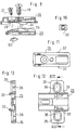
- the base plate has an elongated central part 4 which is essentially rectangular in plan view and which, according to line 5 in FIG. 3, has a convex cylindrical shell-shaped curvature.
- the intermediate plate 3 is provided on its underside with a complementarily convex support surface 6. Between the convex cylindrical shell-shaped support surfaces 6 of the intermediate plate 3, a recess is provided, into which the ramp-like and also curved elevation 7 projects, which is provided in the central region of the support surface 4 of the base plate in the manner shown in FIGS. 3 and 6.
- the ramp-like elevation 7 is provided with a rectangular elongated hole 9 in the manner shown in FIG.
- the slot 9 is provided in the bottom of a downwardly open curved groove of the cover plate 2, in which the sliding nut 10 is guided.
- the sliding nut 10 is square in plan view and has step-shaped shoulders 11 on opposite sides. With these paragraphs 11, the sliding nut 10 is supported on the edges of the elongated hole 9, while the retracted sides of the sliding nut 10 are held non-rotatably between the side edges of the elongated hole 9.
- the intermediate plate 3 is provided in a recess 12 with a bore 13 for a clamping screw 14 which is screwed into the sliding nut 10 in the manner shown in FIGS. 1 and 2.
- the intermediate plate 3 is provided in its front area with opposite pin-like projections 15, which are guided in lateral grooves 16 of the base plate 2.
- the intermediate plate 3 is provided with a central base-like elevation 17, which in its central region has a threaded bore 18 for screwing in a fastening screw 19 for fastening a hinge arm or another one Hinge arm supporting intermediate plate is provided.
- the upper side of the intermediate plate 3 is designed in such a way that hinge arms, which are standard and which are produced in series, can be attached to it.
- a further intermediate plate 21 carrying the hinge arm 20 is screwed onto the fastening plate 1 by the fastening screw 19.
- the hinge arm 20 and this further intermediate plate 21 are designed in the manner described in DE-OS 38 41 405 with reference to FIG.
- the further intermediate plate 21 can be locked by a snap connection with the intermediate plate carrying it.
- the intermediate plate 21 is screwed to the intermediate plate 3 in the manner described in DE-OS 38 41 405 as an alternative fastening option.
- the base plate 25 and the intermediate plate 26 are provided with support surfaces 27, 28 curved only in the shape of a cylindrical shell over part of their length. Since the support surfaces 27, 28 have a smaller radius of curvature, the intermediate plate 26 performs only a smaller translatory movement in the longitudinal direction when it is pivoted on the base plate 25.
- the base plate 25 and the intermediate plate 26 can also be clamped together in the set angular positions in the second embodiment in the manner corresponding to FIGS. 1 to 6 by means of a sliding nut 30 and a clamping screw 31.
- the intermediate plate 26 is in turn provided with lateral pin-like projections 32 which engage behind arcuate, strip-like projections 33 in side parts of the base plate 25.
- the base plates 2 and 25 are provided with side wing-like extensions 35 which have elongated holes 36 which serve for the height-adjustable fastening of the base plates to supporting walls by means of corresponding fastening screws.
- a further intermediate plate 21 is fastened on the intermediate plate 26 in a manner corresponding to FIGS. 1 and 2 by means of a fastening screw 19 which is pivotally connected to the hinge arm 20 in an adjustable manner.
Abstract
Description
Die Erfindung betrifft eine Befestigungsplatte für ein Scharnier, vorzugsweise ein Möbelscharnier, bestehend aus einer Grundplatte und einer relativ zu dieser verstellbaren Zwischenplatte, die mit der Grundplatte in unterschiedlichen Einstellagen verbindbar und auf der ein üblicher Scharnierarm befestigt ist.The invention relates to a mounting plate for a hinge, preferably a furniture hinge, consisting of a base plate and an intermediate plate that is adjustable relative to this, which can be connected to the base plate in different setting positions and on which a conventional hinge arm is fastened.
Aus DE-A-34 26 672 ist eine gattungsgemäße Befestigungsplatte bekannt.From DE-A-34 26 672 a generic mounting plate is known.
Zum Ausgleich unvermeidbarer Herstellungstoleranzen und Montageungenauigkeiten ist es erwünscht, daß sich Möbelscharniere nach ihrer Montage in der Weise justieren lassen, daß die Scharniere in der Tiefe des Möbels, in seitlicher Richtung und möglichst auch in Richtung der Höhe des Möbels verstellbar sind. Möbelscharniere sind üblicherweise durch ein topfartiges Scharnierteil mit der Rückseite eines Türflügels verbunden, das über einen Gelenkmechanismus mit einem Scharnierarm gekoppelt ist, der zur Justierung bei modernen Scharnieren in zwei oder drei Koordinatenrichtungen verstellbar auf einer Montage- oder Befestigungsplatte gehalten ist, die auf der Innenfläche einer Tragwand eines Möbels befestigt ist.To compensate for unavoidable manufacturing tolerances and assembly inaccuracies, it is desirable that furniture hinges can be adjusted after assembly in such a way that the hinges are adjustable in the depth of the furniture, in the lateral direction and, if possible, also in the direction of the height of the furniture. Furniture hinges are usually connected by a pot-like hinge part to the back of a door wing, which is coupled via a hinge mechanism to a hinge arm that is adjustable for adjustment in modern hinges in two or three coordinate directions and is held on a mounting or fastening plate on the inner surface of one Carrying wall of a piece of furniture is attached.
Eine mehrteilige Befestigungsplatte, die eine Einstellung eines Scharnierarms in 3 Koordinatenrichtungen ermöglicht, ist beispielsweise aus der DE-A-38 41 405 bekannt.A multi-part mounting plate, which enables adjustment of a hinge arm in 3 coordinate directions, is known for example from DE-A-38 41 405.
Bei üblichen Möbelscharnieren wird vorausgesetzt, daß sie in ihrer Schließstellung eine Tür oder Klappe in einem Winkel von 90 Grad zu der Tragwand des Möbels halten. Nun gibt es zunehmend auch spezielle Möbel, bei denen in der Schließstellung eine Tür oder Klappe einen von 90 Grad abweichenden Winkel mit der Tragwand einschließt. Da für derartige Fälle übliche serienmäßige Scharniere nicht verwendbar sind, müssen an den jeweiligen Winkel angepaßte Scharniere hergestellt oder aber besondere Beschläge beispielsweise keilförmige Unterlegplatten, verwendet werden.With conventional furniture hinges, it is assumed that they hold a door or flap at an angle of 90 degrees to the supporting wall of the furniture in their closed position. Now there is an increasing number of special pieces of furniture in which, in the closed position, a door or flap encloses an angle with the bulkhead that deviates from 90 degrees. Since standard series hinges cannot be used for such cases, hinges adapted to the respective angle must be produced or special fittings, for example wedge-shaped shims, must be used.
Aus DE-U-83 13 305 ist ein keilförmiges Beschlagteil bekannt, das aus zwei Winkelstücken besteht, deren geraden Schenkel schwenkbar miteinander verbunden und deren gegeneinander gerichteten abgewinkelten Schenkel konzentrisch zur Schwenkachse gekrümmt sind, einander übergreifen und miteinander durch eine Schraube in unterschiedlichen Winkellagen verspannbar sind, und durch das sich die Befestigungssplatte eines Möbelscharniers in einer dem Keilwinkel entsprechenden Winkellage an der Tragwand eines Möbels befestigen läßt, so daß die durch das Scharnier angelenkte Möbeltür in ihrer Schließstellung einen größeren Winkel als 90 Grad zu der Tragwand einnimmt. Die Montage und Einjustierung derartiger keilförmiger Zwischenstücke ist aber verhältnismäßig aufwendig und kompliziert.From DE-U-83 13 305 a wedge-shaped fitting part is known, which consists of two elbows, the straight legs of which are pivotally connected to one another and whose angled legs are curved concentrically to the pivot axis, overlap one another and can be clamped together by a screw in different angular positions , and through which the mounting plate of a furniture hinge can be attached to the supporting wall of a piece of furniture in an angular position corresponding to the wedge angle, so that the hinged furniture door in its closed position assumes a greater angle than 90 degrees to the supporting wall. The assembly and adjustment of such wedge-shaped intermediate pieces is relatively complex and complicated.
Um eine Tür in ihrer Schließstellung in von 90 Grad abweichenden Winkelstellungen an einer Tragwand befestigen zu können, ist aus der AT-381 556 B ein spezieller Scharnierarm bekannt, der in seinem vorderen Bereich schwenkbar mit einem Gelenkträger verbunden ist, der sich in unterschiedlichen Winkellagen zu dem Scharnierarm durch komplementär zylindrisch gekrümmte Flächen festlegen läßt.In order to be able to fasten a door in its closed position to a supporting wall in angular positions deviating from 90 degrees, a special hinge arm is known from AT-381 556 B, which is pivotally connected in its front area to an articulated support which is closed at different angular positions the hinge arm can be defined by complementary cylindrical curved surfaces.
Aus der DE-OS 35 11 493 ist ein gekrümmter Scharnierarm bekannt, der sich zur Einstellung unterschiedlicher von 90 Grad abweichender Winkellagen einer Tür zu der Tragwand an einem an der Tragwand befestigten vorspringenden Halterungsarm mit entsprechender Krümmung festlegen läßt.From DE-OS 35 11 493 a curved hinge arm is known, which can be set for setting different angular positions of a door deviating from 90 degrees to the supporting wall on a projecting bracket arm attached to the supporting wall with a corresponding curvature.
Die beiden zuletzt beschriebenen Scharnierarme bedingen jedoch spezielle Scharnierkonstruktionen, die wegen der üblicherweise nur benötigten kleinen Serien unwirtschaftlich und kostspielig sind und zudem auch einen erhöhten Aufwand bei der separaten Lagerhaltung erfordern.However, the two hinge arms described last require special hinge constructions which are uneconomical and costly because of the small series that are usually only required, and which also require an increased outlay in separate storage.
Aufgabe der Erfindung ist es daher, eine Befestigungsplatte der eingangs angegebenen Art zu schaffen, mit der sich Scharniere üblicher Bauart in der Weise an Tragwänden von Möbeln o.dgl. befestigen lassen, daß die durch diese angelenkten Türen oder Klappen zu der Tragwand einen von 90 Grad abweichenden Winkel in der Schließstellung einnehmen. Dabei soll der Winkel der Tür zu der Tragwand in einfacher Weise stufenlos über einen großen Bereich einstellbar sein.The object of the invention is therefore to provide a mounting plate of the type specified above, with the usual type of hinges or the like on the supporting walls of furniture. fasten so that the hinged doors or flaps to the supporting wall assume an angle other than 90 degrees in the closed position. The angle of the door to the supporting wall should be continuously adjustable over a large range in a simple manner.
Erfindungsgemäß wird diese Aufgabe durch die Merkmale des kennzeichnenden Teils des Patentanspruchs 1 gelöst. Bei der erfindungsgemäßen Befestigungsplatte lassen sich die Grundplatte und die Zwischenplatte in einer gemeinsamen, etwa rechtwinkelig auf diesen stehenden Mittelebene auf unterschiedliche von diesen eingeschlossene Winkel einstellen und sich in frei wählbaren eingestellten Winkellagen miteinander verbinden. Während bei bekannten Befestigungsplatten die Zwischenplatte relativ zur Grundplatte zur Einstellung des Scharniers in der Tiefe oder in Richtung der Höhe oder Seite verstellbar ist, ist die Zwischenplatte bei der erfindungsgemäßen Befestigungsplatte auf der Grundplatte auf gekrümmten Flächen verschieblich geführt, so daß sich die Zwischenplatte zu der Grundplatte zur Einstellung des Winkels der Tür oder Klappe zu der Tragwand in der Schließstellung verschwenken und in gewählten Schwenkstellungen mit dieser verbinden läßt.According to the invention, this object is achieved by the features of the characterizing part of
Die Zwischenplatte der erfindungsgemäßen Befestigungsplatte ist dabei in der Weise ausgestaltet, daß sich übliche Scharnierarme von serienmäßig hergestellten Scharnieren an dieser befestigen lassen. Beispielsweise kann die Zwischenplatte hinsichtlich ihrer Befestigungsmöglichkeiten für den Scharnierarm wie die aus der DE-PS 34 26 672 bekannte Befestigungsplatte ausgebildet sein, so daß sich Scharnierarme mit dieser sowohl in einstellbarer Weise verschrauben als auch verrasten lassen.The intermediate plate of the mounting plate according to the invention is designed in such a way that conventional hinge arms of series-produced hinges can be attached to it. For example, the intermediate plate can be designed with regard to their fastening options for the hinge arm like the fastening plate known from DE-PS 34 26 672, so that hinge arms can be screwed to it in an adjustable manner as well as locked.
Zweckmäßigerweise weist die Zwischenplatte auf ihrer Unterseite eine konkav und die Grundplatte auf ihrer Oberseite eine entsprechend konvex gekrümmte Stützfläche auf. Selbstverständlich können die zusammenwirkenden Stützflächen auch umgekehrt angeordnet sein.The intermediate plate expediently has a concave on its underside and the base plate on its upper side has a correspondingly convex curved support surface. Of course, the cooperating support surfaces can also be arranged in reverse.
Der Krümmungsradius der konkav gekrümmten Stützfläche kann kleiner als der Krümmungsradius der konvex gekrümmten Stützfläche sein, so daß sich die aufeinander liegenden Teile der Stützflächen spiellos miteinander verbinden lassen.The radius of curvature of the concavely curved support surface can be smaller than the radius of curvature of the convexly curved support surface, so that the parts of the support surfaces lying on one another can be connected to one another without play.
In weiterer Ausgestaltung der Erfindung ist vorgesehen, daß die Grundplatte auf ihrer Unterseite im Bereich der gekrümmten Stützfläche mit einer in Umfangsrichtung der Stützfläche verlaufenden Nut und im Grund der Nut mit einem die Stützfläche durchsetzenden Langloch geringerer Breite versehen ist und daß in der Nut eine Mutter längsverschieblich geführt ist, die sich mit gegenüberliegenden zueinander parallelen Seiten mit Spiel an den Nutflanken abstützt und in die eine Schraube eingeschraubt ist, die eine Bohrung in der gekrümmten Stützfläche der Zwischenplatte durchsetzt. Die Mutter bildet somit gleichsam einen in der Nut geführten und auf deren stufenartigen Absätzen abgestützten Gleitstein, über den sich die Platten in den eingestellten Winkellagen miteinander verbinden lassen.In a further embodiment of the invention it is provided that the base plate is provided on its underside in the region of the curved support surface with a groove running in the circumferential direction of the support surface and in the base of the groove with an elongated hole of smaller width penetrating the support surface and that a nut is longitudinally displaceable in the groove is guided, which is supported with opposite sides parallel to each other with play on the groove flanks and into which a screw is screwed which penetrates a hole in the curved support surface of the intermediate plate. The nut thus forms, as it were, a sliding block guided in the groove and supported on its step-like shoulders, via which the plates can be connected to one another in the set angular positions.
Zusätzlich kann die Zwischenplatte mit seitlich auskragenden Zapfen versehen sein, die in seitlichen Führungsnuten oder an seitlichen Führungskanten oder Führungsrippen der Grundplatte, die um die gleiche Krümmungsachse wie die Stützfläche konzentrisch gekrümmt sind, geführt sind. Zapfen und Führungen können selbstverständlich auch ausgetauscht sein.In addition, the intermediate plate can be provided with laterally projecting pins which are guided in lateral guide grooves or on lateral guide edges or guide ribs of the base plate, which are curved concentrically about the same axis of curvature as the support surface. Pins and guides can of course also be replaced.
In weiterer Ausgestaltung der Erfindung ist vorgesehen, daß sich die gekrümmten Stützflächen nur über einen Teil der Längen der Grund- und Zwischenplatten erstrecken. Da die Zwischenplatte bei ihrer Verschiebung auf der Grundplatte zur Winkelverstellung auch eine translatorische Bewegung ausführt, kann die Größe dieser translatorischen Verschiebung verkleinert werden, wenn die gekrümmten Stützflächen einen entsprechend kleineren Krümmungsradius erhalten. Bei der Montage der Grundplatten an den Tragwänden wird die entsprechend der Winkeleinstellung erfolgende Verschiebung berücksichtigt, da diese für den vorgegebenen Winkel grundsätzlich konstant bleibt.In a further embodiment of the invention it is provided that the curved support surfaces only extend over part of the lengths of the base and intermediate plates. Since the intermediate plate also performs a translatory movement when it is displaced on the base plate for the angular adjustment, the size of this translational displacement can be reduced if the curved support surfaces are given a correspondingly smaller radius of curvature. When mounting the base plates on the supporting walls, the shift that takes place according to the angle setting is taken into account, since this basically remains constant for the specified angle.
Ausführungsbeispiele der Erfindung werden nachstehend anhand der Zeichnung näher erläutert. In dieser zeigen
- Fig.1
- einen Längsschnitt durch ein Scharnier mit Befestigungsplatte, die in der Weise eingestellt ist, daß die Tür in der Schließstellung den größtmöglichen Winkel zu der Tragwand einnimmt,
- Fig.2
- einen der Fig.1 entsprechenden Schnitt durch ein Scharnier mit Befestigungsplatte, die auf den kleinsten Winkel der Tür relativ zu der Tragplatte in der Schließstellung eingestellt ist,
- Fig.3
- eine Seitenansicht der aus Grund- und Zwischenplatte betehenden Befestigungsplatte in auseinander gezogener Darstellung ihrer Einzelteile,
- Fig.4
- eine Draufsicht auf die Zwischenplatte,
- Fig.5
- eine Draufsicht und einen Schnitt durch die Gleitmutter,
- Fig.6
- eine Draufsicht auf die Grundplatte,
- Fig.7
- einen der Fig.1 entsprechenden Schnitt durch eine zweite Ausführungsform eines Scharniers mit Befestigungsplatte,
- Fig.8
- einen der Fig.7 entsprechenden Schnitt in der kleinsten Winkeleinstellung,
- Fig.9
- einen Schnitt durch die Befestigungsplatte nach den Fig.7 und 8 im auseinandergezogenen Zustand ihrer Einzelteile,
- Fig.10
- eine Draufsicht auf die Gleitmutter nach den Fig.7 bis 9,
- Fig.11
- eine Draufsicht auf die Zwischenplatte,
- Fig.12
- eine Draufsicht auf die Grundplatte und
- Fig.13
- einen Schnitt durch die Grundplatte längs der Linie XIII-XIII in Fig.12.
- Fig. 1
- 2 shows a longitudinal section through a hinge with a fastening plate, which is set in such a way that the door in the closed position assumes the greatest possible angle to the supporting wall,
- Fig. 2
- 1 shows a section corresponding to FIG. 1 through a hinge with a fastening plate which is set to the smallest angle of the door relative to the support plate in the closed position,
- Fig. 3
- 2 shows a side view of the fastening plate consisting of base plate and intermediate plate in an exploded view of its individual parts,
- Fig. 4
- a plan view of the intermediate plate,
- Fig. 5
- a plan view and a section through the slide nut,
- Fig. 6
- a top view of the base plate,
- Fig. 7
- 2 shows a section corresponding to FIG. 1 through a second embodiment of a hinge with a fastening plate,
- Fig. 8
- a section corresponding to FIG. 7 in the smallest angle setting,
- Fig. 9
- 7 shows a section through the fastening plate according to FIGS. 7 and 8 in the exploded state of its individual parts,
- Fig. 10
- a plan view of the slide nut according to Figures 7 to 9,
- Fig. 11
- a plan view of the intermediate plate,
- Fig. 12
- a top view of the base plate and
- Fig. 13
- a section through the base plate along the line XIII-XIII in Fig.12.
Bei dem Ausführungsbeispiel nach den Fig.1 bis 6 besteht die Befestigungsplatte 1 aus der Grundplatte 2 und der Zwischenplatte 3. Die Grundplatte weist einen in Draufsicht im wesentlichen rechteckigen langgestreckten Mittelteil 4 auf, der gemäß der Linie 5 in Fig.3 einen konvexe zylinderschalenförmige Krümmung aufweist. Die Zwischenplatte 3 ist auf ihrer Unterseite mit einer komplementär konvex gekrümmten Stützfläche 6 versehen. Zwischen den konvex zylinderschalenförmig gekrümmten Stützflächen 6 der Zwischenplatte 3 ist eine Einziehung vorgesehen, in die die rampenartige und ebenfalls gekrümmte Erhöhung 7 ragt, die im mittleren Bereich der Stützfläche 4 der Grundplatte in der aus den Fig.3 und 6 ersichtlichen Weise vorgesehen ist. Die rampenartige Erhöhung 7 ist in der aus Fig.6 ersichtlichen Weise mit einem rechteckigen Langloch 9 versehen. Das Langloch 9 ist in dem Grund einer nach unten hin offenen gekrümmten Nut der Deckplatte 2 vorgesehen, in der die Gleitmutter 10 geführt ist. Die Gleitmutter 10 ist in Draufsicht viereckig ausgebildet und weist an gegenüberliegenden Seiten stufenförmige Absätze 11 auf. Mit diesen Absätzen 11 stützt sich die Gleitmutter 10 auf den Rändern des Langloches 9 ab, während die eingezogenen Seiten der Gleitmutter 10 undrehbar zwischen den Seitenrändern des Langloches 9 gehalten sind. Die Zwischenplatte 3 ist in einer Vertiefung 12 mit einer Bohrung 13 für eine Klemmschraube 14 versehen, die in der aus den Fig.1 und 2 ersichtlichen Weise in die Gleitmutter 10 eingeschraubt ist.In the embodiment according to Figures 1 to 6 there is Fastening
Die Zwischenplatte 3 ist in ihrem vorderen Bereich mit gegenüberliegenden zapfenartigen Vorsprüngen 15 versehen, die in seitliche Nuten 16 der Grundplatte 2 geführt sind.The
Die Zwischenplatte 3 ist mit einer mittleren sockelartigen Erhöhung 17 versehen, die in ihrem mittleren Bereich mit einer Gewindebohrung 18 zum Einschrauben einer Befestigungsschraube 19 zur Befestigung eines Scharnierarmes oder einer weiteren einen Scharnierarm tragenden Zwischenplatte versehen ist.The
Die Oberseite der Zwischenplatte 3 ist so ausgestaltet, daß auf dieser übliche, serienmäßig hergestellte Scharnierarme von Scharnieren befestigt werden können.The upper side of the
Auf die Befestigungsplatte 1 ist nach den Fig.1 und 2 eine weitere den Scharnierarm 20 tragende Zwischenplatte 21 durch die Befestigungsschraube 19 aufgeschraubt. Der Scharnierarm 20 und diese weitere Zwischenplatte 21 sind in der Weise ausgestaltet, wie es in der DE-OS 38 41 405 anhand von deren Fig.2 beschrieben worden ist. Die weitere Zwischenplatte 21 kann durch eine Schnappverbindung mit der diese tragenden Zwischenplatte verrastet werden. Im Beispiel der Fig.1 und 2 ist die Zwischenplatte 21 aber mit der Zwischenplatte 3 in der Weise verschraubt, wie es in der DE-OS 38 41 405 als alternative Befestigungsmöglichkeit beschrieben worden ist.1 and 2, a further
Die Verwendung der in der DE-OS 38 41 405 beschriebenen weiteren Zwischenplatte mit mit dieser schwenkbar verbundenen Scharnierarm ist insofern besonders vorteilhaft, als sich der Scharnierarm 20 durch Betätigung der Stellschraube 22 relativ zu der weiteren Zwischenplatte 21 verschwenken läßt, so daß diese Verschwenkbarkeit zusätzlich zur Justierung der Winkellage des Scharnierarms 20 relativ zu der Tragwand ausgenutzt werden kann.The use of the further intermediate plate described in DE-OS 38 41 405 with this hinge arm pivotally connected to it is particularly advantageous in that the
Bei dem Ausführungsbeispiel nach den Fig.7 bis 13 sind die Grundplatte 25 und die Zwischenplatte 26 nur über einen Teil ihrer Länge mit zylinderschalenförmig gekrümmten Stützflächen 27,28 versehen. Da die Stützflächen 27,28 einen kleineren Krümmungsradius aufweisen, führt die Zwischenplatte 26 bei ihrer Schwenkverstellung auf der Grundplatte 25 nur eine geringere translatorische Bewegung in Längsrichtung aus.In the exemplary embodiment according to FIGS. 7 to 13, the
Die Grundplatte 25 und die Zwischenplatte 26 sind auch bei der zweiten Ausführungsform in der den Fig.1 bis 6 entsprechenden Weise durch eine Gleitmutter 30 und eine Spannschraube 31 in den eingestellten Winkelstellungen miteinander verspannbar.The
Die Zwischenplatte 26 ist wiederum mit seitlichen zapfenartigen Vorsprüngen 32 versehen, die hinter bogenförmig gekrümmte leistenartige Vorsprünge 33 in Seitenteilen der Grundplatte 25 greift.The
Die Grundplatten 2 und 25 sind mit seitlichen angesetzten flügelartigen Fortsätzen 35 versehen, die Langlöcher 36 aufweisen, die der höhenverstellbare Befestigung der Grundplatten an Tragwänden durch entsprechende Befestigungsschrauben dienen.The
Wie aus den Fig.7 und 8 ersichtlich ist, ist auf der Zwischenplatte 26 in einer den Fig.1 und 2 entsprechenden Weise eine weitere Zwischenplatte 21 durch eine Befestigungsschraube 19 befestigt, die in einstellbarer Weise schwenkbar mit dem Scharnierarm 20 verbunden ist.As can be seen from FIGS. 7 and 8, a further
Claims (6)
- Fitting plate for a hinge, preferably a furniture hinge, comprising a base plate (2, 25) and an intermediate plate (3, 26) which can be moved relative to, and connected at different adjustment positions to said base plate (2, 25), and to which is fixed a conventional hinge arm (20),
characterised in that
the upper face of the base plate (2, 25) opposite to the face which serves to secure said base plate (2, 25) to a bearing wall, and the lower face of the intermediate plate (3, 26) opposite the face which serves to secure said intermediate plate (3, 26) to the hinge arm (20), consists at least in part of complementary cylindrically curved areas (5, 6; 27, 28),
that the base plate (2, 25) and the intermediate plate (3, 26) support each other via these complementary cylindrically curved areas (5, 6; 27, 28), and that the axes of curvature of the cylindrically curved areas run transverse to the longitudinal midplane of the base plate and of the intermediate plate. - Fitting plate according to Claim 1, characterised in that the intermediate plate (3, 26) exhibits at its lower face a concave support area, and that the base plate (2, 25) exhibits at its upper face a correspondingly convex curved support area.
- Fitting plate according to Claim 1 or 2, characterized in that the radius of curvature of the concave area (6, 28) is smaller than the radius of curvature of the convex support area (5, 27).
- Fitting plate according to one of Claims 1 to 3, characterised in that the base plate (2, 25) is provided at its lower face in the area of the curved support area with a groove running in the circumferential direction of the support area, and at the base of the groove with an oblong hole (9) of small width passing through the support area, and that in the groove is located a longitudinally displaceable nut (10, 30) which is supported by opposing and parallel faces with some clearance in the groove flanks or the edges of the oblong hole, into which nut (10, 30) is wound a screw (14, 31) which passes through a hole in the curved support area of the intermediate plate.
- Fitting plate according to one of Claims 1 to 4, characterised in that the intermediate plate (3, 25) is provided with laterally protruding pins which are located in lateral guide grooves or at lateral guide edges or by guide ribs of the base plate which are concentrically curved around the same axis of curvature as that of the support areas.
- Fitting plate according to one of Claims 1 to 5, characterised in that the curved support areas (27, 28) only extend over a portion of the length of the base plate and intermediate plate (25, 26).
Applications Claiming Priority (2)
| Application Number | Priority Date | Filing Date | Title |
|---|---|---|---|
| DE3943330 | 1989-12-29 | ||
| DE3943330A DE3943330C1 (en) | 1989-12-29 | 1989-12-29 |
Publications (2)
| Publication Number | Publication Date |
|---|---|
| EP0435040A1 EP0435040A1 (en) | 1991-07-03 |
| EP0435040B1 true EP0435040B1 (en) | 1994-10-05 |
Family
ID=6396619
Family Applications (1)
| Application Number | Title | Priority Date | Filing Date |
|---|---|---|---|
| EP90123582A Expired - Lifetime EP0435040B1 (en) | 1989-12-29 | 1990-12-07 | Fitting plate for a hinge |
Country Status (6)
| Country | Link |
|---|---|
| US (1) | US5099547A (en) |
| EP (1) | EP0435040B1 (en) |
| JP (1) | JPH0686778B2 (en) |
| AT (1) | ATE112605T1 (en) |
| DE (2) | DE3943330C1 (en) |
| ES (1) | ES2063232T3 (en) |
Families Citing this family (9)
| Publication number | Priority date | Publication date | Assignee | Title |
|---|---|---|---|---|
| DE4134828C2 (en) * | 1991-10-22 | 2001-11-15 | Lautenschlaeger Mepla Werke | Mounting plate for furniture hinges |
| DE4236444C2 (en) * | 1992-10-28 | 1994-08-04 | Salice Arturo Spa | Hinge, preferably furniture hinge |
| AT405553B (en) * | 1994-09-06 | 1999-09-27 | Blum Gmbh Julius | FRAME HINGE |
| AT409398B (en) * | 1998-09-04 | 2002-07-25 | Blum Gmbh Julius | Furniture hinge |
| IT246611Y1 (en) * | 1999-03-26 | 2002-04-09 | Franco Ferrari | HINGE BASE WITH ADJUSTABLE INCLINATION |
| US8347459B2 (en) * | 2005-04-29 | 2013-01-08 | Prämeta GmbH & Co. KG | Hinge |
| US8839488B2 (en) * | 2006-06-20 | 2014-09-23 | Hardware Resources, Inc. | Adjustable hinge |
| US7594300B2 (en) * | 2006-06-20 | 2009-09-29 | Hardware Resources, Inc. | Adjustable hinge |
| DE102015226543A1 (en) * | 2015-12-22 | 2017-06-22 | Rolls-Royce Deutschland Ltd & Co Kg | Engine cowling |
Family Cites Families (8)
| Publication number | Priority date | Publication date | Assignee | Title |
|---|---|---|---|---|
| JPS5559061U (en) * | 1978-10-18 | 1980-04-22 | ||
| DE3006428A1 (en) * | 1980-02-21 | 1981-08-27 | Richard Heinze Gmbh & Co Kg, 4900 Herford | Punched sheet metal furniture hinge plate - has pressed guide seam, and recesses open towards edges of shanks |
| DE3217104A1 (en) * | 1982-05-07 | 1983-11-10 | Karl Lautenschläger KG, Möbelbeschlagfabrik, 6107 Reinheim | Furniture hinge |
| DE8313305U1 (en) * | 1983-05-05 | 1983-09-15 | Richard Heinze Gmbh & Co Kg, 4900 Herford | DOOR OR FLAP HINGE |
| AT381556B (en) * | 1983-12-02 | 1986-11-10 | Blum Gmbh Julius | Hinge |
| DE3426672A1 (en) * | 1984-07-19 | 1986-01-30 | Arturo Salice S.P.A., Novedrate, Como | HINGE ARM FOR A FURNITURE HINGE OR THE LIKE |
| DE3511493A1 (en) * | 1985-03-29 | 1986-10-09 | Karl Lautenschläger KG, Möbelbeschlagfabrik, 6107 Reinheim | FURNITURE HINGE |
| DE3841405A1 (en) * | 1988-06-29 | 1990-01-04 | Salice Arturo Spa | HINGED ARM WITH A FASTENING PLATE THAT FASTENS TO A FURNITURE PART OR THE LIKE. |
-
1989
- 1989-12-29 DE DE3943330A patent/DE3943330C1/de not_active Expired - Fee Related
-
1990
- 1990-12-07 DE DE59007390T patent/DE59007390D1/en not_active Expired - Fee Related
- 1990-12-07 ES ES90123582T patent/ES2063232T3/en not_active Expired - Lifetime
- 1990-12-07 EP EP90123582A patent/EP0435040B1/en not_active Expired - Lifetime
- 1990-12-07 AT AT90123582T patent/ATE112605T1/en not_active IP Right Cessation
- 1990-12-26 US US07/632,385 patent/US5099547A/en not_active Expired - Lifetime
- 1990-12-28 JP JP2409007A patent/JPH0686778B2/en not_active Expired - Fee Related
Also Published As
| Publication number | Publication date |
|---|---|
| JPH0686778B2 (en) | 1994-11-02 |
| JPH04128486A (en) | 1992-04-28 |
| DE59007390D1 (en) | 1994-11-10 |
| US5099547A (en) | 1992-03-31 |
| DE3943330C1 (en) | 1991-07-11 |
| EP0435040A1 (en) | 1991-07-03 |
| ATE112605T1 (en) | 1994-10-15 |
| ES2063232T3 (en) | 1995-01-01 |
Similar Documents
| Publication | Publication Date | Title |
|---|---|---|
| DE3502175C2 (en) | ||
| EP0476325B1 (en) | Shower screen | |
| DE19615077C2 (en) | Stand for a computer keyboard | |
| DE3530776C2 (en) | ||
| EP0437750A1 (en) | Fitting plate for fitting a hinge arm | |
| EP0271053A2 (en) | Hinge for doors, windows or the like | |
| EP0435040B1 (en) | Fitting plate for a hinge | |
| DE2541554A1 (en) | CONNECTING FITTINGS FOR FURNITURE | |
| EP0601324A1 (en) | Cabinet hinge | |
| EP0386342A1 (en) | Door wing, especially for a shower partition | |
| EP1091067A1 (en) | Hinge for doors or windows | |
| DE4242597A1 (en) | Fitting for attaching an all-glass sliding door | |
| DE3511493C2 (en) | ||
| DE3412953C2 (en) | ||
| DD295407A5 (en) | HINGE | |
| DE3920141C1 (en) | ||
| AT390471B (en) | FURNITURE HINGE WITH SIDE AND DEPTH ADJUSTMENT | |
| DE19642638C5 (en) | hinge | |
| DE4218430A1 (en) | Adjustable hinge for windows or doors | |
| DE2149503C3 (en) | Furniture hinge | |
| DE2823090C2 (en) | Four-bar hinge that locks in the end positions, especially for flaps on furniture that can be pivoted about a horizontal axis | |
| DE3316048A1 (en) | Furniture hinge | |
| EP1563152A1 (en) | Joint hinge | |
| DD237787A5 (en) | MOEBELSCHARNIER | |
| EP2287427A2 (en) | Hinge |
Legal Events
| Date | Code | Title | Description |
|---|---|---|---|
| PUAI | Public reference made under article 153(3) epc to a published international application that has entered the european phase |
Free format text: ORIGINAL CODE: 0009012 |
|
| AK | Designated contracting states |
Kind code of ref document: A1 Designated state(s): AT DE ES IT |
|
| 17P | Request for examination filed |
Effective date: 19911016 |
|
| 17Q | First examination report despatched |
Effective date: 19911205 |
|
| GRAA | (expected) grant |
Free format text: ORIGINAL CODE: 0009210 |
|
| AK | Designated contracting states |
Kind code of ref document: B1 Designated state(s): AT DE ES IT |
|
| REF | Corresponds to: |
Ref document number: 112605 Country of ref document: AT Date of ref document: 19941015 Kind code of ref document: T |
|
| REF | Corresponds to: |
Ref document number: 59007390 Country of ref document: DE Date of ref document: 19941110 |
|
| ITF | It: translation for a ep patent filed |
Owner name: BREVETTI S.R.L. |
|
| REG | Reference to a national code |
Ref country code: ES Ref legal event code: FG2A Ref document number: 2063232 Country of ref document: ES Kind code of ref document: T3 |
|
| PLBE | No opposition filed within time limit |
Free format text: ORIGINAL CODE: 0009261 |
|
| STAA | Information on the status of an ep patent application or granted ep patent |
Free format text: STATUS: NO OPPOSITION FILED WITHIN TIME LIMIT |
|
| 26N | No opposition filed | ||
| PGFP | Annual fee paid to national office [announced via postgrant information from national office to epo] |
Ref country code: ES Payment date: 20071227 Year of fee payment: 18 |
|
| PGFP | Annual fee paid to national office [announced via postgrant information from national office to epo] |
Ref country code: AT Payment date: 20071219 Year of fee payment: 18 Ref country code: IT Payment date: 20071220 Year of fee payment: 18 |
|
| PGFP | Annual fee paid to national office [announced via postgrant information from national office to epo] |
Ref country code: DE Payment date: 20071221 Year of fee payment: 18 |
|
| PG25 | Lapsed in a contracting state [announced via postgrant information from national office to epo] |
Ref country code: AT Free format text: LAPSE BECAUSE OF NON-PAYMENT OF DUE FEES Effective date: 20081207 |
|
| PG25 | Lapsed in a contracting state [announced via postgrant information from national office to epo] |
Ref country code: DE Free format text: LAPSE BECAUSE OF NON-PAYMENT OF DUE FEES Effective date: 20090701 |
|
| REG | Reference to a national code |
Ref country code: ES Ref legal event code: FD2A Effective date: 20081209 |
|
| PG25 | Lapsed in a contracting state [announced via postgrant information from national office to epo] |
Ref country code: ES Free format text: LAPSE BECAUSE OF NON-PAYMENT OF DUE FEES Effective date: 20081209 |
|
| PG25 | Lapsed in a contracting state [announced via postgrant information from national office to epo] |
Ref country code: IT Free format text: LAPSE BECAUSE OF NON-PAYMENT OF DUE FEES Effective date: 20081207 |